VacuumChambers PC2123S User manual

Manufacturer / distributor:
VacuumChambers.eu
drControl Dawid Roszczenko
Jodłowa 3A/34
16-001 Ignatki-Osiedle
Poland
E-mail: shop@vacuumchambers.eu; Tel.: +48535312207
2
BEFORE USING, PLEASE READ THIS OPERATING MANUAL. Keep the manual for possible future use, as it may
always be necessary to remember the information contained in the manual, and it must be provided with the
device in the event of reselling the machine or changing the user.
WARNING! In order to avoid the risk of injuries and accidents, as well as to increase work efficiency and
prevent premature failure of the device, read all warnings, safety instructions and paragraphs marked with
the symbol:
Do not dispose of that product as unsorted municipal waste.
Used equipment should be sent to an electro-waste collection point.
Nature friendly company.
All photos used in this manual are illustrative photos. The appearance and quantity of the elements supplied to the
customer, as well as their mutual location may vary depending on the ordered vacuum piston pump.
This operating manual is based on current knowledge and experience. The manufacturer reserves the right to change the
content of this manual without informing the consumer.
Contents
................................................................................................................................................................ 3
............................................................................................................................................... 3
A. Outlet pressure regulation. .............................................................................................................................................. 4
.............................................................................................................................................................................. 5
........................................................................................................................................................................ 5
.................................................................................................................................................. 6
............................................................................................................................................................................. 7
A. Cleaning the exhaust air filter. ......................................................................................................................................... 7
B. Cleaning and replacing the muffler filter. ........................................................................................................................ 8
C. Safety valve. ...................................................................................................................................................................... 8
................................................................................................................................................................................... 8

3
Oil-free piston compressors offered by VacuumChambers.eu are characterized by low noise level, low energy consumption
and safety. They are also characterized by a long service life and high reliability. The oil-free technology allows the compressor to
work wherever contamination of the compressed air with oil particles is unacceptable. As a result, these devices can be widely
used in medical equipment, sanitation, food industry and research. These devices will work both in small workshops and for home
use. They can also be used to clean items with compressed air, inflate wheels, power pneumatic tools, aerate water, etc.
The compressor in a set with a pressure chamber is used in the process of casting details from moulding products such as:
silicone, resin (polyurethane, polyester, epoxy), plaster, wax.
The overpressure generated by the compressor eliminates air
bubbles present in the flooding materials. Suitable pressure chambers for such applications are offered by VacuumChambers.eu.
The compressors described in this manual can produce a maximum relative pressure of 115 psi (8 bar). This value can be
reduced according to the technological requirements of the specific process.
The compressor should be operated in the following conditions: ambient temperature from + 5°C to + 40°C, air humidity up
to 80% at 20°C.
The compressor should be stored and transported in the following conditions: ambient temperature from -15°C to + 50°C, air
humidity up to 95% without condensation of water vapour.
Air compressor consist of:
Photo 1:Compressor (A-side view, B-front view).
1. Handle.
2. Air intake with silencer.
3. Piston pump.
4. Pressure tank.
5. Switch.
6. Safety valve.
7. Tank manometer.
8. Pressure regulator.
9. Air exhaust filter with pressure reducer and
reducer manometer.
10. Outlet valve.
11. Legs.
12. Drain valve.
13. Power cord.
The compressor (Photo 1) consists of an oil-free piston pump (3) and a pressure tank (4). The pump has an air intake equipped
with a silencer with a filter (2) and is firmly mounted on the tank. The pump and the tank are connected by a reinforced pressure
hose to a solenoid valve. The tank is equipped with a handle (1), legs (11) and a drain valve (12). A pressure regulator (8) and an
2
10
3
8
12
4
A. B.
13
5 6 7
11
9
2
3
1
4
4
exhaust air filter with a pressure reducer and reducer manometer (9) are mounted on the tank. The compressor switch (5) is
located on the pressure regulator. The power cord (13) is also connected to the pressure regulator. Additionally, the compressor
has a tank manometer (7), a safety valve (6) and an outlet valve (10). Power tools or pneumatic hoses can be connected to the
compressor's outlet valve. Outlet valve can be closed, which allows to maintain the generated pressure in the compressor, and
facilitates the operation of elements connected to the compressor.
During operation, the piston pump draws air from the outside, increases its pressure and forces it into the pressure tank. The
pressure tank collects the compressed air and allows the pressure generated by the pump to be maintained, even after it stops
working. The pressure regulator controls the pressure inside the tank by repeatedly starting and stopping the piston pump. The
pump will run when relative pressure in the tank is 70 Psi (5 bar) or lower. After starting the pump, the air is compressed until the
pressure reaches the value of 8 bar, then the controller switches the pump off by solenoid valve. The pump start and stop values
are factory set and marked on the controller housing. The pressure inside the tank is constantly monitored and when it drops
below 5 bar, the pump will be restarted. As a result, the pressure in the tank is kept constant - in the range between 5 and 8 bar
relative pressure.
The maximum relative pressure inside the compressor may be 0.8 MPa (8 bar) - this value is given on the compressor
nameplate. The compressor is equipped with a safety valve that prevents the pressure inside the compressor from rising above
this value.
Two manometers are provided to monitor and control the pressure in the pressure vessel and on the outlet valve. The tank
manometer, located below the pressure regulator, shows the pressure inside the tank. The reducer manometer, located on the
air filter, shows the pressure value at the tank outlet valve.
A. Outlet pressure regulation.
The relative pressure inside the compressor's tank is kept constant - between 5 and 8 bar. The pressure at the outlet valve
can be lowered by using the blue pressure reducer located on the exhaust air filter (Photo 2).
Photo 2: Air exhaust filter with pressure reducer and reducer manometer.
To reduce the pressure on the outlet valve, first unlock the regulator knob by gently pulling it upwards. Then the pressure can
be regulated by turning the knob. Turning the knob clockwise will increase the pressure at the compressor outlet valve. Turning
the knob in opposite direction will reduce the pressure at the compressor outlet valve. The value of the set pressure is indicated
on the reducer manometer, located on the outlet air filter. The setting of the reducer can be locked by gently pressing on the
reducer knob.
The relative pressure set in the reducer depends on the pressure in the tank at the moment. If the knob is turned in the
direction of increasing the pressure, but the pressure on the reducer manometer does not increase, it means that the value
indicated on the reducer manometer corresponds to the current value of the pressure in the tank, and it is not possible to reach
higher pressure on the outlet valve at the moment. If the knob is turned in the direction of pressure reduction, but the pressure
indication in the reducer manometer does not decrease, it means that it is not possible to reduce the pressure to a lower value at
the moment.
pressure reducer
reducer manometer
reducer knob

5
The piston pump starts when the pressure drops below a starting value of 5 bar relative pressure. Consequently, if for the
intended process it is required to increase the pressure, which is at the moment higher than the starting pressure value (e.g. the
process requires a relative pressure of 7 bar, and the current pressure in the tank is 6 bar relative pressure), it is necessary to
lower the pressure to a value below 5 bar. This will start the pump, and then increase the pressure to a maximum value of 8 bar.
Pressure can be reduced by opening the compressor outlet valve (positioning the valve handle parallel to the valve).
Remember to close the valve (position the handle perpendicular to the valve). Leaving the outlet valve open may impossible to
overpressure build-up and cause the pump overheating.
1) Make sure the switch is in the "OFF" position before connecting the compressor to the power supply.
2) Close the outlet valve (place the valve handle perpendicular to the valve)
3) Connect the compressor's power cord to the mains supply.
4) Start the compressor by setting the switch to the "ON" position.
5) If the relative pressure in the tank is lower than 5 bar, the piston pump will automatically start, and stop when the pressure
in the tank will increase to 8 bar relative pressure.
6) If the relative pressure in the tank is higher than 5 bar, the pump will not start.
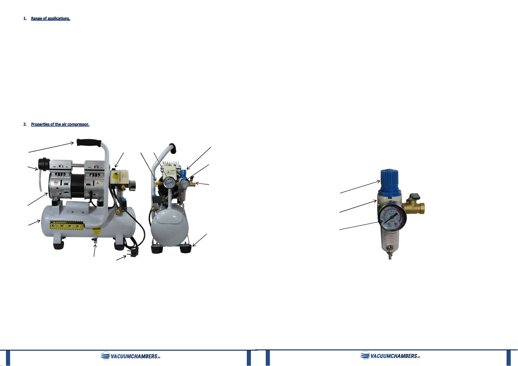
7) The pressure in the tank can be controlled on the tank manometer, which is located below the pressure regulator. When the
compressor is on, and the pump is stopped, the pressure gauge should show a value between 5 and 8 bar relative pressure.
8) Check the pressure at the tank outlet valve. It is indicated on the reducer manometer.
9) If change of pressure on the tank outlet valve is required:
a. Gently lift the blue reducer knob.
b. Set the pressure on the outlet valve by turning the knob clockwise to increase it, or anticlockwise to reduce it. The range
of pressure values that can be achieved on the regulator is limited and is described in section 2. A. „Outlet pressure
regulation.” of this manual.
c. After the intended pressure value has been set, press the reducer knob slightly downwards to lock the settings.
10) Connect with compressor outlet valve the components with which compressor is to cooperate. Follow the operating manual
of those components.
11) Open and close the compressor outlet valve as required by the process.
a. To open the valve and to release the compressed air stream, position the valve handle parallel to the valve.
b. To close the valve and block the compressed air flow, position the outlet valve handle perpendicular to the valve. The
outlet valve can be closed at any time.
12) Before removing any components attached to the outlet valve, always close the outlet valve by positioning the valve handle
perpendicular to the valve.
13) Before connecting new component to the compressor outlet valve, first close the outlet valve by positioning the valve handle
perpendicular to the valve. Disconnect the component connected on the outlet valve and then connect the new component.
Follow the components operating manuals.
14) After finishing work, close the compressor outlet valve by positioning the valve handle perpendicular to the valve.
15) Turn the compressor switch to the "OFF" position.
16) Disconnect the compressor from the power supply.
The compressor should stand on its feet on a level and stable surface, in a dry, clean, dust-free and well-ventilated place. The
distance of the compressor side surfaces from other objects should not be less than 5 cm. The distance of the front and back
of the compressor from other objects should not be less than 10cm. It is necessary to provide free air inlet to the device from
the pump fan side, and to allow free air intake through the air intake with a silencer.
Do not allow the compressor pump to overheat. Exceeding the temperature of 100⁰C on the motor housing significantly
shortens the life of the pump, and in some cases may lead to its complete damage.
If the compressor will not be used for a long period of time, release the compressed air from the tank, cover the compressor,
and then put it in a dry and safe place.
The compressor works without oil. The compressor must not be filled with oil or lubricated, as this may damage the
compressor.
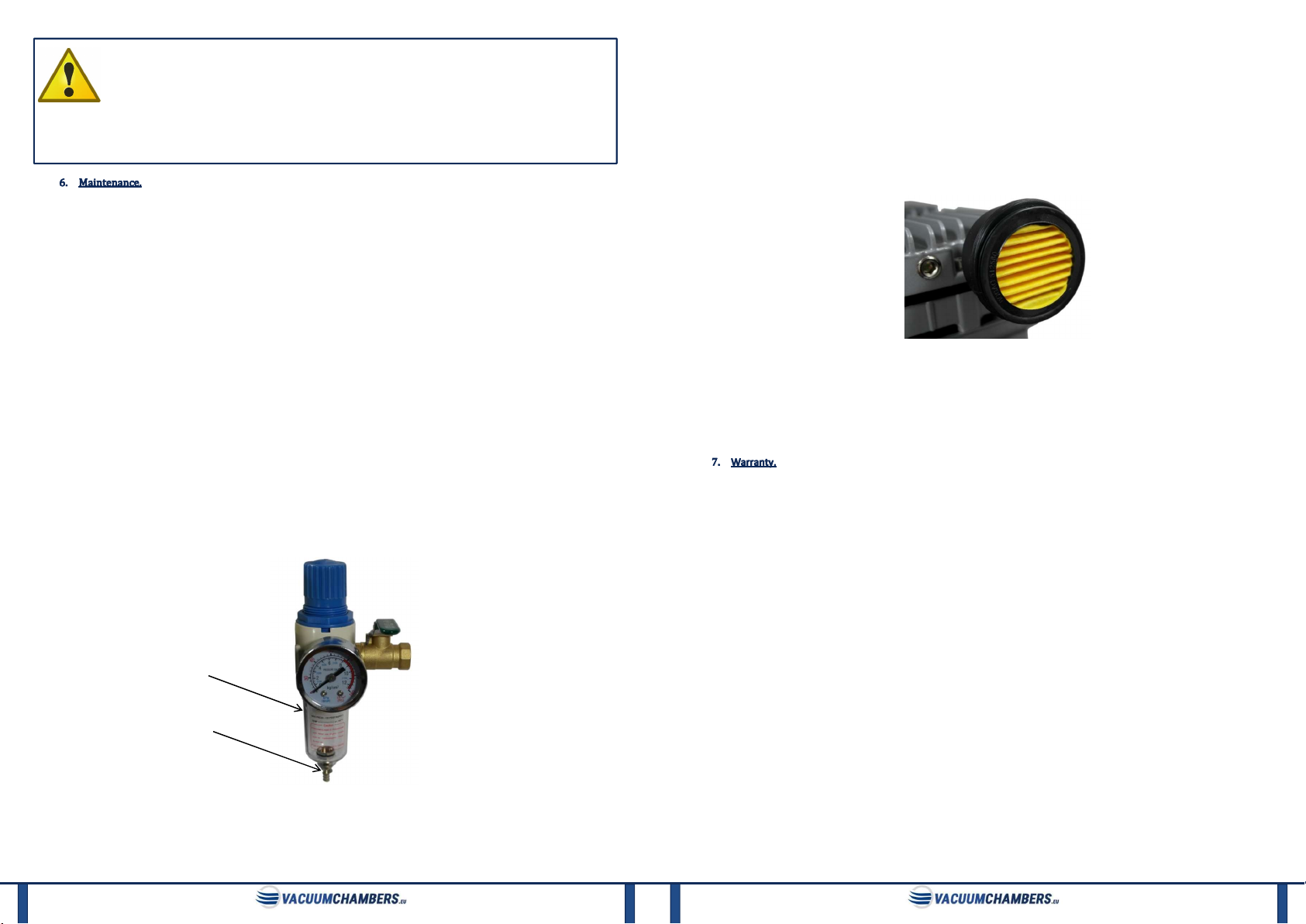
To protect the inside of the tank from corrosion, open the bottom drain valve daily to remove moisture and water that may
have accumulated in the tank due to air compression.
6
If it is not possible to achieve an pressure value as declared by the distributor, this may indicate a leak in the system. Make
sure that all compressor components are tightly connected and work properly. Close the outlet valve (position valve handle
perpendicular to the valve) when checking the compressor for leaks.
If the compressor pump does not start, reduce the pressure in the tank below 4 bar relative pressure.
The compressor is intended to be used only as a source of compressed air. Its use for other purposes is prohibited.
If the safety valve has been activated, check if the rated value in the tank is not exceeded during operation of the device.
The compressor pump is an oil-free piston pump, therefore it is not designed to continuous work. Continuous operation of
the pump may cause it to overheat. In this case, the pump will be automatically turned off. It will be possible for the pump to
resume operation after it has cooled down. This should happen after about 15 minutes of break.
When the power cord is connected to the power supply, the switch is in the "ON" position and the relative pressure in the
tank is less than 5 bar, the pump starts automatically without any warning.
When the pump is turning off, air is blown out of the solenoid valve.
Read the operating instructions before use.
There are warning decals on the compressor pump and the pressure tank, read them before starting work and
follow them.
Before each use of the air compressor, it is necessary to check its technical condition, in particular the supply
cable.
In the event of unusual sounds, exclude compressor from use - possible damage to internal components. Perform servicing
and maintenance of the air compressor periodically.
Carry out all maintenance work when the compressor pump is not hot and air compressor is not running, and is
disconnected from the power supply.
The general rules for the use of equipment working under voltage must be observed.
Before starting work, make sure that the parameters of the power source correspond to the air compressor requirements
specified on the compressor pump.
Make sure that the air compressor complies with the technological requirements, processes and purposes for which it is
to be used. Make sure that the air compressor is not exposed to chemicals that could damage it. The customer is solely
responsible for selecting the appropriate air compressor for the working conditions.
Make sure that the components, with which the compressor will cooperate are suitable for the pressure generated by the
compressor and are in good condition.
Do not compress flammable, explosive and toxic gases. It also cannot operate in the environment in which such gases are
found.
The temperature of compressed gases should not be higher than + 70°C.
A pressure value of 8 bar must not be exceeded. It is not allowed to make any changes to the safety valve.
Use the air compressor in a safe, well-ventilated place, on a flat, stable surface.
The compressor is not intended for use in a potentially explosive atmosphere and is not protected with high voltage
resistant insulation.
Avoid excessive pollution of the working environment by dust, powders, small solids or water, as heavy contamination can
damage the air compressor.
Depressurize the pressure tank prior to transport and storage.
Do not expose the device to rain or excessive moisture.
Some parts of the compressor pump get very hot during operation. To prevent burns, never touch the body and pump
motor.
Never place in close proximity to the compressor objects flammable, explosive, and susceptible to high temperature.
Do not repair the compressor by yourself.
It is not allowed to modify the compressor's factory settings.
Wear hearing protection in case of prolonged use of the compressor.
Never put fingers or other objects inside the pump impeller cover. Keep your hair, clothing, gloves and other objects that
could get into the impeller, away from moving parts.
Do not subject any parts of the human body to overpressure.
Do not direct the pressure hose or the compressed air jet towards people or animals.

7
The device should be operated by trained technicians, mentally and physically able to operate the air
compressor.
Keep children and animals away from operating area of the device.
Be foreseeable, watch what you are doing, and be reasonable when using the device. Do not use the device
when you are tired or under the influence of drugs, alcohol or medication.
Do not use the device or any of its parts for purposes other than those for which it was intended. Do not make any
modifications or changes to air compressor or its individual components. Any modifications and changes are made by the
customer under his sole responsibility and will void the warranty.
Keep the compressor clean. Disconnect the compressor from the power supply before cleaning. Cleaning should be done at
least once a month or more frequently if necessary. Particular attention should be paid to the cleanliness of the muffler filter and
the exhaust filter, because their contamination may adversely affect the flow rate and shorten the life of the compressor pump.
Before starting any maintenance work, disconnect the compressor from the power supply and release the compressed air
from compressor tank. Before performing any maintenance and inspection work, make sure that the pressure in the tank or in
any other element does not exceed 0 bar relative pressure.
Do not clean the compressor with flammable liquids, solvents or with a stream of water. The compressor housing and the
elements located on it should be cleaned with a dry, soft cloth. If any dirt gets into the housing, it can be removed with compressed
air. The pressure tank can be cleaned from the outside with a damp cloth and mild detergent. The pressure regulator, pressure
reducer and manometers should be cleaned with a soft, dry cloth.
Pressure tests of the tank should be carried out every two years. In the event of a negative test result, exclude the tank from
use immediately. The condition of the tank surface should be constantly monitored and in the event of any changes, scratches,
signs of rust, uneven surfaces or other disturbing signs, stop using the tank immediately.
Remove all fluids from inside the tank at least once a day. Remember that when emptying the tank, the valve outlet should
point downwards. Allow all the moisture to escape from the tank, and only then close the valve (place the valve handle
perpendicular to the valve).
Every 500 operating hours, clean the air valve and replace the muffler filter. Every 1500 operating hours, replace the piston
rings on the compressor piston pump. The air filter should be replaced or cleaned regularly. Cleaning these elements is necessary
when high humidity is observed in the blown air.
In the event of high vibrations of the compressor, tighten the feet and mounting screws and make sure that compressor
stands on a stable and even surface.
A. Cleaning the exhaust air filter.
Photo 3: Exhaust air filter - housing components.
Water and fine dirt accumulate inside the exhaust air filter polycarbonate housing (Photo 3). This is the result of air
compression and effective filtration. Regularly, at least once a day, after finishing work, clean the filter of the accumulated
moisture. To remove moisture from the exhaust air filter housing, press the one-way valve on the filter housing with your finger,
make sure that all water is blown out. In order to get rid of the solid contaminants accumulated in the filter housing, unscrew the
polycarbonate filter
housing
one-way valve
8
transparent part of the housing and pour out the contaminants.
If necessary, you can wash the polycarbonate part of the filter housing with water and a mild detergent (dishwashing liquid).
Do not use organic solvents such as trichlorethylene or alcohol-based solvents for cleaning. After thoroughly drying the
polycarbonate housing, it can be reinstalled on the filter.
B. Cleaning and replacing the muffler filter.
To replace the muffler filter (Photo 4), unscrew the muffler cover. Then remove the used or dirty filter and install a new one
in its place. After replacement, remember to screw the muffler cover back on.
It is acceptable to reuse the filter after it has been thoroughly cleaned. The filter can be cleaned with a brush or a stream of
compressed air. However, if the dirt is difficult to remove or the filter is old, it is recommended to replace it with a new one.
Photo 4: Air intake muffler filter mounted in muffler.
C. Safety valve.
In order to keep the safety valve in good condition and to make sure that it is working properly, it should be checked
periodically. To do this, gently pull the cotter ring on the valve when the relative pressure in the tank is between 5 and 7 bar. It
should open the valve and release the air. Then release the cotter ring and the valve should close again. If the valve does not work
as described, it is defective and must be replaced
VacuumChambers.eu guarantees, that the air compressor will be operational and free of defects for a period of 12 months
from the date of purchase. In the event of a breakdown during this period, VacuumChambers.eu will repair or replace any
damaged compressor element on the terms described in the warranty card included in with the compressor.
This limited warranty does not cover damage to the compressor caused by improper use, maintenance or use not in
accordance with this manual. Any use of the device which is not in accordance with the intended purpose given above is forbidden
and will void the warranty and the manufacturer's liability for any resulting damage. Any modifications of the device made by the
user release the manufacturer from liability for damage and damage caused to the user and the surroundings. Proper use of the
device also applies to maintenance, storage, transport and repair.
VacuumChambers.eu is not liable for damages, nor does it cover them under the warranty, for any kind of losses resulting
from the breakdown of this product. In the case of a claim, VacuumChambers.eu's sole responsibility is to accept a return or
exchange of the product itself.
This manual suits for next models
1