VADDIO WALLVIEW PRO HE100 User manual

Installation and User Guide
Camera and Electronic Products for Integrators
©2008 Vaddio - All Rights Reserved. Reproduction in whole or in part without written permission is prohibited. Specifications and pricing subject to change. Vaddio,
WallVIEW, EZIM, HSDS, Quick-Connect, and PowerRite are registered trademarks of Vaddio, Inc. All other trademarks are property of their respective owners.
Document Number 341-790 Rev. B
WALLVIEW™ PRO HE100WITH HSDS™
Vaddio™ PRO Series Cable System with
High Speed Differential Signaling for the
Panasonic® AW-HE100 High Definition PTZ
Camera
OVERVIEW
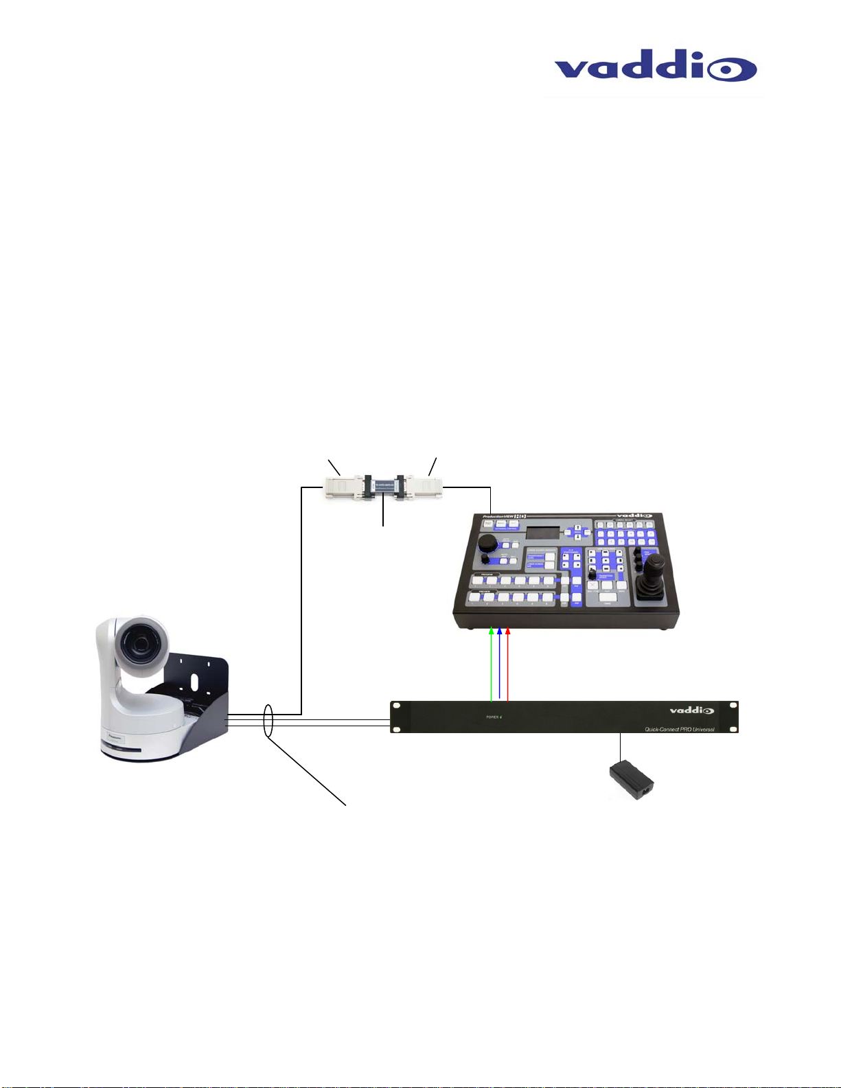
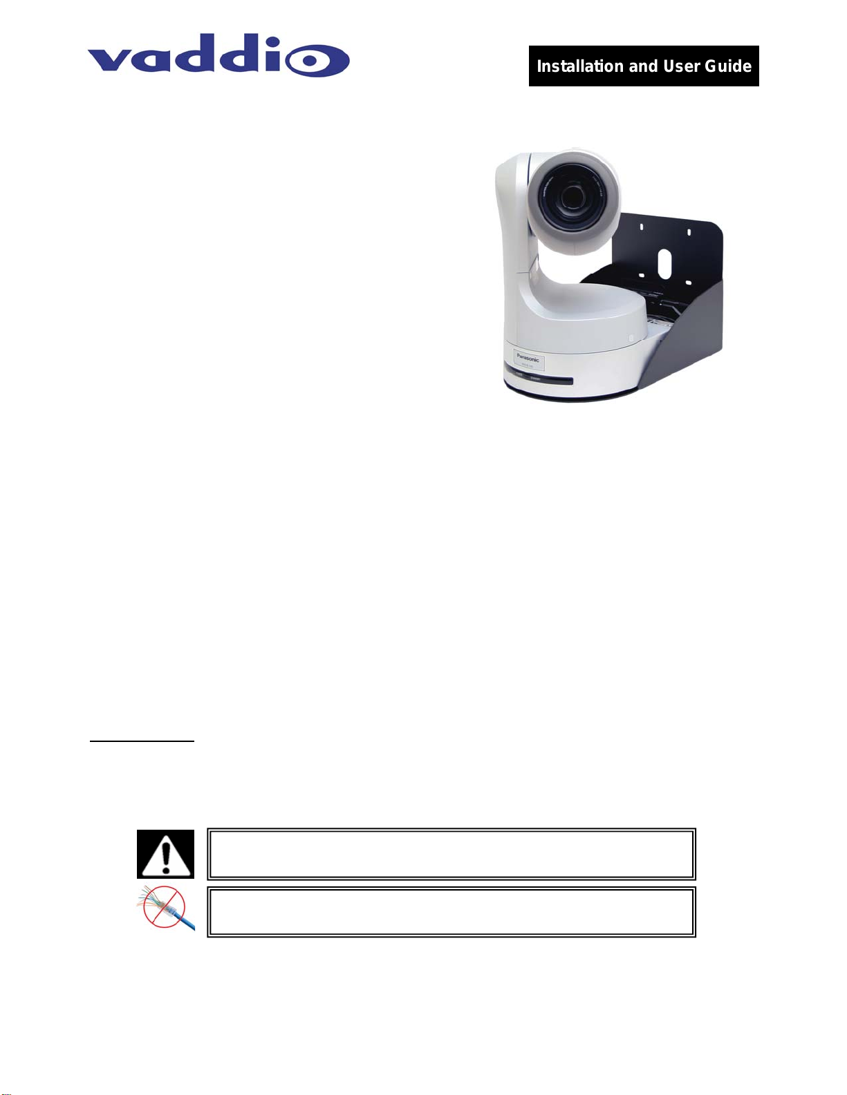
The Vaddio Quick-Connect PRO HE100 (Figure 1) is
built for use with the Panasonic AW-HE100 high
definition PTZ Camera. Vaddio’s WallVIEW PRO HE-
100 camera is designed for easier installation and
integration. In addition, the standard RS-422 is
converted to RS-232 for operation with our complete line
of ProductionVIEW™ PTZ camera controllers and
switchers. The system uses high speed differential
signaling (HSDS), an active transmission system that
delivers low-loss, high-quality video over CAT-5 cabling
distances up to 500’ (152.4m). The system is capable of
high definition (HD) 1080i or 720p component video.
The AW-HE100 comes in either NTSC or PAL formats.
In addition the Quick-Connect PRO system also has auto camera resolution sensing, analog component
video outputs (Y, Pb, Pr), four position distance adjustment for Cat. 5 cabling, Y-Gain adjustment, 1-RU rack
mount Quick-Connect™ PRO System with HSDS, and the EZ Interface Module (EZIM) that fastens to the
back of the camera mount. Like all Vaddio WallVIEW systems, the Thin Profile Wall Mount and mounting
hardware is included.
INTENDED USE
Before installing the Vaddio WallVIEW PRO HE100 Camera System, please read the entire manual
thoroughly. All Vaddio camera systems were designed for use indoors. Outdoor operation is not
recommended, has not been tested, and could damage the camera and/or create a potentially unsafe
operating condition. Use only the Vaddio PowerRite power supply provided.
SAVE THESE INSTRUCTIONS
The information contained in this manual will help you install the Vaddio WallVIEW PRO systems. For
reference, Vaddio keeps copies of Specifications, Installation and User Guides and most pertinent product
drawings for the Vaddio product line on the website. These documents can be downloaded from
www.vaddio.com free of charge.
IMPORTANT SAFEGUARDS
Read and understand all instructions before using. Do not operate any electrical device if it has been
dropped or damaged. In this case, a Vaddio technician must examine the product before operating. To
reduce the risk of electric shock, do not immerse in water and avoid extremely humid conditions.
INFORMATION
For RS-422 control information, please see the full-length Manual for the PANASONIC AW-HE100 posted on
the Vaddio or Panasonic website. Vaddio has also prepared a number of TechNotes, specifications and
drawings designed to inform and educate integrators on the value and the specific uses of Vaddio products.
Figure 1: Quick-Connect PRO HE100 System
with Camera, Wall Mount and EZIM with break
out cable (behind camera)
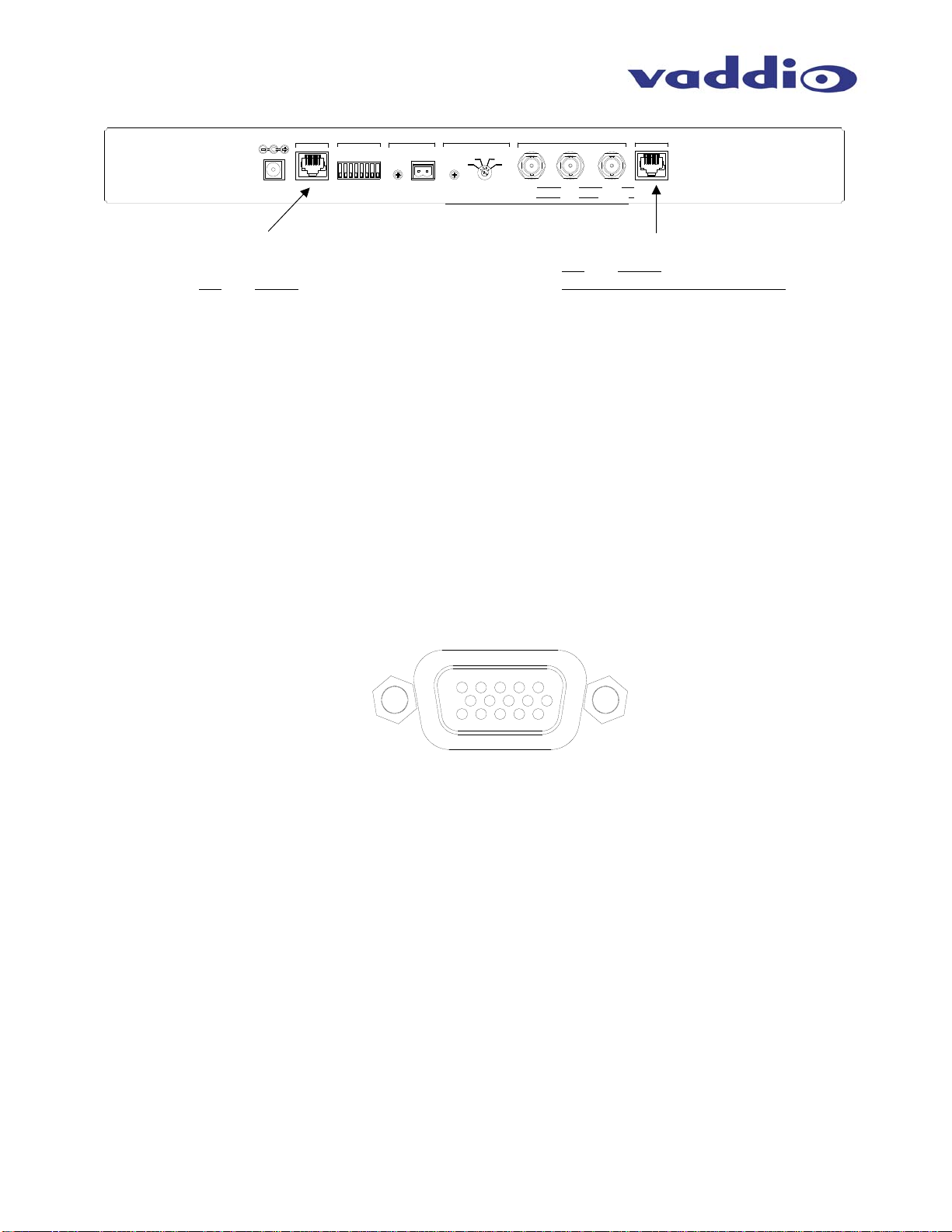
Use only the approved power supplies provided with the system.
Use of any unauthorized power supply will void any and all
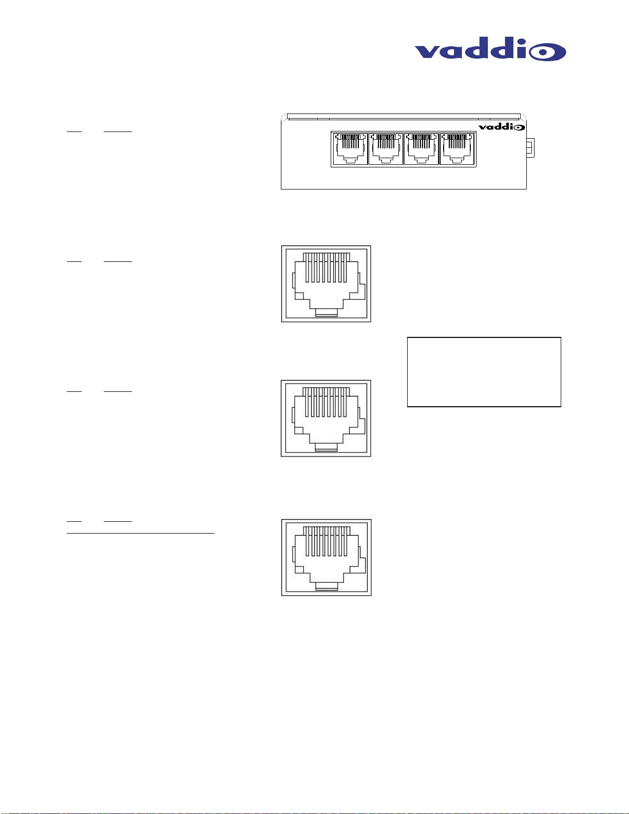
Do not use RJ-45 “pass-thru” connectors. Use standard RJ-45
connectors for best results.

WallVIEW PRO HE100
WallVIEW PRO HE100 Installation and User Guide 341-790 Rev. B Page 2 of 12
UNPACKING
Carefully remove all of the parts from the packaging. Unpack and identify the following parts:
•One (1) Panasonic AW-HE100 –12 VDC Version - with IR Remote
•One (1) Quick-Connect PRO (1-RU) with 2-position Phoenix Type Connector (998-1105-009)
•One (1) EZIM PRO, EZ Interface Module (998-6700-001)
•One (1) HD EZIM Breakout Cable (440-6704-010)
•One (1) CommFront CVT-485_422-1 Port Powered RS-232 to RS-422 Converter
•One (1) DB-9M to Cat 5 RS-232 Adapter (998-1003-000)
•One (1) DB-9F to Cat 5 RS-422 Adapter (998-1005-232)
•One (1) Wall Mount for AW-HE100 (535-2000-229) with Mounting Hardware
•One (1) 36V PowerRite Power Supply with AC Cord Set
•One (1) AC Cord Set for North America
•One (1) 3’ (.91m) Cat 5 Patch Cable (341-192)
•Documentation:
Vaddio Manual
Panasonic AW-HE100 Manual
Optional Accessory: Quick-Connect Boxes for SD video (300 ft. limit) Part # - 998-1105-001 (see p. 5)
Wiring Diagram Example
The Basic Idea:
Figure 2: Basic connectivity of the WallVIEW PRO HE 100 System.
The WallVIEW PRO HE 100 uses a Cat. 5 (all 4-pairs) for power to ensure the direct drive motors receive the required
current to operate properly. The Video Cat. 5 uses 3-pairs of the Cat. 5 for Video. The RS-232/RS-422 Cat. 5 uses three (3)
conductors to the RS-232 to 422 adapter and five (5) conductors for RS-422 control protocols to the camera. The RS-232 to
RS-422 is port powered and it is recommended to be located close to the control source. These Cat. 5 cables can be run up
to 500’ (152.4m). See Appendix 1 for wiring and pin-out information.
Component Video (Y, Pb, Pr)
to HD video switcher
36 VDC PowerRite
Power Supply
WallVIEW PRO HE100 with
Camera, Wall Mount and
EZIM (inside Wall Mount)
Quick-Connect Pro
Rack Mount Interface
Up to 500’ (152.4m) of Cat. 5
for Power, Video and Control
Power Cat. 5
Video Cat. 5
RS-422 Cat. 5 directly
to the RS-422 input on
the AW-HE 100
Camera
ProductionVIEW HD
3 ft. Cat. 5
RS-232
DB9F to RJ-45F
RS-232 to RS-422
Adapter
CommFront
RS- 232 to
RS-422
Converter
RJ-45F to
DB-9M
Adapter

WallVIEW PRO HE100
WallVIEW PRO HE100 Installation and User Guide 341-790 Rev. B Page 3 of 12
INSTALLATION
All WallVIEW products are specifically designed for installation on a vertical wall surface with Cat. 5 cable
connectivity for Power, Video and Control signaling (three cables are required). Installation is simplified in
that no custom 8-Pin mini-din cables or expensive S-Video plenum cables are needed and no power outlets
are required near the camera bracket. All cabling is routed to the head-end using Cat. 5 cables.
Before Installing
•Locate the camera mounting location paying close attention to camera viewing angles, lighting conditions,
possible line of site obstructions, and checking for in-wall obstructions where the camera is to be
mounted. Pick a mounting location to optimize the performance of the camera.
•Pre-wire all cabling as required (see wiring diagram examples).
•The Wall Mount for the WallVIEW PRO HE100 can be mounted directly to a 3-gang wall box or can be
mounted to the drywall using four dry wall anchors.
MOUNTING INSTRUCTIONS
Step 1:
After determining the optimum location of the camera system, route the required 3 (three) Cat. 5 cables from
the camera to the Quick-Connect Pro interface located at the head-end. The three Cat. 5 cables should
feed-through the oval slot located on the rear flange of the wall mount (Figure 4). If the bracket is to be
mounted on a 3-gang wall box, use the screws supplied with the wall box cover plate to attach the Thin
Profile Wall Mount. If mounting to the drywall with wall anchors, use four (4) quality wall anchors. The
mounting holes are slotted and are 90° opposing to provide easy leveling. Level the mount and tighten down
the mounting screws. A fourth Cat. 5 cable is required if simultaneous SD video is desired (see p. 5).
Step 3:
Connect the 25-pin end of the break out cable to the EZIM. Next, mount
the EZIM to the back of the wall mount on the left side, using the two
tapped screw holes (see Figure 4). Connect the 15-pin video cable,
power connector. NOTE: The Cat. 5 cable for RS-422 control is
connected directly to the “Controller” port on the back of the HE 100.
Figure 3:
Thin Profile Wall Mount with oval cable
feed-through hole. The wall mount may be
mounted directly to a 3-gang wall box or to
the dry wall with the appropriate wall
anchors.
Figure 4:
25-pin break out
cable connected to
EZIM (left); EZIM
and break out cable
installed in Wall
Mount (right).
RS-232 IN & OUT are not used with the HE
100. Connect the RS-422 Cat. 5 cable to the
camera’s Controller port.
Mini-DIN 8
Connectors are not
used with the HE 100
Power XLR-4-Pin F
Connector
HD Video - DE-15F
(D-Sub 15-pin HD - F)

WallVIEW PRO HE100
WallVIEW PRO HE100 Installation and User Guide 341-790 Rev. B Page 4 of 12
Step 4:
Attach the Cat. 5 cables for Power and Video to the EZIM. Feed the excess Cat. 5 cable into the wall
opening or wall box. Note: The RS-232 In and Out ports are unused, as the HE-100 uses RS-422 (see
Figure 5).
Step 5:
Place the camera onto the camera mount and using the ¼”-20 screw to secure the camera to the mount.
Step 6:
Assemble the RS-232 to RS-422 converter. There are two RJ-45 to DB-9 adapters, one that has a female
DB-9 and the other has a male DB-9. Connect the DB-9 ends to the RS-232 to RS-422 adapter, and screw
the parts together, using the supplied hardware.
Step 7:
Connect the supplied Cat. 5 cable – approximately 3 feet in length – to the Control port on the
ProductionVIEW controller. Connect the other end of the Cat. 5 cable to the RS-232 end of the protocol
converter (see Figure 5). Connect the RS-422 side of the protocol converter to the Cat. 5 cable that is home-
run to the AW-HE100 Controller port.
Step 8:
The Quick-Connect PRO is a 1-RU rack mount interface that breaks out the signals from the Cat. 5 cables
back to the standard connectors. Set the four position distance adjustment switch to the appropriate length,
based on your Cat. 5 cable run. The basic system connectivity is illustrated in Figure 6.
Figure 6:
Pro Series HSDS
Cable System
Connectivity
Power
Supply IN HD Component
Video Outputs
Power
Cat. 5 Video
Cat. 5
NOTE: The RS-422 Cat.5 cable is connected directly
into the RS-422 CONTROLLER port on the AW-HE100
IR Output – this is
not used with the
AW-HE100 camera
3 ft.
RS-232
Cat. 5
RS-422 Cat. 5
up to 497 feet
Back of AW-HE100
RS-232 to RS-422
Converter
ProductionVIEW HD
Figure 5:
The Cat. 5 cable is connected from back of ProductionVIEW,
through RS-232 to RS-422 converter to AW-HE100
RJ-45F to
DB-9M
RS-232
DB-9F to
RJ-45F
RS-422
RS-422
RJ-45F

WallVIEW PRO HE100
WallVIEW PRO HE100 Installation and User Guide 341-790 Rev. B Page 5 of 12
Step 8 (continued):
Attach the Cat. 5 cables for Power, Video and Control to the Quick-Connect PRO interface. Connect the HD
video output BNC connectors. Connect the PowerRite 36 VDC power supply to the Quick-Connect PRO
power input. Please check all Cat. 5 cables for continuity in advance of final connection.
Note: Plugging the POWER Cat. 5 Cable into the wrong RJ-45 may cause damage to the camera system and void the warranty.
Step 9:
Connect the Vaddio 36 VDC power supply to an AC outlet. Power will travel down the Power Cat. 5 cable to
the cable shoe, powering the camera. The camera will “Home” to a centered position ready for control
information from the IR remote control or RS-232/422 camera controller of the integrators’ choice. NOTE:
To insure proper continuity of control and operation of the cameras, the RS-232 controller (control system or
joystick) should be powered on after the camera.
Step 10:
Follow the instruction manual supplied with the AW-HE100 to set up the camera for the lighting conditions
that the camera is installed in (fluorescent, halogen, etc.), as well as the selected output resolution. The
Quick-Connect PRO is configured to work with the camera delivering component HD 1080i or 720p video.
Adjust the Y-Gain on the back of the Quick-Connect PRO (see Figure 6) for video quality.
Optional Installation for Simultaneous Standard Definition Video:
Standard definition video can be delivered over one additional Cat. 5 cable using two Quick-Connect boxes
(Part # 998-1105-001). Connect a BNC to RCA cable between the Video Out of the camera, and the RCA
input of the Quick-Connect Box. Run a Cat. 5 cable – up to 300 feet – to another Quick-Connect Box.
Connect another video cable between the other Quick-Connect Box and the head end equipment, such as
the video monitor (shown below). No power supplies are required in the configuration below.
Single Cat. 5 Cable
up to 300 feet
BNC to RCA
Composite Video
Cable
BNC to RCA
Composite
Video Cable
Figure 7:
SD video through optional
Quick-Connect boxes and
additional Cat. 5 cable.
PreVIEW Triple 5.6 Standard Definition
Rack Mount LCD Monitors
WallVIEW PRO
HE100 with
Camera, Wall
Mount and EZIM

WallVIEW PRO HE100
WallVIEW PRO HE100 Installation and User Guide 341-790 Rev. B Page 6 of 12
CARE AND CLEANING
•Do not attempt to take the products in these systems apart. There are no user-serviceable components.
•Keep these devices away from food and liquid, and do not spill liquids on the products
•For smears or smudges on the lens, wipe with a clean, soft cloth. Do not use any abrasive chemicals on
the camera body at any time.
OPERATING AND STORAGE CONDITIONS
Do not store or operate the WallVIEW PRO System under the following conditions:
•Temperatures above 40°C (104°F) or below 0°C (32°F), for Indoor Use Only
•High humidity, condensing or wet environments
•Dusty environments
•In inclement weather
•Under severe vibration
GENERAL SPECIFICATIONS
WallVIEW PRO HE100 System
System Part Numbers 999-6105-000 NTSC
999-6105-001 PAL
Quick-Connect Interface
Connectors Power Connector: 5.5mm OD x 2.5mm ID
Power RJ-45: Supplies 36V to EZCamera Interface Module Regulator
IR: 2-Pin Phoenix type spring cage connector
Video Outputs: BNC Connectors for HD Analog Component (Y,PB,PR) or SD
Video RJ-45: Transports HD or SD video from camera depending on camera selection switch position
Camera Select Switch 8-Position DIP switch loads camera profiles and IR Forwarding for Polycom and TANDBERG Codecs
(IR Forwarding Not Available on AW-HE100)
Video Adjustments Y-Gain (luminance gain) for fine tuning over longer cable distances
Distance Compensation: 100’, 200’, 300’, 400’+
Max. Cat. 5 Cable
Distance Up to 500’ (152.4m) for Video Power and Control
Power Supply 36 VDC, 2.78 Amp
Dimensions 1-RU Rack Mount (1.75” H x 19” W x 6” D)
EZCamera Interface Module (EZIM)
Connectors Four (4) RJ-45 Connectors (Note: RS-232 in/out does not work with the AW-HE100 camera)
One DB-25 for Power, Video, Control & IR (IR not available for AW-HE100 camera)
Cable Assemblies For Panasonic HD Cameras: DB-25M to DB-15HD, 4-Pin XLR-F Power Connector
(8-Pin Mini Din x 2 - unused)
Power Regulator Supplies 12VDC to Cameras
Dimensions Approx. (3.035” H x 4.46” W x 1.242” D)
Panasonic AW-HE100 Camera Basic Specifications
Camera Part Number AW-HE100
Signal Systems NTSC or PAL
Video Resolutions HD 1080i or 720p
Lens 13x Optical
Weight Approx. 16.5 lbs. (7.5 kg)
Dimensions Approx 9.375” W x 13.5” H x 10.125” D – excluding protrusions
(238mm x 343.5mm x 257mm) - excluding protrusions

WallVIEW PRO HE100
WallVIEW PRO HE100 Installation and User Guide 341-790 Rev. B Page 7 of 12
Appendix 1: Cable Pin-outs for the WallVIEW PRO System
EZCamera Interface Module Pin-outs
Power Connector
Pin Signal
1 Power +
2 Power -
3 Power +
4 Power -
5 Power +
6 Power -
7 Power +
8 Power -
RS-232 IN Connector
Pin Signal
1) Unused
2) Unused
3) Unused
4) Unused
5) Unused
6) Unused
7) Unused
8) Unused
RS-232 OUT Connector
Pin Signal
1) Unused
2) Unused
3) Unused
4) Unused
5) Unused
6) Unused
7) Unused
8) Unused
Video Connector
Pin Signal
SD HD
1) N/A IR+
2) N/A IR GND
3) N/A Y+
4) N/A PB+
5) N/A PB-
6) N/A Y-
7) N/A PR+
8) N/A PR-
12345678
VIDEOPOWER RS-232
OUT
RS-232
IN
EZIM
12345678
12345678
RS-232 Note:
The Panasonic AW-HE100
camera does use the RS-232
ports on the EZIM and does
not support daisy-chain.

WallVIEW PRO HE100
WallVIEW PRO HE100 Installation and User Guide 341-790 Rev. B Page 8 of 12
EZCamera Interface Module Pin-outs (continued)
DB-25 Connector
Pins Signal
1 GND Out
14 RXD Out
2 TXD Out
15 DTR Out
3 DSR Out
16 GND IN
4 TXD IN
17 RXD IN
5 DTR IN
18 DSR IN
6 IR
19 GND
7 GND
20 CVBS/PR
8 GND
21 C/PB
9 GND
22 Y/Y
10 GND
23 GND
11 GND
24 12V
12 12V
25 12V
13 12V
EZIM Breakout Cable
Part Number 440-6704-010 EZIM for WallVIEW PRO HE100
VIDEOPOWER RS-232
OUT
RS-232
IN
EZIM
DB-25-M
HD Video
DE-15
(D-Sub 15HD-M)
Power
XLR-4-Pin F
8-Pin Mini Din
Connectors
Not used on
WallVIEW PRO
HE100

WallVIEW PRO HE100
WallVIEW PRO HE100 Installation and User Guide 341-790 Rev. B Page 9 of 12
300
200
POWER
36V 2A
>100 400+
Y-GAIN
CAM SELECT
YC
YPB
COMP SD
PR HD
DISTANCE
GND
SIG.
CAMERA IR VIDEO ADJUST VIDEO OUTPUTS VIDEO
IR GAIN
Quick-Connect Pin-outs
Panasonic AW-HE100
Panasonic HD Video (analog component) Pin-outs
Video Output Connector (DB-15HD)
Pin Signal
1 PR
2 Y
3 PB
4 GND
5 GND
6 GND
7 Unused
8 Unused
9 NC
10 Unused
11 Unused
12 Unused
13 Unused
14 Unused
15 Unused
Please See the AW-HE100 Panasonic Owners Manual for all other pin-outs.
Power Connector
Pin Signal
1 Power +
2 Power -
3 Power +
4 Power -
5 Power +
6 Power -
7 Power +
8 Power -
Video Connector
Pin Signal
SD HD
1) N/A N/A
2) N/A N/A
3) N/A Y+
4) N/A PB+
5) N/A PB-
6) N/A Y-
7) N/A PR+
8) N/A PR-
1
6
11
10
5
15

WallVIEW PRO HE100
WallVIEW PRO HE100 Installation and User Guide 341-790 Rev. B Page 10 of 12
FCC, ICES-003 Compliance and CE Declaration of Conformity
FCC Part 15 Compliance
This equipment has been tested and found to comply with the limits for a Class A digital device, pursuant to
Part 15 of the FCC Rules. These limits are designed to provide reasonable protection against harmful
interference when the equipment is operated in a commercial environment. This equipment generates, uses,
and can radiate radio frequency energy and, if not installed and used in accordance with the instruction
manual, may cause harmful interference to radio communications. Operation of this equipment in a
residential area is likely to cause harmful interference in which case the user will be required to correct the
interference at his/her own expense.
Operation is subject to the following two conditions: (1) This device may not cause interference, and (2) This
device must accept any interference including interference that may cause undesired operation of the device.
Changes or modifications not expressly approved by Vaddio can affect emission compliance and could void
the user’s authority to operate this equipment.
ICES-003 Compliance
This digital apparatus does not exceed the Class A limits for radio noise emissions from digital apparatus set
out in the Radio Interference Regulations of the Canadian Department of Communications.
Le présent appareil numérique n’emet pas de bruits radioélectriques dépassant les limites applicables aux
appareils numeriques de la classe A préscrites dans le Règlement sur le brouillage radioélectrique édicte par
le ministère des Communications du Canada.
European Compliance
This product has been evaluated for Electromagnetic Compatibility under the standards for Emissions and
Immunity and meets the requirements for E4 environment. This product complies with Class A (E4
environment). In a domestic environment this product may cause radio interference in which case the user
may be required to take adequate measures.
Standard(s) To Which Conformity Is Declared:
EMC Directive 89/336/EEC
EN 55022A Conducted and Radiated Emissions
EN 55024 Electromagnetic Compatibility - Immunity
EN 61000-4-2 Electrostatic Discharge Requirements
EN 61000-4-3 Radiated Electromagnetic Field Requirement
EN 61000-4-4 Electrical Fast Transients / Burst Requirements
EN 61000-4-5 Surge Requirements
EN 61000-4-6 Conducted Immunity Requirements
EN 61000-4-8 Power Frequency Magnetic Field Requirements
EN 61000-4-11 Voltage Dips, Interrupts and Fluctuations Requirements

WallVIEW PRO HE100
WallVIEW PRO HE100 Installation and User Guide 341-790 Rev. B Page 11 of 12
WARRANTY INFORMATION
Hardware* Warranty - One year limited warranty on all parts. Vaddio warrants this product against defects
in materials and workmanship for a period of one year from the day of purchase from Vaddio. If Vaddio
receives notice of such defects during the warranty period, they will, at their option, repair or replace
products that prove to be defective.
Exclusions - The above warranty shall not apply to defects resulting from: improper or inadequate
maintenance by the customer, customer applied software or interfacing, unauthorized modifications or
misuse, operation outside the normal environmental specifications for the product, use of the incorrect power
supply, improper extension of the power supply cable or improper site operation and maintenance.
Vaddio Customer service – Vaddio will test, repair, or replace the product or products without charge if the
unit is under warranty and is found to be defective. If the product is out of warranty, Vaddio will test then
repair the product or products. The cost of parts and labor charge will be estimated by a technician and
confirmed by the customer prior to repair. All components must be returned for testing as a complete unit.
Vaddio will not accept responsibility for shipment after it has left the premises.
Vaddio Technical support - Vaddio technicians will determine and discuss with the customer the criteria for
repair costs and/or replacement. Vaddio Technical Support can be contacted through one of the following
Return Material Authorization (RMA) number - Before returning a product for repair or replacement,
request an RMA from Vaddio’s technical support. Provide a technician with a return phone number, e-mail
address, shipping address, and product serial numbers and describe the reason for repairs or returns as well
as the date of purchase and proof of purchase. Include your assigned RMA number in all correspondence
with Vaddio. Write your assigned RMA number on the shipping label of the box when returning the product.
Please see Vaddio’s website for current RMA policies and procedures.
Voided warranty – The warranty does not apply if the original serial number has been removed or if the
product has been disassembled or damaged through misuse, accident, modifications, or unauthorized repair.
Cutting the power supply cable on the secondary side (low voltage side) to extend the power to the device
(camera or controller) voids the warranty for that device.
Shipping and handling - Vaddio will not pay for inbound shipping transportation or insurance charges or
accept any responsibility for laws and ordinances from inbound transit. Vaddio will pay for outbound shipping,
transportation, and insurance charges for all items under warranty but will not assume responsibility for loss
and/or damage by the outbound freight carrier. If the return shipment appears damaged, retain the original
boxes and packing material for inspection by the carrier. Contact your carrier immediately.
Products not under warranty - Payment arrangements are required before outbound shipment for all out of
warranty products.
*Vaddio manufactures its hardware products from parts and components that are new or equivalent to new in accordance with industry standard practices.

WallVIEW PRO HE100
WallVIEW PRO HE100 Installation and User Guide 341-790 Rev. B Page 12 of 12
9433 Science Center Drive, Minneapolis, MN 55428
Toll Free: 800-572-2011 ▪Phone: 763-971-4400 ▪FAX: 763-971-4464
www.vaddio.com
©2010 Vaddio - All Rights Reserved. Reproduction in whole or in part without written permission is prohibited. Specifications and pricing
subject to change. Vaddio, WallVIEW, Quick-Connect, EZIM, HSDS and PowerRite are registered trademarks of Vaddio. All other
trademarks are property of their respective owners. Document Number 341-790 Rev. B
This manual suits for next models
2
Table of contents
Other VADDIO Camera Accessories manuals

VADDIO
VADDIO IN-Wall 999-2225-012 User manual

VADDIO
VADDIO WALLVIEW DVI/HDMI HD-20 User manual

VADDIO
VADDIO CCU Image Controller for Canon User manual

VADDIO
VADDIO OneLINK User manual

VADDIO
VADDIO OneLINK HDMI User manual

VADDIO
VADDIO WALLVIEW DVI/HDMI HD-20 User manual

VADDIO
VADDIO Drop Down Series User manual

VADDIO
VADDIO WALLVIEW DVI/HDMI HD-20 User manual

VADDIO
VADDIO WALLVIEW DVI/HDMI HD-20 User manual