VADDIO OneLINK Bridge Instruction Manual

Configuration and Administration Guide for the
OneLINK Bridge
AV Interface
Document 411-0009-32 Rev B
January 2018

ii
Contents
Overview 1
What's in this Guide 2
Features 2
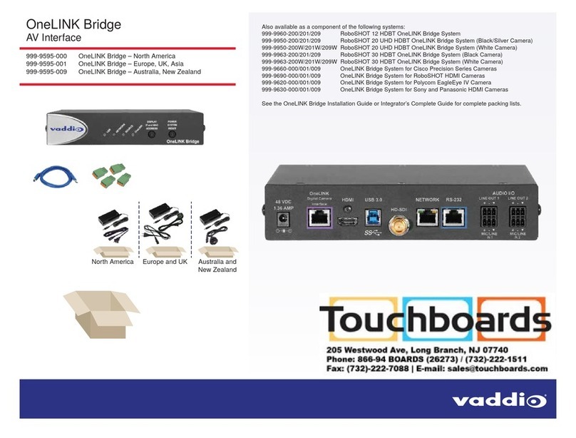
A Quick Look at the OneLINK Device 3
Front Panel of the Receiver 3
Configuration and Administration Tasks 4
Compatible Web Browsers 4
Accessing the Web Interface 5
Web Interface Cheat Sheet 6
Configuring Network Settings 6
Assigning a Hostname 7
Specifying Time Zone and NTP Server 8
Managing Access and Passwords 9
Adding Room Information to the Web Interface 9
Configuring Streaming Settings 10
Enabling Phantom Power to Microphones 11
Configuring Audio Settings 12
Muting the Microphones 12
Controlling Volume on Individual Inputs or Outputs 12
Default Microphone Settings 13
Microphone Settings for Environments with Audiences 14
Microphone Adjustments 15
Speaker Adjustments 16
Preventing Audio Feedback 17
Default Audio Matrix 18
Routing Audio 18
Viewing System Information 19
Saving (Exporting) or Restoring (Importing)a Configuration 19
Rebooting the OneLINK Device 20
Restoring Factory Settings 20
Starting a Firmware Update 21
Contacting Vaddio Technical Support and Viewing Diagnostics 22
Troubleshooting 23
Compliance Statements and Declarations of Conformity 25
OneLINK Bridge AV Interface 25
FCC Part 15 Compliance 25
ICES-003 Compliance 25
European Compliance 26
OneLINK HDMI EZCamera Interface Module (EZIM) 27
FCC Part 15 Compliance 27

1
Overview
This guide covers the OneLINK™ Bridge AV Interface, which is available in the following kit configurations
for use with Vaddio or third-party cameras, with or without third-party codecs.
n999-9595-000/001/009, OneLINK Bridge AV interface
n999-9620-000/001/009, OneLINK Bridge AV interface for Polycom EagleEye IV cameras with Polycom
codecs
n999-9630-000/001/009, OneLINK Bridge AV interfacefor Sony and Panasonic cameras
n999-9560-000/001/009, OneLINK Bridge AV interface for RoboSHOT HDMI cameras with Polycom
codecs
n999-9645-000/001/009, OneLINK Bridge AV interface for Vaddio HDBaseT cameras with Polycom
codecs
n999-9660-000/001/009, OneLINK Bridge AV interface for Cisco cameras with Cisco codecs
n999-9670-000/001/009, OneLINK Bridge AV interface for RoboSHOT HDMI cameras with Cisco
codecs
n999-9675-000/001/009, OneLINK Bridge AV interface for Vaddio HDBaseT cameras with Cisco codecs
n999-9690-000/001, OneLINK Bridge AV interface for RoboSHOT HDMI cameras
The OneLINK Bridge AV interfaceis also available as a component of several Vaddio camera systems.
Part number suffixes indicate power cord set types. Those ending in -000 include cord sets for use in North
America; -001 kits include cord sets for use in Europe and the UK; -009 kits include cord sets for use in
Australia and New Zealand.
If the camera extension is sold for use with an HDMI camera, it is shipped with a OneLINK EZCamera
Interface Module (EZIM).

What's in this Guide
This guide provides information about:
nUnpacking
nPhysical features
nInstallation
nConfiguration and system administration
nTelnet API for third-party control
nSpecifications
nTroubleshooting and maintenance
nWarranty
For your convenience, most of this information is also available in smaller, limited-purpose manuals:
nInstallation Guide for the OneLINK Bridge AV Interface – Unpacking, physical features,
installation, and initial power-on.
nConfiguration and Administration Guide for the OneLINK Bridge AV Interface – Physical
features, web interface for device configuration and system administration, and troubleshooting.
Download manuals, dimensional drawings, and other information from support.vaddio.com.
Features
nConverts any conference room to a BYOD environment, delivering a USB stream for soft-conferencing
clients
nIncorporates Vaddio’s market-leading AV Bridge functionality, connecting professional AV equipment to
PC applications via USB 3.0 media stream
nVideo with audio:Simultaneous uncompressed USB 3.0, HDMI 1.4b, and 3Gb/s HD-SDI; passes IP
stream if available from source
nTwo balanced audio inputs, line level or mic level; two balanced audio outputs, line level
nControl via web interface or Telnet; passes web-based, Telnet, and RS-232 serial control to connected
devices
nSimple, clutter-free camera installation– power, control, video, and streaming over one Cat-5e or better
cable
nExtends installation distance for HDMI and HDBaseT™ cameras up to 100 m (328 ft.)
nCompatible with Vaddio HDBaseT cameras – no EZCamera Interface Module (EZIM) needed
nCompatible with Vaddio and other HDMI cameras
nAvailable in system configurations with Vaddio cameras
nKits available for use with Polycom and Cisco codecs and other HDMI cameras
2
Configuration and Administration Guide for the OneLINK Bridge AV Interface

A Quick Look at the OneLINK Device
This section covers the physical features of the OneLINK Bridge AV interface.
All OneLINK kits include a receiver, which is typically co-located with other equipment, up to 328 ft (100 m)
away from the camera. OneLINK kits for use with HDMI cameras also include an EZCamera Interface
Module (EZIM) HDBaseT converter, which is mounted adjacent to the camera.
Front Panel of the Receiver
nUSB indicator – Illuminates when a USB stream is present.
nNetwork indicator – Illuminates when connected to the IP network.
nSource indicator – Illuminates when a video input is detected.
nOneLINK indicator – Illuminates when the OneLINK Bridge detects a connection to an HDBaseT
device or to the OneLINK EZIM.
nDisplay IP and MAC Address button (illuminated blue) – Outputs the OneLINK Bridge IP and MAC
addresses as an overlay on the HDMI, HD-SDI, and USB video outputs.
nPower System Reset button (illuminated red) – reboots the OneLINK Bridge without affecting the
connected camera.
Note
The OneLINK device does not control the camera; it passes IP and RS-232 traffic to and from the camera.
Use the camera's IP address to access the camera's web interface. The OneLINK device's IP address
only provides access to the OneLINK device, not to the connected camera.
Note
To discover the attached Vaddio camera's IP address, point the IR Remote Commander at the camera and
press the Data Screen button. The camera's IP and MAC addresses are displayed on the connected HDMI
video output.
3
Configuration and Administration Guide for the OneLINK Bridge AV Interface

Configuration and Administration Tasks
The OneLINK Bridge AV interface provides a web interface to allow configuration and administration using
a browser.
The web interface allows password-protected access to tasks such as setting passwords, changing the IP
address, viewing diagnostics, and installing firmware updates.
Note
The OneLINK device is not a camera control device. To configure or operate the camera, use the camera's
web interface. Refer to the camera's documentation for details.
Note
The connected camera is configured separately from the OneLINK device. Changes to the OneLINK
device's configuration do not affect the configuration of the camera or other connected equipment. If you
need to change the way the camera is configured, log in to the camera's web interface.
Compatible Web Browsers
We have tested this product with these web browsers:
nChrome®
nFirefox®
nMicrosoft® Internet Explorer®
nSafari®
We test using the browser version available from the vendor at that time. Older versions of these browsers
are likely to work, and other browsers may also work.
4
Configuration and Administration Guide for the OneLINK Bridge AV Interface

Accessing the Web Interface
To get the IP address:
Press the button labeled Display IP and MAC Address, on the front of the unit. The information is overlaid
on the HDMI, HD-SDI, and USB video outputs.
The OneLINK device will use the default address of 169.254.10.1 if no DHCP server is available. In this
situation, you will need to connect a computer to the OneLINK device's network port and configure network
settings. Depending on the computer, you may need a crossover cable.
To access the web interface:
Enter the IP address or hostname in your browser's address bar. If you use the hostname, you may need to
enter http:// as a prefix to keep the browser from treating it as a search query.
The login page opens. The username admin and the default password is password.
After you log in, the System page opens.
Note
For best security, Vaddio strongly recommends changing the default password. Using default passwords
leaves the product vulnerable to tampering. See Managing Access and Passwords.
5
Configuration and Administration Guide for the OneLINK Bridge AV Interface

Web Interface Cheat Sheet
You must log in to access the pages for all system administration tasks.
Note
The OneLINK device's web interface does not provide access to the connected camera. To configure the
camera, use the camera's web interface, which is at a separate IP address.
What do you need to do? Go to this page
Mute the connected microphone(s) Mute button on all pages
Adjust audio inputs and outputs Audio
Allow conferencing applications to control the audio Streaming
Enable or disable USB streaming Streaming
Find the current firmware version System
Change the Admin password Security
Reboot, restore factory defaults, or run firmware updates System
Add or change information about the room where the equipment is
installed, or the phone number for A/V support
Room Labels
Configure time zone or NTP settings Networking
Specify whether idle sessions close automatically Security
Configure IP addressing Networking
View or change the OneLINK device's hostname Networking
View or change the OneLINK device's USB device name Streaming
Access contact information for Vaddio technical support Help
View or download diagnostic logs for technical support Diagnostics
For your convenience, the navigation panel also provides an elegant Logout button for ending your session
gracefully – and leaving the web interface in a password-protected state.
Configuring Network Settings
NETWORKING PAGE
These settings are for the OneLINK device only. The camera is configured separately.
DHCP addressing is the default setting. In a DHCP environment, you will not need to change the network
configuration.
The OneLINK device will use the default address of 169.254.10.1 if no DHCP server is available. In this
situation, you will need to connect a computer to the OneLINK device's network port and configure network
settings. Depending on the computer, you may need a crossover cable.
Caution
Consult your IT department before changing network settings. Errors in network configuration can make
the OneLINK device and connected equipment inaccessible from the network. Do not change
DHCP/Static addressing, IP address, subnet mask, or gateway unless you are very familiar with the
characteristics and configuration of the network where you install the equipment.
6
Configuration and Administration Guide for the OneLINK Bridge AV Interface
To assign a static IP address:
1. Select static IP addressing.
2. Specify the IP address, subnet mask, and gateway address.
3. Save your changes.
Pro Tip
Make sure you have a way to remember the IP address. There is no hardware factory reset.
Assigning a Hostname
NETWORKING PAGE
The default hostname for the OneLINK BridgeAV interface is the string vaddio-onelink-bridge-
followed by the device's MAC address. You can change this in the Hostname field.
If your network supports hostname resolution, you can browse to the OneLINK device by hostname even if
you cannot readily determine its IP address. In this situation, you may wish to assign a hostname
according to your IT department's naming guidelines.
To edit the hostname:
Enter the desired hostname in the Hostname text box, and save your changes.
7
Configuration and Administration Guide for the OneLINK Bridge AV Interface

Specifying Time Zone and NTP Server
NETWORKING PAGE
To ensure that data exports receive accurate time stamps, and to display the correct date and time on the
Networking page, NTP updating must be enabled.
1. Enable Automatic NTP Updating.
2. Select the desired time zone from the list.
3. If desired, specify the NTP server to use. Otherwise, use the default.
4. Select Refresh to update the displayed date and time.
8
Configuration and Administration Guide for the OneLINK Bridge AV Interface

Managing Access and Passwords
SECURITY PAGE
Things you can do on this screen:
nSet whether inactive sessionslog off automatically or not
nChange the password for the admin account (default is password)
Note
For best security, Vaddio strongly recommends changing passwords from the default. Using default
passwords leaves the product vulnerable to tampering.
Pro Tip
Make sure you have a way to remember the admin password. There is no hardware factory reset.
Adding Room Information to the Web Interface
ROOM LABELS PAGE
On this page, you can provide information about the OneLINK Bridge AV interface's location:
nName of the organization
nName of the room where the equipment is installed
nPhone number of the room where the equipment is installed
nPhone number for the AV or IT support team
This information appears on every page of the OneLINK web interface.
Note
This does not affect the room information (if any) presented on the web interface for the attached camera.
9
Configuration and Administration Guide for the OneLINK Bridge AV Interface

Configuring Streaming Settings
STREAMING PAGE
The camera's settings are used for IP streaming; the OneLINK BridgeAV interface passes the IP stream
from the camera and does not require additional IP streaming configuration.
For non-USB cameras, the OneLINK Bridge AV interface provides USB streaming capability. On the
Streaming page, you can:
nDisable/enable USB streaming
nAllow the conferencing application to control the audio
nEdit the USB device name
After making changes on this page, save them.
To disable or enable streaming:
USB streaming is enabled by default. Use the Enable USB Streaming checkbox to change this.
To control the audio from a computer:
Check the Enabled box for HID Audio Controls.
Note
When HID Audio Controls are enabled, we recommend controlling volume manually. Allowing the
conferencing application to manage the volume automatically can produce undesirable results.
To edit the USB device name:
To change the way the OneLINK device shows up in your soft client's selection list, edit the USB Device
Name.
10
Configuration and Administration Guide for the OneLINK Bridge AV Interface
Enabling Phantom Power to Microphones
AUDIO PAGE, ANALOG TAB
To supply 48 VDC phantom power to a connected microphone, check the Phantom Power checkbox below
the controls for the Line/Mic input.
11
Configuration and Administration Guide for the OneLINK Bridge AV Interface

Configuring Audio Settings
AUDIO PAGE
The web interface provides separate controls for each of the audio inputs and outputs:
nAnalog (Mic/Line In 1 and 2, and Line Out 1 and 2)
nDigital (HDBT Input left and right, HDMI Output left and right, SDI Output left and right)
nStreaming (USB Playback left and right, HDBT Output left and right, USB Record left and right)
The Matrix tab of the Audio page defines audio routing.
Muting the Microphones
Use the Mute control at the top of any page.
Controlling Volume on Individual Inputs or Outputs
AUDIO PAGE, ANALOG, DIGITAL,AND STREAMING TABS
Use the button to mute the desired audio input or output. Use the slider to set the volume.
Note
For best performance with most computers, we recommend setting the USB Record volume high.
12
Configuration and Administration Guide for the OneLINK Bridge AV Interface

Default Microphone Settings
AUDIO PAGE, ANALOG TAB
Acoustic Echo Cancellation – Enabled; prevents audio feedback by cancelling the specified output
signal out of the line/mic input.
Note
If using the OneLINK Bridge with a conferencing codec, ensure that echo cancellation is enabled on only
one device, whether it is the OneLINK Bridge or the codec. If echo cancellation is enabled on both the
OneLINK Bridge and the codec, unexpected audio effects may result. We recommend disabling echo
cancellation on the OneLINK Bridge and allowing the conferencing codec to handle it.
Noise Cancellation – Enabled; suppresses ambient noise.
Automatic Gain Control – Disabled; adjusts gain to compensate for differences in volume as different
people speak.
13
Configuration and Administration Guide for the OneLINK Bridge AV Interface

Microphone Settings for Environments with Audiences
AUDIO PAGE, ANALOG AND MATRIX TABS
Speech Lift: Feeds the signal from the specified microphone to the speakers in the room, so that people in
the back of the room can hear the person who is speaking.
Chairman Override: Gives priority to the specified microphone when more than one person is speaking.
(Matrix tab only)
14
Configuration and Administration Guide for the OneLINK Bridge AV Interface

Microphone Adjustments
AUDIO PAGE, ANALOG TAB
To adjust for more natural speech reproduction:
nHigh-pass filter – Specify the lowest frequency that the microphone should pick up. Use this setting to
reduce low-frequency background noise such as heating/air conditioning systems.
nLow-pass filter – Specify the highest frequency that the microphone should pick up. Use this setting to
reduce hissing sounds and make speech sound natural.
nPEQ (parametric equalizer) – Increase or reduce the volume of specific frequency ranges to
compensate for the audio challenges unique to the situation.
Note
As a best practice, use the equalizer to attenuate undesirable frequency ranges rather than to boost the
desirable frequencies.
15
Configuration and Administration Guide for the OneLINK Bridge AV Interface

Speaker Adjustments
AUDIO PAGE, ANALOG AND STREAMING TABS
To sync the sound with the video:
If the video lags noticeably behind the audio, check the Delay box for the appropriate audio outputs (Analog
or Streaming tab) and enter a delay value in msec. The delay may differ from one output to another.
To compensate for differing speech volumes:
If some people on the far end are inaudible while others are too loud, check the Compressor box to reduce
the dynamic range from the connected speakers. (Analog tab only.)
To compensate for specific audio issues on the far end:
Use the equalizers for the analog outputs to attenuate specific frequency ranges. This can help if the far-
end audio includes unwanted elements such as a rumbling HVAC system or a cricket in the room.
16
Configuration and Administration Guide for the OneLINK Bridge AV Interface

Preventing Audio Feedback
AUDIO PAGE, ANALOG TAB
Audio feedback results when the microphones pick up audio from the speakers.
1. Select Echo Cancellation on any line inputs that are connected to signal sources.
2. In the Global Settings, under Master Output/AEC Reference, select the audio output to use as the
reference - the signal that will be cancelled out of the inputs.
17
Configuration and Administration Guide for the OneLINK Bridge AV Interface
Other manuals for OneLINK Bridge
3
This manual suits for next models
26
Table of contents
Other VADDIO Recording Equipment manuals

VADDIO
VADDIO OneLINK Bridge User manual

VADDIO
VADDIO ADD-A-CAM PRO User manual

VADDIO
VADDIO Quick-Connect USB Mini Instruction Manual

VADDIO
VADDIO OneLINK Bridge User manual

VADDIO
VADDIO EasyTalk 2.0 999-7230-000 User manual

VADDIO
VADDIO WallVIEW HD-18 DVI/HDMI User manual

VADDIO
VADDIO Quick-Connect Universal Cat-5 CCU User manual