Tannoy Vnet User manual

Operation Manual
VNET to Ethernet Interface
ETHERNET
INTERFACE
POWER VNET ETHERNET
EXT PoE D ATA LINK DATA

5 Key Features
Ethernet is a family of computer networking
technologies for local area networks (LANs).
Ethernet was commercially introduced in 1980
and standardized in 1985 as IEEE 802.3. Ethernet
has largely replaced competing wired LAN
technologies.
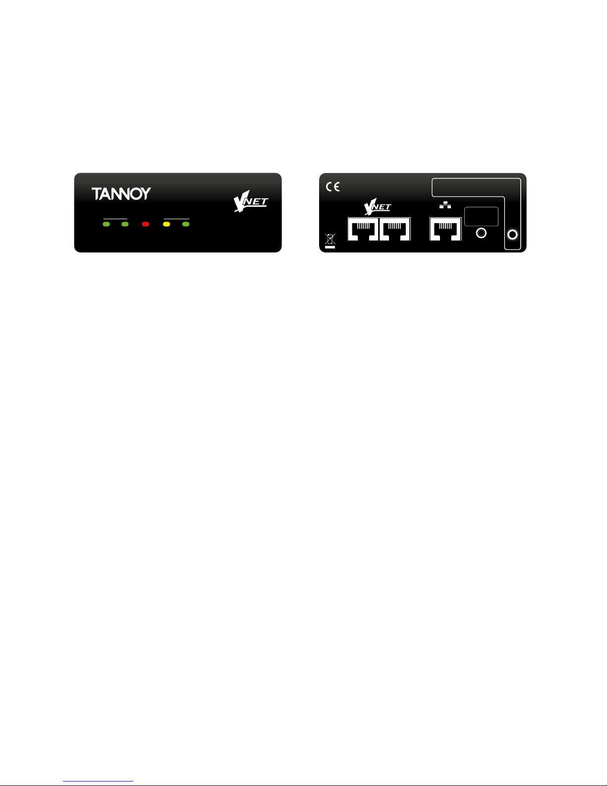
This product allows your Personal Computer
access to a network of VNET enabled devices for
control and monitoring them. It is connected to
your computer or to your network via Ethernet.
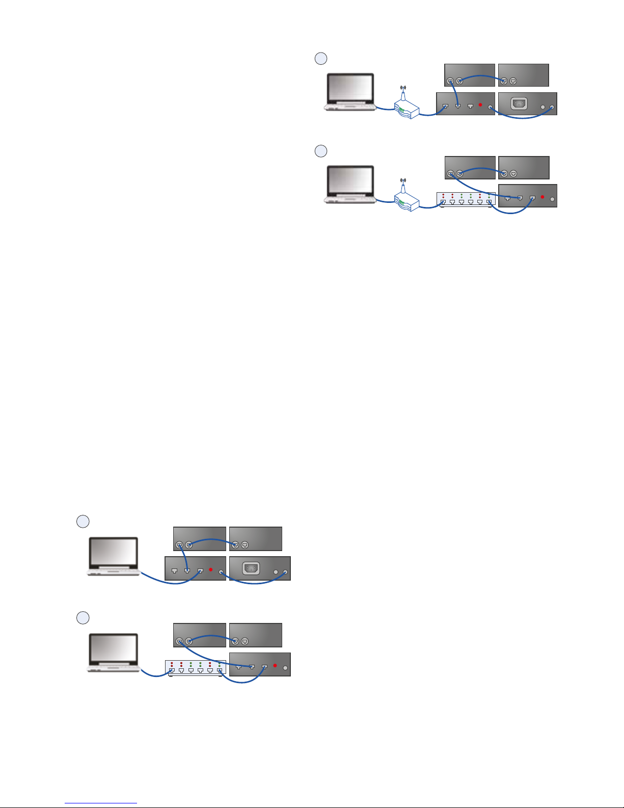
The three primary ways of connecting your
computer to this product are:
1. Direct one to one connection (using auto IP)
2. Through a switch router or hub
3. Through a DHCP router with 802.11g/n for
wireless connection
Housed in a convenient, rugged steel case, it can
be used free-standing or, using the rack-mount
kit, may be racked along with up to two additional
accessory products in 1U rack-space.
• Rugged steel enclosure
• Free-standing or rack-mount options
• Self-powered using Power Over Ethernet (PoE)
• Capable of driving 1km of VNET network cable
• No special cables
6 Computer System
Requirements
Minimum requirements:
• PC with >2 GHz processor
• >2 GB RAM
• 32-bit or 64-bit Windows™ operating system
(XP, Vista, Windows 7, Windows 8).
• CD-ROM drive or Internet access
• Ethernet connection
1 Introduction
Thank you for choosing this product for your
application. Please spare a little time to study the
contents of this operation manual, so that you
obtain the best possible performance from this unit.
2 Important Safety Instructions
Please read carefully and keep the following
instructions and safety information. Heed all
warnings and follow all instructions.
Do not remove covers. There are no user-
servicable parts inside; please refer servicing
to qualied service personnel.
Only use attachments/accessories specied by the
manufacturer.
Servicing is required when the apparatus has been
damaged in any way, such as liquid has been
spilled or objects have fallen into the apparatus, the
apparatus has been exposed to rain or moisture,
does not operate normally, or has been dropped.
3 Regulatory Compliance
This product complies with the EMC Directive
(89/336/EEC) as issued by the Commission of the
European Community.
Compliance with these directives imply conformity
with the following European standards:
• EN55103-1 Electromagnetic Interference
(Emission)
• EN55103-2 Electromagnetic Susceptibility
(Immunity)
This product is intended for operation in the E2
(commercial & light industrial) and E3 (urban
outdoors) Electromagnetic Environments.
4 Unpacking
After unpacking the unit please check carefully
for damage. If damage is found, please notify the
carrier concerned at once. You, the consignee,
must instigate any claim. Please retain all
packaging in case of future re-shipment.

You do not need to worry about IP addressing with
this product. It will by default use DHCP, so your
DHCP server will allocate its IP address. If there is
no DHCP Server, it will use “zero cong”. In either
case, it is fully automatic. For more information
on this topic, please refer to your network
administrator.
10 PodWare Setup
The PodWare application uses a direct connection
via Ethernet to communicate with the connected
devices via the Ethernet Interface.
Using PodWare V6 or later, it should automatically
add a Network Bar in the System View.
You can have multiple Ethernet interfaces
connected to PodWare. The Interfaces will be
transparent to PodWare and the devices will
appear under the appropriate Network Bar in the
System View.
For further information, please refer to Help in
PodWare.
11 Connecting Devices
For VNET devices, connect the VNET Link socket
on the Ethernet Interface to the VNET In socket of
the rst device you wish to control, then the VNET
Link socket of this device to the VNET In socket of
the next device, and so on. The order in which the
devices are connected is not important. The Link
socket of the last device in the ‘chain’ need not be
connected.
1Computer Devices
VNET
In Link
VNET
VNET
In Link
In Link
Ethernet
In
IP Reset
EXT
AB
Ethernet Ethernet
Interface
Power
supply
2Computer Devices
VNET
In Link VNET
In Link
PoE Ethernet
Interface
Power
supply
VNET
In Link
Ethernet
In
IP Reset
EXT
Ethernet
7 Installation
Because the Ethernet interface uses Ethernet, no
installation of drivers is necessary.
However, you will need to check the network
settings on your PC, and install the PodWare
application in order to control and monitor VNET
devices.
8 External Power Supply
This product may be powered from a Power Over
Ethernet (PoE) Ethernet switch. If such a switch is
not available, provision is made to power the unit
from an external VNET interface power supply.
This can power either one or two compatible
accessories. Either the A or the B output on
the Power supply may be used since these are
identical.
9 Connecting a Computer
You can connect your computer to the Ethernet
interface in one of two ways:
1. By direct connection from the Ethernet socket of
your computer to the Ethernet interface
2. By connecting your computer to an Ethernet
Switch, and from the same switch, or from
another switch on the same network, to the
Ethernet interface.
1Computer Devices
VNET
In Link
VNET
VNET
In Link
In Link
Ethernet
In
IP Reset
EXT
AB
Ethernet Ethernet
Interface
Power
supply
2Computer Devices
VNET
In Link VNET
In Link
Ethernet PoE Ethernet
Interface
Power
supply
VNET
In Link
Ethernet
In
IP Reset
EXT

12 Accessory Racking Kit
The Ethernet Interface may be used free-standing
or 19” rack mounted using the optional rack
mounting kit. This kit comprises of a panel which
can accommodate up to three accessories (the
Accessory Power Supply being another example)
in 1U of rack space. Unused positions are neatly
blanked-off. The supplied brackets make the
process of mounting the accessories quick and
easy.
1. Remove the two mounting brackets and Lexan
blanking sheet which are covering the aperture
you wish to mount the Accessory in, by removing
the two nuts. (Keep these and the screws and
washers).
2. Remove the two screws from one side of the
Accessory.
3. Using the two screws removed in 2, attach
one mounting bracket loosely to the side of the
Accessory, with the ‘ear’ towards the front, pointing
outwards.
4. Repeat 2 and 3 for the other side. Now push the
lid towards the back of the unit as far as it will go
then align the bracket ears with the front edge of
the lid. Now tighten the screws.
5. Offer the Accessory with its mounting brackets
up to the reverse side of the Mounting Panel, and
x it in place using the two sets of screws, washers
and nuts removed in 1.
Note that the holes at the rear ends of the brackets
may be used as cable tie-off points if desired.

13 Operation
Once the Ethernet Interface has been connected
to the computer/Switch and to the devices and
if applicable, to the Power Supply, as previously
described, then there are no further adjustments to
make on the unit itself. The indicators on the front
of the unit operate as follows:
ETHERNET
INTERFACE
POWER VNET ETHERNET
EXT PoE D ATA LINK D ATA
The EXT Power indicator will illuminate when DC
power is being applied to the EXT Power socket on
the rear of the unit.
The PoE Power indicator will illuminate when DC
power is being provided by a Power Over Ethernet
(PoE) Switch.
The VNET DATA indicator will illuminate when data
is being received from the VNET network.
The Ethernet Link indicator will icker when the
unit is connected to an Ethernet network.
The Ethernet Data indicator is used to indicate the
following states:
• On – Connected to devices via PodWare
• Rapid blinking – In boot
• Rapid brief ashes – Acquiring IP address
• Slow blinking – Locate feature (or button press
timeout)
• On – Online to PodWare
• Brief ash every 5 seconds – in Static IP mode
The Ethernet DATA indicator will illuminate when
the unit is receiving control data over Ethernet.
The Ethernet RJ45 socket is the Ethernet
connection, which should be connected from your
computer or Ethernet Switch or Router.
The VNET In RJ45 socket is the serial VNET
network connection, which may be used to
connect further VNET devices.
The VNET Link RJ45 socket is the primary serial
VNET network connection, which should be
connected to the rst VNET device in your VNET
network.
The recessed push button is used to set the IP
Addressing mode to the default ‘Auto’ condition by
pressing and holding it for about 10 seconds (until
the Ethernet Data Indicator ashes. For special
maintenance purposes, your vendor may also ask
you to enter ‘Boot’ mode by pressing and holding
this button while the Interface is powering up.
The Ext 3.5mm Jack socket is used for applying
external power to the Ethernet interface. Use only
an approved DC power source. If you are using a
PoE Switch, then no connection need be made to
this connector.
Manufactured in the United Kingdom NOTE: External power is required if PoE is
not available. Use only approved supplies.
EXT
PSU
Press for 5 secs
to reset IP
IEEE 802.3afLINKIN
ETHERNET

14 Troubleshooting
The EXT Power indicator does not illuminate
If you do not have a connection to a PoE Ethernet
Switch, you need to use the Accessory Power
Supply.
• Make sure this is connected properly.
• Check if the power indicator on the Power
Supply illuminates.
• If instead you are using a PoE Ethernet Switch,
it is not usually necessary for an external power
supply to be used, in which case this indicator
will not illuminate.
PodWare does not nd the Interface
• Check that the Ethernet Data indicator ashes to
indicate that there is an Ethernet connection.
• Make sure the Ethernet network cable is not too
long, is correctly connected, and is not damaged.
• Make sure the Interface does not have a Static IP
address.
• Turn off the wireless port on your computer.
• Check if any rewall is blocking PodWare from
accessing the network.
PodWare nds no devices
• Can you see a Ethernet Interface Network Bar in
PodWare?
• Are the appropriate indicators illuminated?
(See above).
• Make sure the VNET network cabling is not too
long, is correctly connected, and is not damaged
and conforms to Application Note DQ2707.
• Check that the VNET Data indicator ashes
when PodWare attempts to go online. If not,
there may be a problem with the VNET cabling.
15 Network Properties
To access the below panel, right click on the
Ethernet Interface Network you wish to access and
click properties.
EtherBridge Network Properties
Ethernet VNET Interface
Device Information
Host Name
IP Address
MAC Address
Boot Version
Firmware Version
Ethernet Mode
VNET Rx
VNET Tx
Online
Network Name
Use Autolp
Use Static IP
Static Address
EtherBridge455B
Device Configuration
EtherBridge
169.254.163.140
1E-30-6C-A2-45-5B
1.080
1.120
100mbs - FDX
0 Frames
0 Frames
Locate
Apply
Browse... Update
192.168.0.222
Firmware Update
• Device Information displays the Host Name,
current IP Address, Firmware/Boot versions,
Mac Address and the Online status
• Locate button - The locate button ashes
Ethernet data indicator on the Ethernet Interface
to show which Ethernet Interface you are online to.
• AutoIP/Static IP radio buttons - Indicates the
type of IP addressing and IP address that the
static will be set to. Note: Static IP should not
normally be used since this could easily result
in duplicate IP addresses, addresses out of
range, or addresses which are not compatible
with your computer settings. Most networks
are setup in an ad hoc basis and setting static IP
addresses will prevent the DHCP server
assigning a known available IP address.
• Apply button - Sets conguration of IP setting
and network name changes.
• Firmware Update - Browse to locate update
le and click update to load rmware le in to the
Ethernet Interface.

16 Technical Specifications
VNET
Cable type Category 5 UTP
(or better)
Ethernet
Speed 100/1000 base T
Connector Standard RJ45
Overall
Weight 500 g
Power External 12v DC1)
or PoE (5 W max)
Case Steel
Notes:
1. Use only approved power supplies.
A full range of measurements, performance data,
can be downloaded from www.tannoypro.com. For
project-specic system design assistance, contact
the AET group via www.aetgroup.tc
Tannoy operates a policy of continuous research and
development. The introduction of new materials or
manufacturing methods will always equal or exceed
the published specications. All specications are
subject to change without notice
VNET is a trademark of Tannoy Limited. All other
trademarks remain the property of their respective
owners.
Copyright (c) 2014 Tannoy Limited. All rights reserved.

tannoypro.com
Tannoy operates a policy of continuous research and development. The introduction of new materials or
manufacturing methods will always equal or exceed the published specications. All specications are
subject to change without notice. Copyright (c) 2015 Music Group Innovation SC Ltd. All rights reserved.
6481 0658 / 231115
Table of contents
Other Tannoy Recording Equipment manuals