Hioki 8205-10 User manual

8205-10
MICRO HiCORDER
July 2013 Revised edition 10 8205B981-10 13-07H
Instruction Manual


Contents
Introduction i
Inspection i
Safety Notes ii
Notes on Use v
Chapter Summary viii
Chapter 1 Product Overview 1
1.1 Product Overview 2
1.2 Features 3
1.3 Front Panel 4
1.4 LCD (Display) 6
1.5 Printout Information 7
Chapter 2 Measurement Procedures 9
2.1 Preparations 9
2.2 DC Voltage Measurement 13
2.3 AC Voltage Measurement 17
2.4 AC Current Measurement 1 21
2.5 AC Current Measurement 2 25
2.5.1 When Measuring High Voltage and High
Frequency Signals 30
2.6 AC Current Measurement 3 31
2.7 Common Measurement Operations 33
Chapter 3 Changing the Recording Paper 37
3.1 Opening and Closing the Printer Cover 37
3.2 Installing Recording Paper 38

Chapter 4 Specifications 39
4.1 General Specifications 39
4.2 Voltage Measurement Input Specifications 41
4.3 Current Measurement Input Specifications 42
4.4 Display Specifications 43
4.5 Recorded Information 44
4.6 Recording Time 44
Chapter 5 Maintenance and Service 45
5.1 Storage Precautions 45
5.2 Cleaning 46
5.3 Cleaning the Printer Head 47
5.4 Service 48

i
_____________________________________________________________________
Inspection
______________________________________________________________
Introduction
Ins
p
ection
Thank you for purchasing the Hioki 8205-10 MICRO
HiCORDER. To obtain maximum performance from the
instrument, please read this manual first, and keep it handy
for future reference.
When you receive the instrument, inspect it carefully to
ensure that no damage occurred during shipping. In
particular, check the accessories, panel switches, and
connectors. If damage is evident, or if it fails to operate
according to the specifications, contact your dealer or Hioki
representative.
Accessories
9344 CARRYING CASE 1
L9257 CONNECTION CORD 1
9235 RECORDING PAPER (15 m) 1
Roll Paper Spools 2
AC Power Cord 1
Instruction Manual 1
Options
9235 RECORDING PAPER (15 m, 10 rolls) 1
9236-01 RECORDING PAPER
(15 m, Climate-resistant; 10 rolls) 1
9650 CLAMP ON SENSOR 1
9651 CLAMP ON SENSOR 1
9667 FLEXIBLE CLAMP ON SENSOR*1
9668 CLAMP ON SENSOR 1
*: A separate conversion adapter is also necessary.
Contact your dealer or Hioki representative.

ii
_____________________________________________________________________
Safety Notes
______________________________________________________________
DANGE
R
This instrument is designed to conform to IEC 61010
Safety Standards, and has been thoroughly tested for
safety prior to shipment. However, mishandling
during use could result in injury or death, as well as
damage to the instrument. Be certain that you
understand the instructions and precautions in the
manual before use. We disclaim any responsibility for
accidents or injuries not resulting directly from
product defects.
Safety Symbols
The symbol printed on the instrument indicates that
the user should refer to a corresponding topic in the
manual (marked with the symbol) before using the
relevant function.
In the manual, the symbol indicates particularly
important information that the user should read before
using the instrument.
Indicates a grounding terminal.
Indicates DC (Direct Current).
Indicates AC (Alternating Current).
Indicates both DC (Direct Current) and AC (Alternating
Current).
Indicates the ON side of the power switch.
Indicates the OFF side of the power switch.
Safet
y
Notes
This manual contains information and warnings essential
for safe operation of the instrument and for maintaining it
in safe operating condition. Before using the instrument,
be sure to carefully read the following safety notes.

iii
_____________________________________________________________________
Safety Notes
______________________________________________________________
DANGE
R
Indicates that incorrect operation presents an extreme
hazard that could result in serious injury or death to
the user.
WARNING
Indicates that incorrect operation presents a
significant hazard that could result in serious injury or
death to the user.
CAUTION Indicates that incorrect operation presents a
possibility of injury to the user or damage to the
instrument.
NOTE Advisory items related to performance or correct
operation of the instrument.
f.s. (maximum display or scale value, or length of scale)
Signifies the maximum display (scale) value or the length
of the scale (in cases where the scale consists of unequal
increments or where the maximum value cannot be
defined).
In general, this is the range value (the value written on
the range selector or equivalent) currently in use.
The following symbols in this manual indicate the relative
importance of cautions and warnings.
Accuracy
We define measurement tolerances in terms of f.s. (full
scale) values, with the following meanings:

iv
_____________________________________________________________________
Safety Notes
______________________________________________________________
CATII Primary electrical circuits in equipment connected to an
AC electrical outlet by a power cord (portable tools,
household appliances, etc.)
CAT II covers directly measuring electrical outlet
receptacles.
CATIII Primary electrical circuits of heavy equipment (fixed
installations) connected directly to the distribution panel,
and feeders from the distribution panel to outlets.
CATIV The circuit from the service drop to the service entrance,
and to the power meter and primary overcurrent
protection device (distribution panel).
Measurement categories
This instrument complies with CAT III safety requirements.
To ensure safe operation of measurement instruments, IEC
61010 establishes safety standards for various electrical
environments, categorized as CAT II to CAT IV, and called
measurement categories. These are defined as follows.
Using a measurement instrument in an environment
designated with a higher-numbered category than that for
which the instrument is rated could result in a severe
accident, and must be carefully avoided.
Use of a measurement instrument that is not CAT-rated in
CAT II to CAT IV measurement applications could result in
a severe accident, and must be carefully avoided.

v
_____________________________________________________________________
Notes on Use
______________________________________________________________
DANGE
R
The maximum input voltage is 500 V DC/AC. Attempting
to measure voltage in excess of the maximum input
voltage could destroy the instrument and result in
personal injure or death.
The maximum rated voltage between input terminals
and ground is 500 V DC/500 VrmsAC. Attempting to
measure voltages exceeding 500 V with respect to
ground could damage the instrument and result in
personal injury.
Connection cords or clamp-on sensor should be made
only at the secondary side of a breaker, so the breaker
can prevent an accident if a short circuit occurs.
Connections should never be made to the primary side
of a breaker, because unrestricted current flow could
cause a serious accident if a short circuit occurs.
To avoid short circuits and potentially life-threatening
hazards, never attach the clamp to a circuit that
operates at more than the maximum rated voltage, or
over bare conductors.
WARNING
To avoid electric shock, do not allow the instrument to
get wet, and do not use it when your hands are wet.
To avoid electric accidents and to maintain the safety
specifications of this instrument, connect the power
cord provided only to a 3-contact (two-conductor +
ground) outlet.
To avoid electric shock when measuring live lines,
wear appropriate protective gear, such as insulated
rubber gloves, boots and a safety helmet.
Do not use the product where it may be exposed to
corrosive or combustible gases. The product may be
damaged or cause an explosion.
Notes on Use
Follow these precautions to ensure safe operation and to
obtain the full benefits of the various functions.

vi
_____________________________________________________________________
Notes on Use
______________________________________________________________
CAUTION This instrument is designed for indoor use, and operates
reliably from 5 to 40℃.
Do not store or use the instrument where it could be
exposed to direct sunlight, high temperature or humidity, or
condensation. Under such conditions, the instrument may
be damaged and insulation may deteriorate so that it no
longer meets specifications.
This instrument is not designed to be entirely water- or
dust-proof. To avoid damage, do not use it in a wet or
dusty environment.
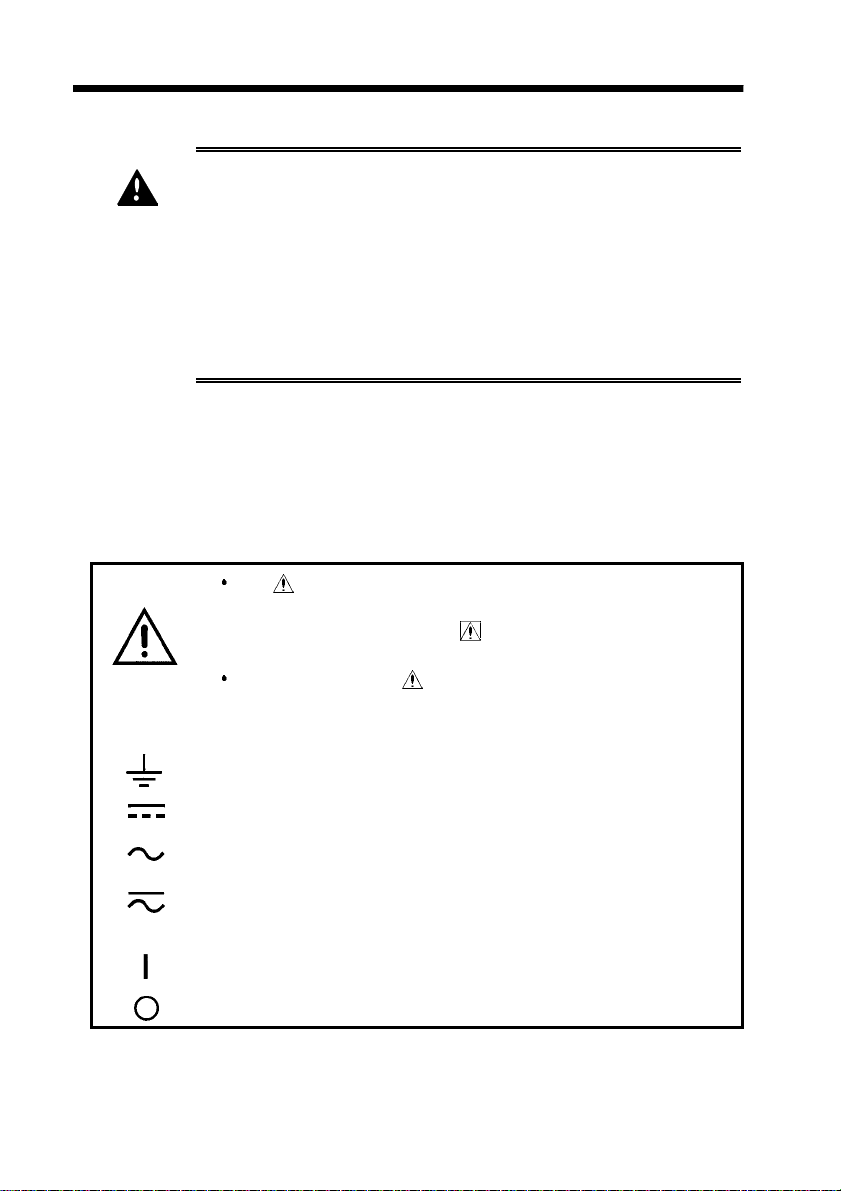
To operate from DC power, pay careful attention to polarity
when making power connections, and set the power source
switch to the DC position ( ) before use. Also, before
changing the power source, unplug the ( ) power cord
from the outlet to prevent hazards, and remove the
connection cord from any object under test.
Avoid stepping on or pinching the cable, which could
damage the cable insulation.
Keep the cables well away from heat sources, as bare
conductors could be exposed if the insulation melts.
To prevent an electric shock accident, confirm that the
white or red portion (insulation layer) inside the cable is not
exposed. If a color inside the cable is exposed, do not use
the cable.
Be careful to avoid dropping the clamps or otherwise
subjecting them to mechanical shock, which could damage
the mating surfaces of the core and adversely affect
measurement.
Keep the clamp jaws and core slits free from foreign
objects, which could interfere with clamping action.
For shipping or long-term storage, be certain that the
recording head is in the raised position. Otherwise the
rollers could be deformed and cause uneven printing.

vii
_____________________________________________________________________
Notes on Use
______________________________________________________________
NOTE Use only recording paper specified by Hioki. Non-specified
recording paper may result in poor-quality or blank printouts.
Avoid using the printer in hot, humid environments, as this can
greatly reduce printer life.
Accurate measurement may be impossible in the presence of
strong magnetic fields, such as near transformers and high-
current conductors, or in the presence of strong electromagnetic
fields such as near radio transmitters.
This instrument may cause interference if used in residential
areas. Such use must be avoided unless the user takes special
measures to reduce electromagnetic emissions to prevent
interference to the reception of radio and television broadcasts.
WARNING
Before using the instrument, make sure that the
insulation on the connection cords is undamaged and
that no bare conductors are improperly exposed.
Using the instrument in such conditions could cause
an electric shock, so contact your dealer or Hioki
representative for repair.
Before Use
Before using the instrument the first time, verify that it
operates normally to ensure that the no damage occurred
during storage or shipping. If you find any damage, contact
your dealer or Hioki representative.

viii
_____________________________________________________________________
Chapter Summary
______________________________________________________________
Cha
p
ter Summar
y
This manual consists of the following chapters.
"Introduction", "Safety Notes", "Notes on Use" describe
precautions on use, overview, and features of this unit.
Be sure to read them all. Next, check Chapter 1 to 5 and
the unit to confirm your understanding of the function.
Chapter 1 Product Overview
Outlines the product and explains the names and functions
of its parts.
Chapter 2 Measurement Procedures
Explains procedures for measurement using the product.
Chapter 3 Changing the Recording Paper
Explains how to replace the recording paper.
Chapter 4 Specifications
Sets forth specifications of the product.
Chapter 5 Maintenance and Service
Provides information maintenance and service information
for the product.

1
_____________________________________________________________________
Product Overview
______________________________________________________________
Chapter 1
Product Overview

2
_____________________________________________________________________
Product Overview
______________________________________________________________
1.1 Product Overview
The multi-functional recording Model 8205-10 MICRO
HiCORDER is almost as easy to use as a simple DMM.
A broad range of applications, from small-signal electronic
circuitry to commercial power circuits, are supported by
wide AC and DC voltage measurement ranges covering 0.1
to 500 volts, a graduated analog-style amplitude display and
current measurement functions when used with an optional
clamp-on sensor.

3
_____________________________________________________________________
Product Overview
______________________________________________________________
1.2 Features
(1) Easy operation
The large single-function controls allow operation without
requiring repeated reference to the manual.
(2) Graduated analog-style amplitude display
The high-resolution graduated display and data display
matching the selected range allow input signal levels to be
viewed like an analog meter.
(3) Recording paper printout
Setup conditions for recorded data and elapsed time are
printed out with recorded measurements, eliminating the
need for complex multiple printouts for record storage and
reporting.
(4) Wide measurement ranges
The 0.1 to 500-V AC and DC ranges support a wide variety
of applications, and optional clamp-on sensors are available
to measure current.
(5) True rms display
The true effective-value conversion circuitry provides
accurate measurements, even of distorted waveforms.
(6) Dual power supply system
Power can be supplied from either the AC mains or a 12-V
DC source. AC mains supply voltages between 100 to 240
V AC are automatically selected.
(7) Handy carrying case
The supplied carrying case includes storage for the power
cord and recording paper.

4
_____________________________________________________________________
Product Overview
______________________________________________________________
Printer Cover
POSITION Control
PAPER FEED
Button
ADJ Button
CHART Button
A (CLAMP)
Selector
SPEED Selector
FUNCTION Switch
RANGE Selector
Test Voltage Input
Terminals
AC Connector POWER Switch
Clamp Terminals
POWER SOURCE Switch
LCD (display)
DC Terminals (DC Power Source)
GND Terminal
Indicator
1.3 Front Panel

5
_____________________________________________________________________
Product Overview
______________________________________________________________
LCD (display) Displays the signal level and device status, including
selected mode and range, numeric scale values, and
indicators. States such as print head up, out of paper
and low supply voltage are also displayed.
PAPER FEED Button Manually advances the recording paper
Pressing this button momentarily advances the paper
about 30 mm. Holding this button advances the paper
continuously.
ADJ Button Adjusts the zero-reference point for measurements
Indicator This indicator lights when the CHART button is in the
START state, and blinks when the print head is up
and at paper end (in the START state).
CHART Button Starts and stops recording
A (CLAMP) Selector Selects input sensitivity to match a connected clamp-
on sensor (when used), and applies that sensitivity
internally so that the range setting prints appropriately
on the recording paper
Clamp Terminals Connect a clamp-on sensor to these terminals to
measure current
Test Voltage Input
Terminals Apply the test voltage across these terminals for
measurement
RANGE Selector Selects the measurement signal type and amplitude
range. Daisabled for A ranges.
FUNCTION Switch Selects AC or DC measurement
SPEED Selector Sets the transport speed of the recording paper
POSITION Control Sets the relative display position of the numeric scale
marks for measuring input signals, and the DC offset (for
DC measurements). Daisabled for A and ACV ranges.
Printer Cover Covers the printer mechanism and recording paper
storage
POWER SOURCE
Switch Selects whether the recorder is to be powered from
AC mains, or DC
AC Connector Connect the AC cord here to operate the recorder
from commercial power (100 to 240 V AC)
DC Terminals (DC
Power Source) Connect a 12-V (nominal) DC supply to these
terminals to operate the recorder from DC power
GND Terminal This is a signal reference ground to establish a
reference for eliminating stray effects such as noise
from measurements
POWER Switch Turns the recorder on an off

6
_____________________________________________________________________
Product Overview
______________________________________________________________
Under-range Indicator
Pointer
Over-range Indicator
Low (DC) Supply Voltage
Indicator
Numeric Display
Paper End Indicator
Scale
Print Head Up Indicator
Positive
Negative
Over-range Indicator This arrow lights when the input signal exceeds the
upper limit of the selected range (the highest level
segment lights at the same time).
Pointer The input signal level is indicated by the lit segment
(pointer) in the graduated bar-type scale
Under-range Indicator This arrow lights when the input is below the lower
limit of the selected range (the lowest level segment
lights at the same time).
Low (DC) Supply
Voltage Indicator Lights when the DC supply voltage is low.
Numeric Display These numeric values are the amplitude values of the
gradations on the meter scale, according to the
selected range (six 3-digit, 7-segment numerals plus
decimal point)
Paper End Indicator Lights when no recording paper is present.
Scale This graduated scale contains the pointer (lit
segment) that indicates the input signal level.
Print Head Up
Indicator Lights when the print head is raised.
1.4 LCD (Display)

7
_____________________________________________________________________
Product Overview
______________________________________________________________
Recording
Waveform
T
rademark
Model
Scale
Setup Range Data 1
Elapsed Time Display
Printing Waveform Setup Range Data 2Interval Printing
Setup Range Data 1 The print setup signal type, numeric value of the
range and display units are printed once when the
CHART button is pushed (ON).
Model Prints when the CHART button is pushed (ON)
Trademark Prints when the CHART button is pushed (ON)
Scale Prints when the CHART button is pushed (ON)
Elapsed Time Display Prints at 5-division intervals
Setup Range Data 2 Prints at 10-division intervals, and when the range
setting or position control is changed.
Interval Printing
(numeric amplitude) The input signal amplitude is printed numerically at
specific intervals. If the measurable range is widely
over range, the following indications will appear.
DC mode
OVER(+): Indicates the amplitude is over range (positive side).
OVER(-): Indicates the amplitude is over range (negative side).
AC, Current mode
OVER(+): Indicates the amplitude is over range.
Printing Waveform Prints when the average mode is selected.
Unaverage mode: DC, Average mode: DC
ADJ Data See Section 2.7, Item 9 regarding ADJ button
1.5 Printout Information
Example of DC-5 V range case

8
_____________________________________________________________________
Product Overview
______________________________________________________________
NOTE When the printing speed is set to 20 cm/min (maximum), the
recording waveform prints lightly.
Table of contents
Other Hioki Recording Equipment manuals

Hioki
Hioki 9518-02 User manual

Hioki
Hioki RS-232C User manual

Hioki
Hioki 8860 User manual

Hioki
Hioki Memory HiCorder MR6000 Instruction manual

Hioki
Hioki 3920-01 User manual

Hioki
Hioki 3909 User manual

Hioki
Hioki Memory HiCorder MR6000 Instruction manual

Hioki
Hioki 9588 User manual

Hioki
Hioki MR8847A User manual

Hioki
Hioki 9593-03 User manual