Customer Clinic
Presentation
We share a wide variety of
information, tips, tricks and
troubleshooting at our customer
clinics.
In case you missed anything you
can view the presentation at any
time by following the QR code to
the right.
View Presentation
Seed Hawk Cheat Sheets
To ensure you have the right
information at your fingertips
when you need it, we have created
a folder of cheat sheets, tips,
tricks, trouble shooting, and a
copy of this Start Guide.
Follow the QR code to the right
to view the folder and download
the files to your iPad or phone for
quick, easy access in the field.
View Folder Contents
QuickStart Videos
We have laid out the steps for
many of the main functions of your
Seed Hawk seeding system in this
guide, to get you started with your
new machine.
Follow the QR code to the right
to view all Seed Hawk QuickStart
videos.
View Folder Contents
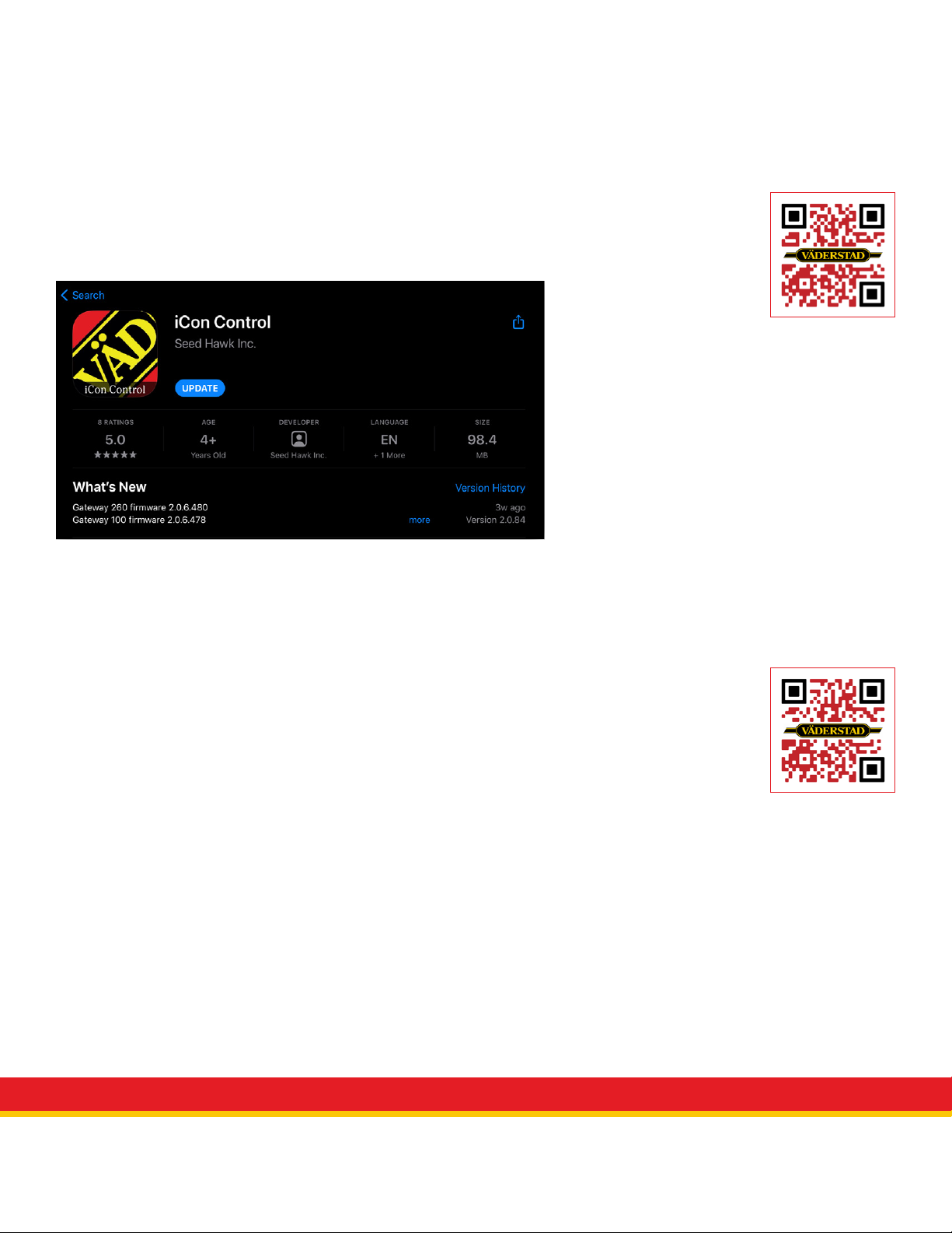
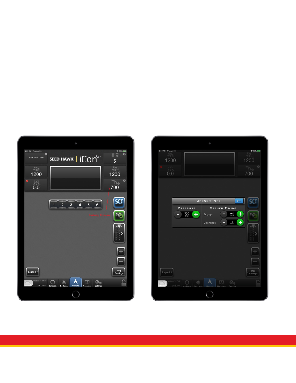
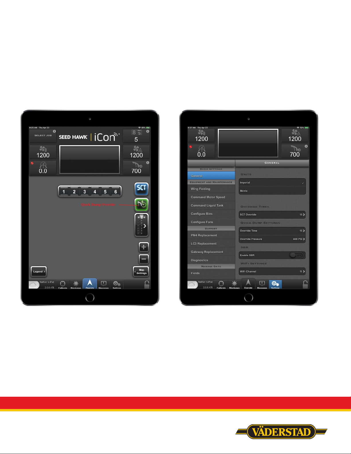
Seed Hawk iCon Control
The modern iPad-based control
system Seed Hawk iCon Control
provides simple, complete control
of your Seed Hawk air cart and
toolbar.
Wireless control provides
substantial benefits for seed
drill systems. Carry your iCon
controlled tablet with you to gain
full seeder control and eliminate
the need to go back and forth
between the tractor cab and the
machine.
View App in Store
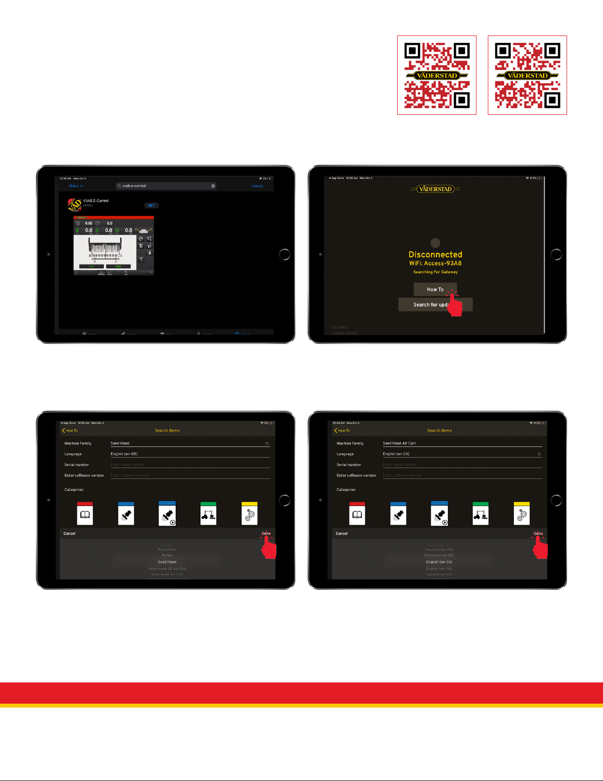
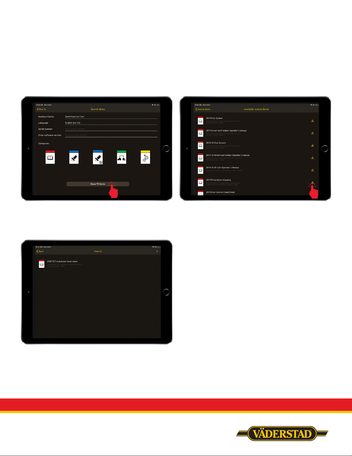
Vaderstad E-Control
The modern iPad-based control
system Väderstad E-Control can
be used to download manuals,
instructions and QuickStarts to be
stored for offline use on your iPad.
View App in Store