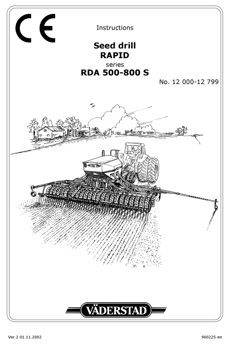
Vaderstad RAPID RDA S Series User manual

Ver.3 29/06/07 900236-dk
Instruktioner
Såmaskine
RAPID
serie
RDA 600-800 S
Nr. 12 800-14 799

2 Ver.3 29/06/07

Ver.3 29/06/07 3
1 Safety regulations
1.1 Before using the drill ............................................................................ 6
1.2 arning decals ................................................................................... 6
1.3 Other safety precautions ...................................................................... 8
1.4 Location of warning decals on the machine ............................................. 9
1.5 Data plates ......................................................................................... 9
2 Instructions and settings
2.1 Tractor ............................................................................................. 10
2.2 Inspecting the drill's towing eyelet ....................................................... 11
2.3 Installation of the Control Station on the tractor .................................... 12
2.4 Hitching and unhitching the seed drill ................................................... 13
2.5 Adjusting hose length and connecting intermediate cable ........................ 15
2.6 heel retraction mechanism ............................................................... 16
2.7 Switching between transport and working modes ................................... 18
2.8 Horizontal alignment .......................................................................... 20
2.9 Adjusting sowing depth ...................................................................... 22
2.10 Adjusting weight transfer .................................................................... 23
2.11 Adjusting the changeover valve ........................................................... 24
2.12 Adjustment of the pre-implements ....................................................... 25
2.13 Setting the radar ............................................................................... 29
2.14 Setting the seed rate, mechanical feed output ....................................... 30
2.15 Seed box settings with hydraulic feed output ......................................... 30
2.16 Calibration, mechanical feed output ..................................................... 31
2.17 Calibration, hydraulic feed output ........................................................ 33
2.18 Prior to filling the hopper .................................................................... 38
2.19 Operation test ................................................................................... 40
2.20 Emptying the seed hopper .................................................................. 40
2.21 Adjusting the air-flow ......................................................................... 41
2.22 Control station .................................................................................. 42
2.23 Tramlining ........................................................................................ 56
2.24 Adjusting the pre-emergence bout marker ............................................ 57
2.25 Adjusting the following harrow ............................................................ 58
2.26 Adjusting Low lift height ..................................................................... 59
2.27 Locking the lifting rams during service .................................................. 59
2.28 Adjusting the seed coulters ................................................................. 60
2.29 Scraper ............................................................................................ 62
2.30 Bout marker adjustment ..................................................................... 63
2.31 Track eradicators, tines (option) .......................................................... 63
2.32 Track eradicator, System Disc ............................................................. 64
2.33 ing packers (option) ........................................................................ 64
Advice on sowing
3.1 Sowing depth .................................................................................... 65
3.2 Checking the seed feed ...................................................................... 66
3.3 Sowing headlands ............................................................................. 67
3.4 Engaging the drill .............................................................................. 68
3.5 Tramlining ........................................................................................ 68
3.6 Bout markers .................................................................................... 68
3.7 Obstructions ..................................................................................... 69
3.8 Turning with Low lift .......................................................................... 69

4 Ver.3 29/06/07
4 Maintenance and service
4.1 General maintenance ......................................................................... 72
4.2 Seed feed housings and rape brushes .................................................. 73
4.3 Drive wheel transmission (mechanical feed output) ................................ 73
4.4 Locking device .................................................................................. 74
4.5 Cleaning ........................................................................................... 74
4.6 Storing the drill ................................................................................. 75
4.7 Lubrication points .............................................................................. 76
4.8 Service covers .................................................................................. 77
4.9 Changing discs .................................................................................. 77
4.10 Changing disc bearings ...................................................................... 78
4.11 Changing seed coulter mounting bolts .................................................. 79
4.12 Changing wheels ............................................................................... 79
4.13 Changing the seals on the hydraulic rams ............................................. 80
4.14 Changing the valve seals on the master ram ......................................... 81
4.15 Bleeding the hydraulic system accumulators ......................................... 82
4.16 Bleeding the hydraulic system ............................................................. 82
4.17 Repairing and replacing seed hoses ...................................................... 83
4.18 Replacing the fan revolution sensor ...................................................... 83
4.19 Hydraulic drive transmission (hydraulic feed output) .............................. 84
4.20 Replacing the oil filter in the hydraulic unit (hydraulic feed output) ........... 84
4.21 Intermediate packer (option) .............................................................. 85
5 Troubleshooting
5.1 General information on troubleshooting ................................................ 86
5.2 Troubleshooting chart ........................................................................ 89
5.3 Alarm list ......................................................................................... 95
6 Appendices
6.1 Sowing table ..................................................................................... 98
6.2 Calibration Results ........................................................................... 101
6.3 Hydraulic diagram ........................................................................... 102
6.4 Electrical system ............................................................................. 108
6.5 Technical data ................................................................................. 115

RDA 600-800 S
Ver.3 29/06/07 5
INTRODUCTION
Väderstad Rapid A 600-800 S is a high-capacity cultivation drill. The Rapid drills can be
used under a large variety of conditions, from "direct drilling" to sowing straight after the
plough. This versatility is made possible by the drill's coulter system design and its unique
depth control system, amongst other features.
The machine can be fitted with different types of pre-implements to suit varying farmland
conditions.
IMPORTANT!
This instruction manual is based on experience and results obtained during development of
the Rapid series of drills. Hints and guidelines are to be regarded as general advice, entail-
ing no responsibility whatsoever on the part of Väderstad-Verken AB and/or its represent-
ative. All responsibility for usage, road transport, maintenance and repair etc. of the drill
rests with the owner/driver.
Local conditions affecting crop sequence, soil type, climate etc. may require procedures
different to those mentioned in this manual.
The owner/operator shall bear full responsibility for correct use of the drill at any given
time.
Väderstad drills have passed quality assurance tests and operational tests prior to delivery.
The user/purchaser shall retain sole liability for ensuring that the equipment functions cor-
rectly when in use. In case of complaints, please refer to the “General delivery conditions
of the Väderstad group”.
DECLARATION OF EU CONFORMITY
in accordance with the EU machine directive 98/37/EEC, attachment 2 A
Väderstad-Verken AB, P. O. box 85, 590 21 Väderstad, SWEDEN
hereby declare that drills as below have been manufactured in conformity with Council
directive 98/37/EC and standard EN-1553.
RDA 600 S and RDA 800 S with manufacturing number 12 800 - 16 000.
Ola Byström

Safety regulations
6 Ver.3 29/06/07
1 Safety regulations
1.1 Before using the drill
Figure 1.1
!Always pay extra attention to paragraphs or figures bearing the following symbol:
!Learn to handle the drill correctly and with care. The drill can be dangerous in inexperienced
or careless hands.
1.2 Warning decals
Figure 1.2
A
Read the instructions carefully and make sure you understand them
B
Ensure that the entire operating and extension area of the drill is clear. Never walk under a sus-
pended section. Always check that the automatic catches have engaged before transport or
parking.
C
Warning tape. Danger of crush or impact injuries. Also used on safety features.
A
C D
B
IJKL
E F HG
NM O

RDA 600-800 S
Ver.3 29/06/07 7
D
Never work under the drill unless it is properly supported on trestles or stands on a firm surface.
Secure the lifting rams (x3) and the push rod ram (x1, Accessory) with the yellow locking de-
vices. See also ”2.27 Locking the lifting rams during service” on page 59.
E
Warning of crushing risk in the spring-loaded wheel retraction mechanism. Also see ”2.6
Wheel retraction mechanism” on page 16.
F
Beware of injuries to your feet.
G
Always ensure that the working area of the bout markers is free. There is a risk of being hit by
an extending marker or of being crushed between the drill and a returning marker.
NOTE!
The bout markers fold automatically when the drill is lifted, regardless of the setting
on the Control Box. Switch off the Control Box when the machine is not in the field. The Con-
trol Box stores all values when switched off.
If the machine is parked and left resting only on the wheels and support leg, the bout markers
could start to slowly unfold due to internal overleakage in the hydraulic system. Make it a habit
to always park the machine on its wheels, discs and support leg and always block the bout
markers with the safety cotter pins.
H
Do not climb onto the wheels of the drill when it is parked, as they can rotate.
I
Do not stand on the drill while it is in use.
J
Do not stand on the drill during front-loading of seed.
K
The ladder and platform of the drill are not designed for manual loading from small seed bags.
L NOTE!
High transport height, especially RDA 800 S, see ”6.5 Technical data” on page 115,
transport height. Watch out for overhead cables, bridges, doorways, trees, Always check the
height restrictions of the transport route.
M
Beware of high-pressure oil jets, the hydraulic system includes accumulators. Before starting
any maintenance or repair work on the hydraulic system, the accumulators must be drained of
oil. See ”4.15 Bleeding the hydraulic system accumulators” on page 82.
N
Do not stand on the upper grating of the seed hopper.
O
Do not stand between the tractor and the machine when reversing the tractor to hitch the drill.

Safety regulations
8 Ver.3 29/06/07
1. Other safety precautions
!Observe the greatest caution when transporting the drill on a public road. When driving with a
full hopper, remember that the following weight is great and that the view to the rear is very
restricted. Check the position of the tractor rearview mirrors. If the machine is to be transported
over a longer distance, be sure to block the lifting ram of the centre section with the yellow
mechanical locking device.The owner/operator is solely responsible for transport of the seed
drill on public roads. Use the lights on the drill according to the local traffic regulations.
!
NOTE!
This machine and its tyres are designed for a maximum speed of 30 km/h on the road.
!Make sure that at least 20% of the tractor's weight is resting on its front wheels when the drill
has been hitched and loaded. This will ensure full steering ability of the tractor train.
!During service or repair work on the hydraulic system, the wing sections must be lowered and
the drill must be in the lowered position and resting on a firm surface.
!Never stand under the intermediate packer or drill if it is suspended and only secured with the
tractor's hydraulic lifting arms. Prior to any service on the intermediate packer, be sure to se-
cure it properly with trestles, etc. on firm, level ground.
!Before service or repair work on the weight transfer hydraulic system, the accumulators must
be drained of oil. See ”4.15 Bleeding the hydraulic system accumulators” on page 82.
!Be sure to set the master cylinder stopper in such a way that the drill rests on both the wheels
and the discs when parked. Since the pressure on the supporting leg is great, the machine shall
not be parked on loose surfaces.
!Always ensure that the male coupling of the drill and the female coupling on the tractor are
clean before connecting.
!Always use Väderstad original spare parts to maintain the quality and reliability of the seed
drill. If other makes of spare parts are used, all guarantee and claims commitments cease to be
valid.
!Regularly inspect the wear on the drill's towing eyelet. Replace the towing eyelet when it has
been worn down to the wear limit. See ”2.2 Inspecting the drill's towing eyelet” on page 11.
!Any welding work on the machine/implement should hold professional standard.
Incorrect welding may result in serious injuries or possibly fatal injuries. If in doubt, contact a
professional welding service for proper instructions.
!Never look straight into the optics of the radar when it is operating! There is a risk of permanent
damage to the eyesight! (Hydraulic feed output).
!When cleaning the drilling system or when servicing the transmission system on machines
with hydraulic feed output, the hydraulic flow to the fan and feed output driving mechanism
must always be shut off beforehand.

RDA 600-800 S
Ver.3 29/06/07 9
1.4 Location of warning decals on the machine
Figure 1.3
1.5 Data plates
1.5.1 Serial number plate
Figure 1.4
A
Model number
B
Manufacturing Number. Always state this number in connection with orders of spare parts,
service or warranty claims.
1.5.2 CE plate
Figure 1.5
C
Working width
D
Transport width
E
Serial (CE) number
F
Weight, total weight fully equipped and with maximum load. For more information, see ”6.5
Technical data” on page 115.
G
Year of manufacture
A,D,F,I,J,K,L,N,O
GC
H, L
B,D,M
ED
AB
CE F G
D

Instructions and settings
10 Ver.3 29/06/07
2 Instructions and settings
NOTE!
All basic adjustments must be carried out with the Rapid drill on a level surface, with the
wing sections lowered and with the drill hitched to a tractor.
2.1 Tractor
To reduce damaging soil compaction, the tractor in use during sowing should be fitted with extra
wide tyres, e.g. twin tyres or similar. Aim for as low an inflation pressure as possible. Any front
end weights on the tractor should be removed.
Two two-way hydraulic connectors are required. If the seed drill is equipped with a hydraulic fan,
a third hydraulic connector and a separate no-pressure return entry are required.
The return inlet will be installed according to the tractor manufacture's instruction. Female socket
is delivered with the machine.
If the machine is equipped with a hydraulic top rod, one more two-way hydraulic connector is re-
quired.
Figure 2.1 Figure 2.2

RDA 600-800 S
Ver.3 29/06/07 11
2.2 Inspecting the drill's towing eyelet
Figure 2.3
Drills not fitted with an intermediate packer have a reversible and replaceable towing eyelet. The
A side of the towing eyelet is intended for connecting to a hitching hook, while the B side is in-
tended for connecting an agricultural tow bar. Be sure to replace the towing eyelet when it has
been worn down. The figure shows the minimum recommended dimensions. Also inspect the
bolted joint of the towing eyelet.
NOTE!
Incorrect towing eyelet welding may drastically reduce its durability. We always recom-
mend regular replacement of the towing eyelet!
Min. 24 mm
Min. 24 mm
AB

Instructions and settings
12 Ver.3 29/06/07
2. Installation of the Control Station on the tractor
Be sure to install the control box securely in the tractor cab. Place the control box within the field
of vision while looking in the travelling direction. Install the bracket as shown in the figure.
NOTE!
Check for hidden cables before drilling holes in the tractor cab.
Connect the cables: Brown to positive (+) and blue to earth (-).
NOTE!
The polarity must not be reversed. If the tractor has an electric socket in the cab, use this.
If there is no socket, connection must be made using an extra cable, preferably 6 mm
2
. Do not use
a cigarette lighter socket as the current requirement may be as high as 20 A. It is important to
make a secure connection since poor contact will cause malfunction.
Make sure that the connecting cable to the drill is not trapped under the rear window of the tractor
as this may cause damage. Use a hatch or a hole. Clamp the cable securely onto the tractor to pro-
tect the Control Box from damage if the driver forgets to unscrew the connecting cable when un-
hitching the drill.
Figure 2.4 Figure 2.5

RDA 600-800 S
Ver.3 29/06/07 13
2.4 Hitching and unhitching the seed drill
Figure 2.6
Hitch the drill to the tractor.
Don’t forget to raise the supporting leg.
Connect the hydraulic hoses. The two large-dimension 3/8" hoses with plastic rings are used to
raising and lowering the seed drill and to operate the markers. The two thin 1/4" hoses marked
with plastic rings are used to fold down the side wings and adjust the front implements. Make
very sure that the hoses are connected in pairs to the correct hydraulic connectors on the tractor.
The two hoses running to the hydraulic top rod (optional equipment) should be connected to a two-
way hydraulic connector.
2.4.1 Hitching and driving the drill with an intermediate packer
Hitch the intermediate packer to the lifting arms of the tractor. We recommend use of category 3
pins. Adjust the lifting arms until the lateral travel of the intermediate packer has been reduced to
a minimum. The intermediate packer is able to negotiate turns, however, it should usually be
raised on the headland. For road transport, the intermediate packer should be raised to allow the
wheels to clear the road surface.
2.4.2 Unhitching the drill
Park the machine on firm, level ground. Be sure to set the master cylinder stopper in such a way
that the drill rests on both the wheels, discs and its support leg when parked. Since the load on the
support leg is very high, avoid parking the drill on soft ground.
If the machine is parked and left resting only on the wheels and support leg, the bout markers could
start to slowly unfold due to internal overleakage in the hydraulic system. Make it a habit to al-
ways park the machine on its wheels, discs and support leg and always block the bout markers
with the safety cotter pins.

Instructions and settings
14 Ver.3 29/06/07
2.4. Connecting hoses to the hydraulic fan
Connect the two thin hoses to a two-way hydraulic connector designed for continuous operation
of a hydraulic motor. If available, use a priority connector. The thicker hose of these two hoses is
the pressure hose to the hydraulic motor, while the thinner is the oil leakage hose. The thickest of
the hoses, the 3/4” return hose, should be connected to a separate no-pressure return entry. Lock
the female quick connector on the return entry. See “Figure 2.8”.
NOTE!
Use a rag and make sure all couplings and connectors are dry! This is a good way to avoid
disruptions in the hydraulic system.
Also read section ”2.21 Adjusting the air-flow” on page 41 prior to starting the fan.
Figure 2.7 Figure 2.8
2
2
1

RDA 600-800 S
Ver.3 29/06/07 15
2.5 Adjusting hose length and connecting intermediate cable
Figure 2.9
Connect the hydraulic hoses carefully and adjust their lengths. This will assure that the hoses are
always connected correctly and that the drill is operated using practised lever manipulations. Once
work is completed, insert and fasten the quick connectors in the hose holder’s key-shaped open-
ings.
Figure 2.10
Remove the protective cover (A) on the intermediate cable on the drill and connect the cable to
the Control Station. Be very careful when making this connection. Make sure that the pins of both
connectors are aligned. Then lightly press the connectors together while securing the connectors
with the nut. When unhitching the implement, screw on the protective cover on the intermediate
cable.
A

Instructions and settings
16 Ver.3 29/06/07
2.6 Wheel retraction mechanism
Figure 2.11
NOTE!
Risk of crushing in the spring-loaded wheel retraction mechanism. Always use suitable
tools when operating the locking devices, e.g. using the supplied key (C)!
Also see ”2.7 Switching between transport and working modes” on page 18.
The drill has a function that allows the wheels of the side sections to be retracted when the machine
has been folded in to the transport position. This further reduces the transport width of the ma-
chine.
To engage this feature, move the levers (A) (one on each side section) up to position (B) once the
machine has been folded in. Use a suitable tool, such as the supplied key (C).
When the machine is unfolded to the work position, the wheel retraction mechanism is automati-
cally reset and the wheels return to the "normal" position.
!The drill should not be in the fully raised position when the side sections are unfolded. Lower
it approx. 5 cm from the topmost position prior to commencing folding out the machine.
!If automatic resetting of the wheel retraction mechanism does not operate, this can be verified
by the machine hanging at an angle in the folded out position. If this is the case, fold in the side
sections and repeat the folding out procedure.
!The machine can be folded in and unfolded even when this feature has not been engaged. How-
ever, the result will be that the wheels of the side sections then remain in the "normal" position,
and the transport width will accordingly be slightly wider!
!Do not lower the machine to the drilling position if the machine is resting on soft ground and
the side sections have been folded in with the side section wheels also retracted.
If the machine has been folded in with the side section wheels retracted, do not retract the
wheels from the ground using the hydraulics.
Unless this caution is heeded, there is a risk of serious mechanical damage to the drill.
C
A
B

RDA 600-800 S
Ver.3 29/06/07 17

Instructions and settings
18 Ver.3 29/06/07
2.7 Switching between transport and working modes
Figure 2.12
A
Raise the drill to its topmost position. Then lower the machine approx. 5 cm.
Figure 2.13
B
Pull together the side sections using the folding ram.
C
Unlock the side sections using the operating wire running from the tractor cab. Apply pressure
on the hydraulic coupling, which is connected to the wing folding mechanism. Keep the wire
taut until both sections start to unfold.
Figure 2.14 Figure 2.15
5 cm

RDA 600-800 S
Ver.3 29/06/07 19
D
Keep the pressure on the hydraulic coupling applied until the folding ram has been completely
extended and until the rod piston of the weight transfer ram has retracted to about half its
length.
E
Check whether the wheel retraction mechanism has been reset by verifying whether the wheel
frames of the side sections are set to the lowered position. If this is not the case, it can be im-
mediately noticed by the side section(s) hanging at a slant. This can be remedied by repeating
the procedure from step A.
F
Undo the safety cotter pins of the markers.
G
When the drill has been lowered to the work position and to prevent the seed boxes from be-
coming clogged, only drive in the forward direction.
2.7.1 Switching from the work to the transport position
A
Switch off the low-lift function using the control box. Raise the drill to the topmost position.
B
Secure the markers with the safety cotter pins.
C
Fold in the drill.
D
Check whether the automatic locking devices engage.
E
If desired, engage the wheel retraction mechanism. See ”2.6 Wheel retraction mechanism” on
page 16.
F
Check whether the pre-implements and following-implements are within the transport width
of 3 m.
Figure 2.16 Figure 2.17

Instructions and settings
20 Ver.3 29/06/07
2.8 Horizontal alignment
Figure 2.18
A
E
C
D
B
Other manuals for RAPID RDA S Series
1
This manual suits for next models
2
Table of contents
Other Vaderstad Tiller manuals
Popular Tiller manuals by other brands

Troy-Bilt
Troy-Bilt VersaTiller 12168 owner's manual

Troy-Bilt
Troy-Bilt 12097 owner's manual

Craftsman
Craftsman 917.297013 owner's manual

Husqvarna
Husqvarna TF545P Operator's manual

STERWINS
STERWINS A061003 Assembly, Use, Maintenance Manual

Meccanica Benassi
Meccanica Benassi MTC 601 Use and maintenance manual