Vahle VKS10 User manual

Montageanleitung - Wartung
VKS 10
Mounting Instructions - Maintenance
VKS 10

VKS 10
2
Montageanleitung •Mounting instructions
Inhaltsverzeichnis
1 Hinweise zur Dokumentation 3
1.1 Mitgeltende Unterlagen 3
1.2 Verwendete Symbole 3
2 Sicherheitshinweise 4
2.1 Qualifikation des Personals 4
2.2 Grundlegende
Sicherheitshinweise 4
3 Transport und Lagerung 4
4 Allgemeines 5
5 Schleifleitungen montieren 6
5.1 Halteeisen montieren 6
5.2 HRL-Tragprofil anbringen 6
5.3 Schleifleitung aufhängen und
Verbinderstoß einstellen 7
5.4 Unterlängen 10
5.5 Biegen der Schleifleitung 11
5.6 Endkappen 11
6 Einspeisungen 12
6.1 Streckeneinspeisungen VLS 12
6.2 Streckeneinspeisungen VNS 13
6.3 Kopfeinspeisung VEKS 10 13
7 Stromabnehmer 14
7.1 Halter für Stromabnehmer 14
7.2 Stromanschluss herstellen 16
8 Sonderkomponenten montieren 16
8.1 Einführungstrichter 16
8.2 Doppel-Streckeneinführung 17
8.3 Schienentrennungen 18
9 Wegmess-Systeme 18
9.1 APOS
(siehe separate Montageanleitung) 18
9.2 WCS-Laminat-Codeschiene 18
9.3 Barcodeband 18
10 Montageabschluss 19
11 Inbetriebnahme 19
12 Wartung 19
12.1 Schleifleitung 19
12.2 Stromabnehmer 19
Table of content
1 Information on the Documentation 3
1.1 Additional documents 3
1.2 Symbols used 3
2 Safety instructions 4
2.1 Personnel qualifications 4
2.2 General safety
instructions 4
3 Transport and storage 4
4 General 5
5 Installation of powerails 6
5.1 Mounting of support brackets 6
5.2 Mounting of support profile 6
5.3 Installation of the VKS conductor
rail and splice joint adjustment 7
5.4 Short-lengths 10
5.5 Bending of the powerail 11
5.6 End caps 11
6 Feed terminals 12
6.1 Line feed VLS 12
6.2 Line feed VNS 13
6.3 End feed VEKS 10 13
7 Current collectors 14
7.1 Current collector bracket 14
7.2 Power connection 16
8 Mounting special components 16
8.1 Transfer funnel 16
8.1 Tangential entry funnel 17
8.3 Conductor isolators 18
9 Positioning-systems 18
9.1 APOS
(see separate mounting instruction) 18
9.2 WCS laminate code rail 18
9.3 WCS laminate 18
10 Installation completion 19
11 Commissioning 19
12 Maintenance 19
12.1 Conductor rail 19
12.2 Current collectorr 18

VKS 10
3
Montageanleitung •Mounting instructions
1 Hinweise zur Dokumentation
1.1 Mitgeltende Unterlagen
Diese Montageanleitung sowie alle mitgel-
tenden Unterlagen sind Teil des Produktes.
Sie müssen dem Anlagenbetreiber ausge-
händigt werden. Dieser übernimmt die Auf-
bewahrung, damit die Unterlagen bei Be-
darf zur Verfügung stehen.
1.2 Verwendete Symbole
Beachten Sie folgende Sicherheitshinweise
und sonstige Hinweise in der Anleitung.
Folgende Benennungen und Zeichen
werden in dieser Anleitung für beson-
ders wichtige Angaben benutzt:
Symbol für eine Handlungsanwei-
sung:
Der Pfeil zeigt an, dass Sie eine Hand-
lung durchführen sollen.
BLebensgefahr durch Strom-
schlag!
Hier finden Sie Hinweise auf
Situationen, bei denen die
Gefahr eines Stromschlags be-
stehen kann, und wie Sie diese
Gefährdung vermeiden können.
aGefahr!
Unmittelbare Gefahr für Leib
und Leben! Hier finden Sie
Hinweise auf Situationen, bei
denen eine unmittelbare Perso-
nengefährdung besteht, und
wie Sie diese Gefährdung ver-
meiden können.
SAchtung!
Mögliche Gefahr für Produkt
und Umwelt! Hier finden Sie
Hinweise auf Situationen, bei
denen Stromschienen oder
andere Anbauteile beschädigt
oder zerstört werden können,
und wie Sie diese Gefährdung
vermeiden können.
HHier erhalten Sie ergänzende
Hinweise.
1 Information on the
Documentation
1.1 Additional documents
These mounting instructions and all addi-
tionally applicable documents are part of
the product. They must be handed over to
the plant operator. He is responsible for
keeping the documents so that they are
available for reference as required.
1.2 Symbols used
Please observe all safety instructions
and other information in this manual.
The following denominations and sym-
bols are used in this manual for particu-
larly important indications:
Symbol for instructions regarding
action:
This arrow indicates that you must take
action.
BDanger to life by electric
shock!
Here, you will find information
on situations in which may
bring about the risk of electric
shock, and on how to avoid
this potential hazard.
aDanger!
Immediate danger to life and
limbs! Here you will find informa-
tion on situations in which the
immediate risk of danger to
persons may arise, and on how
to avoid this potential hazard.
SAttention!
Potential danger to the product
and the environment! Here you
will find information about si-
tuations which may result in
damage to the conductor rails
or other parts of the assembly,
and on how to avoid this
potential hazard.
HHere you are provided with
additional information.

VKS 10
4
Montageanleitung •Mounting instructions
2 Sicherheitshinweise
2.1 Qualifikation des Personals
Montage, Installation und Wartung
dürfen nur durch ausgebildetes Fachper-
sonal erfolgen.
2.2 Grundlegende Sicherheitshinweise
Die Montageanleitung enthält Hinweise,
die Sie zu Ihrer persönlichen Sicherheit
sowie zur Vermeidung von Sachschäden
beachten müssen.
aMontageanleitung lesen!
Sicherheitshinweise beachten!
Montageanleitung und Sicher-
heitshinweise vor der Montage
sorgfältig lesen und alle darin
enthaltenen Anweisungen ge-
nau befolgen.
BLebensgefahr durch Strom-
schlag!
Vor Beginn der Montagearbeiten
die Anlage unbedingt span-
nungsfrei schalten! Gefahr eines
Stromschlages bei fehlerhaftem
Anschluss des Geräts. Schalten
Sie vor der Installation von
Anschlüssen immer die Strom-
versorgung ab und sichern Sie
sie gegen Wiedereinschalten.
aGefahr durch unsachgemäße
Anwendung!
Nehmen Sie am Gerät keine
Veränderungen vor, die nicht in
dieser oder den mitgeltenden
Anleitungen beschrieben sind.
3 Transport und Lagerung
Hinweise zu Transport und Lagerung
– Beachten Sie beim Transport der
Stromschienen die Gewichtsangaben
auf der Verpackung.
– Lagern Sie die Stromschienen immer
auf einer ebenen Unterlage.
– Die Umgebungstemperatur bei Trans-
port und Lagerung darf 60° C nicht
überschreiten.
2 Safety instructions
2.1 Personnel qualifications
Assembly, installation and maintenance
work may only be carried out by trained
technical personnel.
2.2 General safety instructions
The mounting instructions contain infor-
mation which must be observed for your
personal safety and for the avoidance of
damage to the equipment.
aRead the assembly instructi-
ons!
Observe the safety instructions!
Carefully read the mounting
and safety instructions before
installation and exactly adhere
to the instructions contained
therein.
BDanger of electric
shock!
Before starting the installation
work it is mandatory that you
disconnect the plant from the
mains! Danger of electric shock if
the equipment is incorrectly
connected. Always disconnect
the power supply before instal-
ling connections and secure
against being switched on again.
aDanger due to
improper use!
Do not make any changes to the
equipment, which are not descri-
bed in these or in the additionally
applicable documents.
3 Transport and storage
Information on transport and storage
– Observe the weight stated on the pak-
kage during transportand storage of
the conductor rails.
– Always store the conductor rails on an
even surface.
– The temperature during transport and
storage must not exeed 60° C.

VKS 10
Montageanleitung •Mounting instructions
5
4 Allgemeines
aGefahr durch Quetschen
zwischen bewegten und
festen Teilen!
Es muss sichergestellt werden,
dass durch die Anordnung von
Stromschienen und Schleiflei-
tungen und Stromabnehmern
und Mitnehmerarmen die Si-
cherheitsabstände von 0,5 m
zwischen
festen und beweglichen Anlage-
teilen zur Vermeidung von
Quetschgefahren nicht unter-
schritten werden!
SBeschädigungsgefahr!
Einspeisungen in der Nähe des
gebäudeseitigen Netzan-
schlusses einsetzen!
Die Netzanschlusskabel dürfen
die Ausdehnung der Schleiflei-
tung nicht behindern!
aBeschädigungsgefahr!
Anlagenspezifische Doku-
mentation beachten!
Beachten Sie unbedingt die
anlagenspezifischen Unterla-
gen, in denen die auftragsbe-
zogenen Verlegungspläne den
Anlagenaufbau abbilden.
4 General
aRisk of pinching between
mobile and fixed
components!
You must ensure that the
arrangement of the conductor
system provides minimum
distances (0.5 m) between fi-
xed and mobile plant parts (i.e.
between conductor rail, collec-
tor trolleys and towing arms)
so as to avoid the risk of pin-
ching!
SRisk of damage!
Install incoming power supply
units near the mains connecti-
on of the building!
The mains connecting cables
may not restrict the free ex-
pansion and contraction of the
conductor systems!
aRisk of damage!
Observe the plant-specific
documentation!
Please make sure to observe
the plant-specific documents,
in which contain the order-rela-
ted installation drawings illu-
strate the plant layout.

VKS 10
6
Montageanleitung •Mounting instructions
5 Schleifleitungen montieren
– Beachten Sie vor der Montage den
anlagenspezifischen Verlegungsplan
und die mitgeltende Anlagendokumen-
tation.
– Stromschienen so anordnen, dass der
lange Steg (1) zur Kranbahn hin ausge-
richtet ist.
– Kurven- und Weichenstücke der
Schleifleitung, falls im anlagenspezifi-
schen Verlegungsplan vorgesehen, im-
mer zuerst montieren.
– Die Aufhängeabstände für Bögen und
Weichen sind im anlagenspezifischen
Verlegungsplan aufgeführt.
– Bei der Befestigung an den Konsolen
dürfen die Gleitaufhängungen nicht
verkanten, damit sich die Schleifleitung
frei bewegen kann.
Beachten Sie die folgenden Montage-
abstände
Aufhängeabstand:
Maximaler Aufhängeabstand VKS:
in Geraden 1,2 m
in Bögen 0,6 m
Horizontal 0,6 m
Maximaler Aufhängeabstand Trag-
profil:
an Regalsteher 4,5 m
an Hilfsstützen 4,0 m
an Wand 3,0 m
Horizontal 3,0 m
5.1 Halteeisen anbringen
Die Halteeisen sind für die Aufnahme der
VKS-Aufhängungen erforderlich. Die
Ausführung erfolgt kundenseitig. Der
Einsatz von Sonderkonstruktionen ist
möglich.
Bringen Sie die Halteeisen parallel
und rechtwinklig zur Fahrschiene an.
5.2 HRL-Tragprofil anbringen
Mit dem HRL-Tragprofil kann der Aufhänge-
abstand vergrößert werden.Die VKS-Aufhän-
gungen werden in das Tragprofil eingebaut.
Das HRL-Tragprofil muss parallel und
rechtwinklig zur Fahrschiene ange-
bracht werden.
HSetzen die die erste VKS-Auf-
hängung max. 300 mm vom
Teilstückende.
5 Installation of powerails
– Before installation, please observe the
plant-specific installation drawing and
the additionally applicable documenta-
tion.
– Arrange the conductor rails such that
the long web (1) faces the machinery
track.
– Always install curves and switches of
the conductor systems first if planned in
the plant-specific installation drawing.
– The hanging distances for curves and
switches are listed in the plant-specific
installation drawing.
– During fixing to the support brackets,
the sliding hangers must not cant, so
that the conductor systems can move
freely.
Please observe the following mount-
ing distances
Hanging distance:
Max. Support distance VKS:
for straight runs 1,2 m
in curved runs 0,6 m
horizontal 0,6 m
Maximum support distance of support
profile:
at rack support 4,5 m
at auxiliary support 4,0 m
at wall 3,0 m
horizontal 3,0 m
5.1 Mounting of support brackets
The support brackets are required for
mounting the VKS hangers. Support
brackets are usually installed by the cus-
tomer. VAHLE can suggest and design
special support arrangements.
Install the support brackets parallel and
at right angles to the conductor rail.
5.2 Mounting of support profile
With the support profile the support dis-
tance can be extended. The VKS hangers
are to be mounted to the support profile.
Installation of the profile parallel and
right-angled to the runway.
HPlace the first support at a dis-
tance of max. 300 mm from the
end the conductor rail section.

VKS 10
7
Montageanleitung •Mounting instructions
5.3 Schleifleitung aufhängen und
Verbindungsstoß einstellen
Verlegen Sie die Schleifleitung gerade
und parallel zur Kranbahn.
HDie Schleifleitung muss an
jedem Teilstück mit mind. zwei
Aufhängungen befestigt werden.
a) Halteeisen
Befestigen Sie die Aufhängungen an
den Halteeisen durch Einklipsen oder
durch Schrauben (Senkschrauben M 6)
(G1 oder G2).
Demontage der Aufhängeklammer durch
ausdrehen mit einem Maulschlüssel
(SW13).
b) HRL-Tragprofil
Setzen Sie die Aufhängung in die da-
für vorgesehenen Bohrungen des
Tragprofils (G1).
Die weitere Montage gilt sowohl für
Halteeisen als auch für HRL-Tragprofile.
HDie WCS-Laminat-Codeschie-
nen-Aufnahme (1) muss bei
seitlicher Anordnung immer
oben sein (G2 und G3).
Setzen Sie das Schleifleitungsstück
von vorne in die Aufhängung und ras-
ten Sie dieses anschließend ein (G2).
Schrauben Sie das Teilstück an der
vorgesehenen Festaufhängung mit
der Schraube fest (G3).
HJedes Teilstück muss mit einer
Festaufhängung ausgeführt
sein. Der Abstand zwischen
zwei Festaufhängungen darf
max. 6 m betragen.
SEinsatzbereich -10 °C bis + 55 °C.
6 m Längen für eingeschränkten
Temperaturbereich ΔT
울
50 °C:
- von -10 °C bis + 40 °C
Lieferlänge > 4 m
- von -30 °C bis + 20 °C
Lieferlänge = 4 m
1
countersunk screw M6
Senkschraube M6
G2
1
G3
5.3 Installation of the VKS conductor rail
and splice joint adjustment
Install the conductor rail straight and
parallel to the machinery track.
HEach conductor rail segment
must be installed with at least
two hangers.
a) Support brackets
Fix hangers to the support brackets
through clip in our screw in (use counter
sunk screws M 6) (G1 or G2).
Demounting of the support clamp
through out turning with a wrench
(SW13).
b) Support profile
Place hangers into the borings of the
profile (G1).
The following installation procedure
applies to both support bracket and
support profile.
HWhen the conductor system is
laterally mounted the laminate
code rail (1) must be placed at
the top (G2 und G3).
Push the conductor rail section from
the front into the hanger and lock in-
place (G2).
Use the screw to bolt down the pow-
erail section at the fixpoint hangers
(G3).
HEach section must have a
fixpoint hanger. The distance
between two fixpoint hangers
may be 6 m max.
SOperating conditions: -10 °C upto
+ 55 °C.
6 m length for restricted
temperature range ΔT
울
50 °C:
- from -10 °C upto + 40 °C
delivery length > 4 m
- from -30 °C upto + 20 °C
delivery length = 4 m
G1

VKS 10- 4/ 60 L1; L2; L3; PE – –
VKS 10- 4/100-120 PE L1; L2; L3 –
VKS 10- 4/140 PE – L1; L2; L3
VKS 10- 5/ 60 L1; L2; L3; PE – –
VKS 10- 5/100-120 PE; 1 L1; L2; L3 –
VKS 10- 5/140 PE; 1 – L1; L2; L3
VKS 10- 6/ 60 L1; L2; L3; PE; 1;2 – –
VKS 10- 6/100-120 1;2; PE L1; L2; L3 –
VKS 10- 6/140 PE; 1;2 – L1; L2; L3
VKS 10- 7/ 60 L1; L2; L3: PE; 1; 2; 3 – –
VKS 10- 7/100-120 PE; 1; 2; 3 L1; L2; L3 –
VKS 10- 7/140 PE; 1; 2; 3 – L1; L2; L3
VKS 10- 8/ 60 L1; L2; L3: PE; 1; 2; 3; 4 – –
VKS 10- 8/100-120 PE; 1; 2; 3; 4 L1; L2; L3 –
VKS 10- 8/140 PE; 1; 2; 3; 4 – L1; L2; L3
VKS 10- 9/ 60 L1; L2; L3; PE; 1; 2; 3; 4; 5 – –
VKS 10- 9/100-120 PE; 1; 2; 3; 4; 5 L1; L2; L3 –
VKS 10- 9/140 PE; 1; 2; 3; 4; 5 – L1; L2; L3
VKS 10- 9/200(1)-240 1; 2 2 x L1; 2 x L2; 2 x L3; PE –
VKS 10- 9/280(1) 1; 2; – 2 x L1; 2 x L2; 2 x L3; PE
VKS 10-10/ 60 L1; L2; L3; PE; 1; 2; 3; 4; 5; 6 – –
VKS 10-10/100-120 PE; 1; 2; 3; 4; 5; 6 L1; L2; L3 –
VKS 10-10/140 PE; 1; 2; 3; 4; 5; 6 – L1; L2; L3
VKS 10-10/200(1)-240 1; 2; 3 2 x L1; 2 x L2; 2 x L3; PE –
VKS 10-10/280(1) 1; 2; 3 – 2 x L1; 2 x L2; 2 x L3; PE
Montageanleitung •Mounting instructions
8
VKS 10
Schieben Sie an dem Teilstück die
Steckverbinder mit einem gleich-
mäßigen Überstand von 90 mm
(80 mm bei Steckverbinder 60A und
100-120 A) in die Stromschienenpro-
file ein (G4).
HDie Federn des Steckverbin-
ders müssen beim Einschie-
ben zur Wölbung des Strom-
schienenprofils zeigen.
SBeschädigungsgefahr für die
Stromschiene!
Die Zuordnung der Steckver-
binder erfolgt nach (G5 und
Tabelle T1).
Schieben Sie die Verbinder-Abdeck-
kappe einseitig bis zum Anschlag auf
das Teilstück auf.
Push the connecting pegs into the
copper conductors with a evenly pro-
trude of 90 mm (80 mm with connect-
ing pegs 60 A and 100-120 A) (G4).
HThe springs of the connecting-
pegs must point towards the
rounding of the copper con-
ductor profile.
SRisk of damage to the con-
ductor rail!
The assignment of the connect-
ing pegs as shown with (G5 and
Table T1).
Push the splice joint cap onto the
conductor section until the stop posi-
tionis reached.
G5
60 A (Kupfer)
60 A (copper)
100-120 A (Kupfer)
100-120 A (copper)
Schleifleitungstypen
Conductor types
Tabelle T1 Zuordnung Steckverbinder
Table T1 allocation plug-in joints
(1) Parallel geschaltete Stromschienen / Conductors connected in parallel.
Bei Sonderausführungen siehe zugehörigen Verlegungsplan.
Steckverbinderbezeichnung / Type of plug-in joint
90 mm
(80 mm)
G4
140 A (Kupfer)
140 A (copper)

VKS 10
9
Montageanleitung •Mounting instructions
Setzen Sie nun das nächste Teilstück
ebenfalls von vorne in die Aufhän-
gung und rasten es ein.
Schieben Sie die beiden Teilstücke zu-
sammen, bis die Steckverbinder einfä-
deln. Decken Sie hierzu das freie Ende
der Schleifleitung mit einem Schlag-
schutz ab und treiben Sie die Teilstücke
durch Hammerschläge auf das Einstell-
maß „A“ (Tabelle T2) zusammen (G6).
HZum genauen Einstellen des Luft-
spaltes im Kupfer können Sie ei-
nen Montagekammsatz einset-
zen. Dieser wird zwischen die
Kupfer-Stromschienen gescho-
ben. Je nach benötigtem Luftspalt
(0 - 5 mm) können die verschiede-
nen Montagekämme eingesetzt
werden (z.B. bei Montagetempe-
ratur von 20 °C beträgt der Luft-
spalt ,,A’’ =2 mm).
HUm eine einfache Montage zu
erreichen, kann bei Einsatz im
HRL Tragprofil ein Montage-
werkzeug für den Verbinder-
stoß eingesetzt werden.
Schieben Sie den Kunststoffklotz
über die Kupferenden. Setzen Sie
dann das Montagewerkzeug in die
Langlöcher des HRL-Tragprofils ein
und schieben Sie dieses Teilstück
gegen das andere Teilstück (G7).
Now place the adjoining section from
the front into the hanger and lock it in
there.
Push the two conductor sections to-
gether. Cover the free end of the con-
ductor section with a wooden block
and drive the sections together with
a hammer until dimension "A" as per
table (T2 and G6) is reached.
HTo adjust the airgap in the
copper you could use a instal-
lation set of combs. This will
be pushed between the
copper conductors. Per air
gap (0-5 mm) the different
installation combs can be
used. (e.g. while the installati-
on temperature is 20°C the air
gap „A“ = 2 mm).
HThe mounting tool facilitates
the installation of support
profile joints.
Push plastic block on copper ends.
Place mounting tool in slotted holes
of the support profile and push the
section against the other (G7).
A
G6
G7
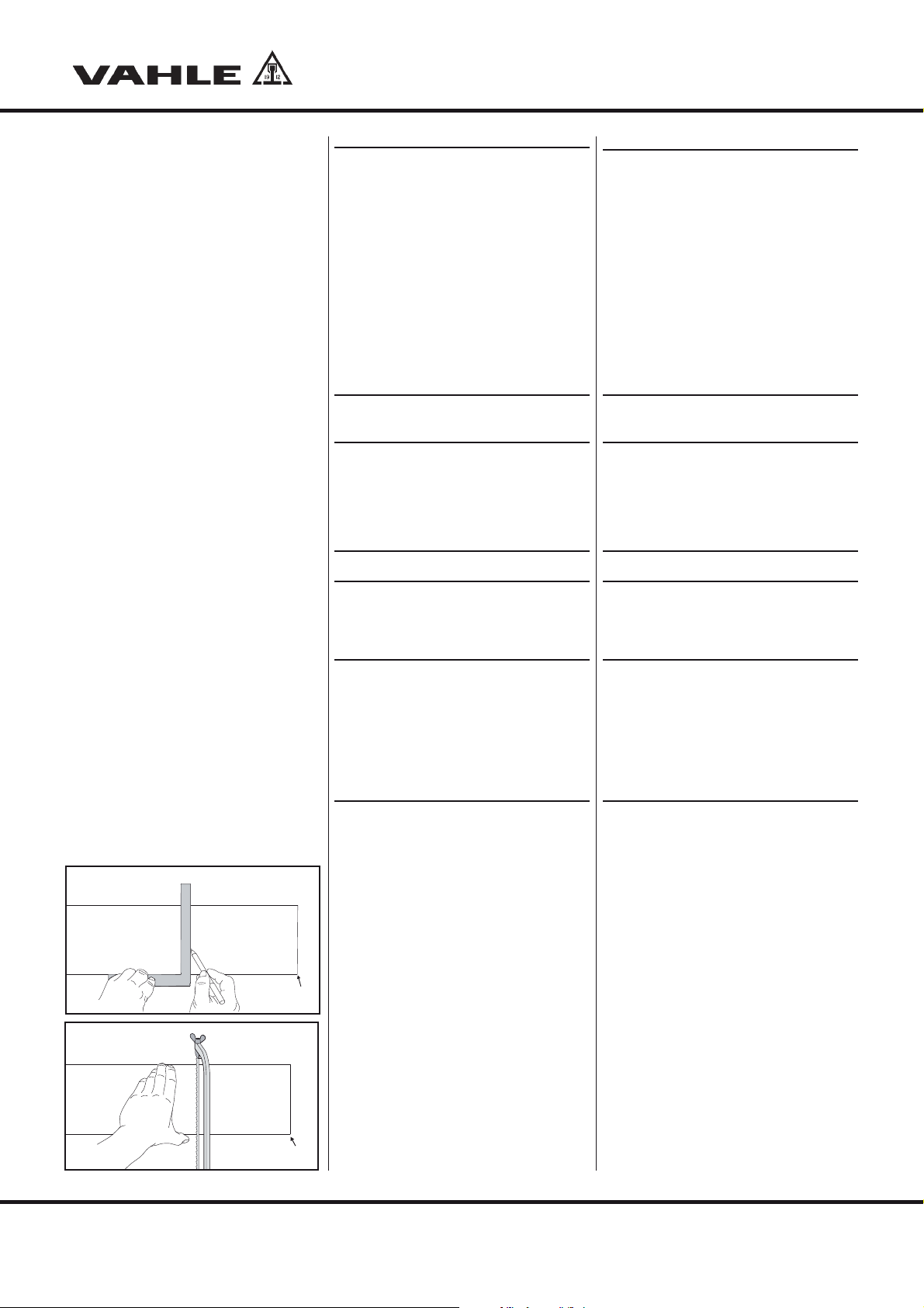
Richten Sie die Verbinderkappe mit
dem Montagehilfswerkzeug, welches
die Kappe einwandfrei über den Stoß
setzt, optimal aus (G8).
HAchten Sie bitte auf einwand-
freies Einfädeln der Steck-
verbinder.
Align the joint cap with an angiliary
tool that places the cap perfectly over
the joint (G8).
HEnsure that the connectors are
mating in correctly.
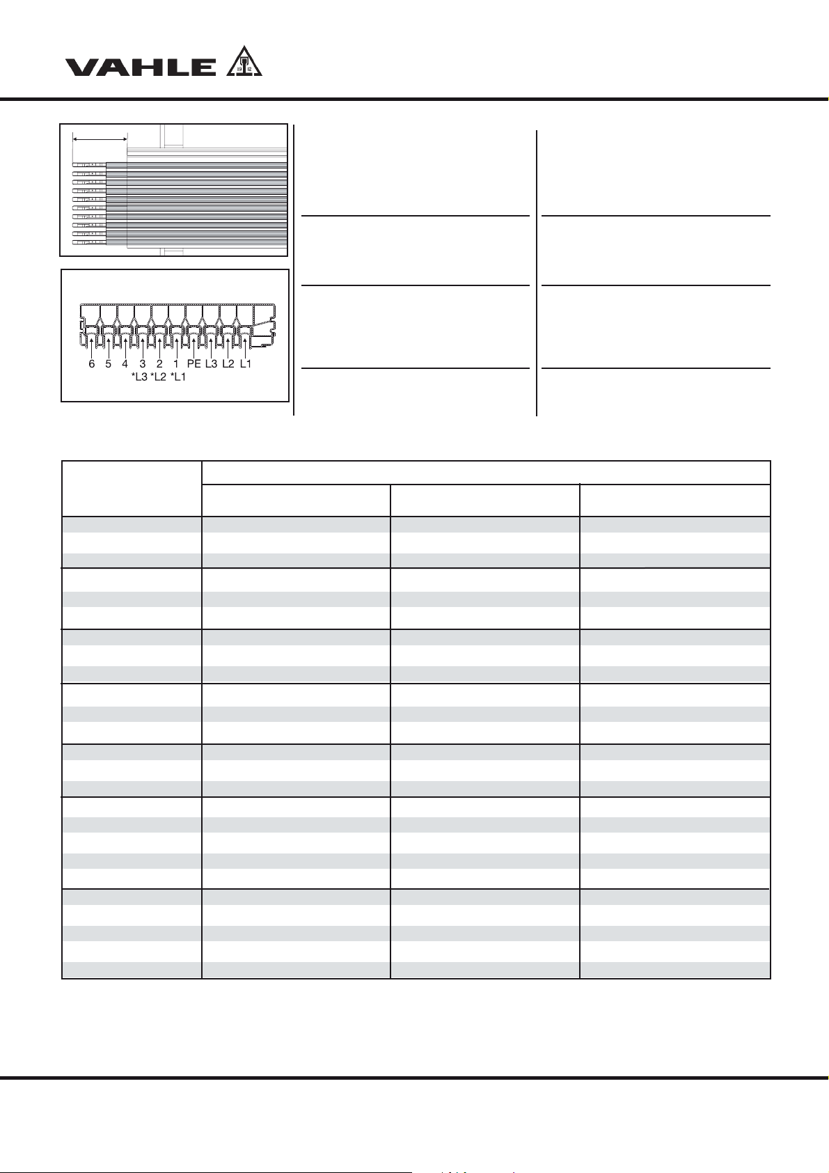
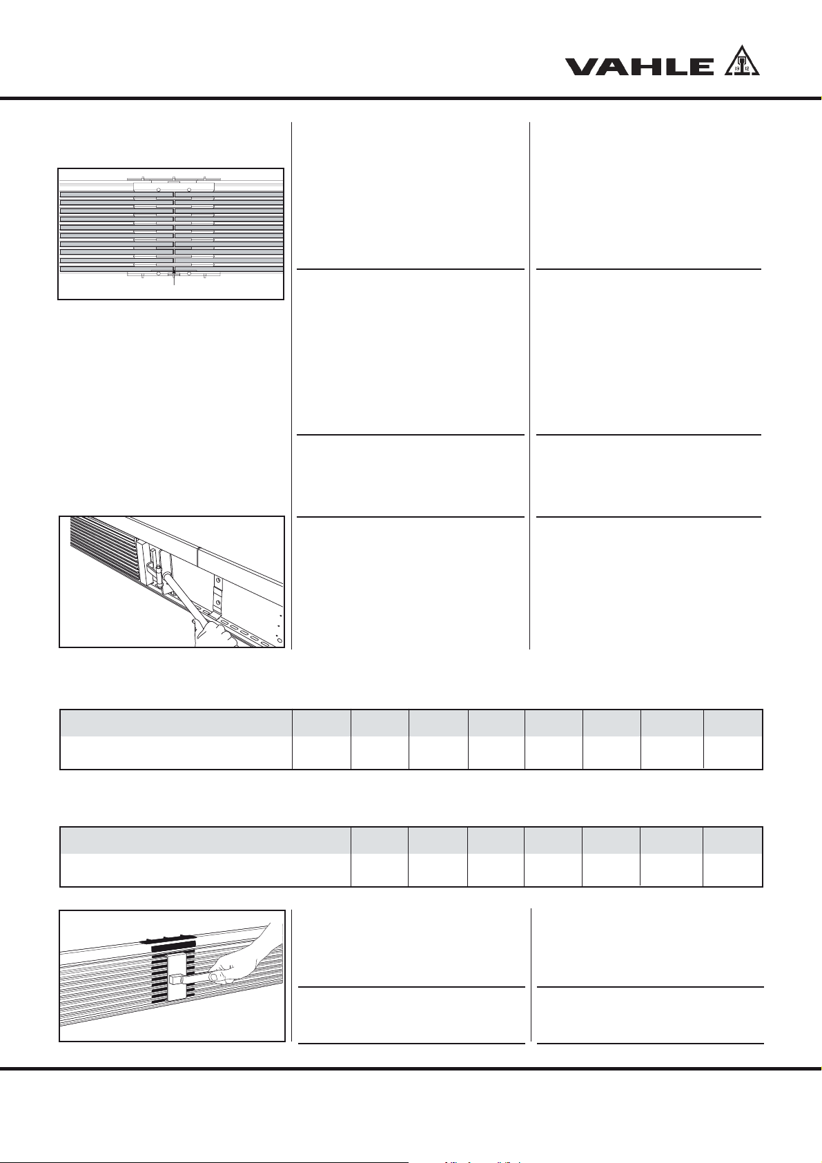
Tabelle T2 Einsatz Standard 6 m Teilstücke
Table T2 Use of standard 6 m conductor sections
Montagetemperatur in °C -30 -20 -10 0 10 20 30
Mounting temperature in °C
Luftspalt „A“ in mm standard 4 m 4,2 3,5 2,8 2,1 1,4 0,7 0
Air gap ,,A“ in mm standard 4 m
Tabelle T2 Tielkühllager: Einsatz 4 m Teilstücke
Table T2 cold storage: Use of 4 m conductor sections
Montagetemperatur in °C -30 -20 -10 0 10 20 30 40
Mounting temperature in °C
Luftspalt „A“ in mm standard 6 m --543210
Air gap ,,A“ in mm standard 6 m
G8

Montageanleitung •Mounting instructions
10
VKS 10
HDie Einstellmaße nach Tabelle
T2 müssen nur dann genau
eingehalten werden, wenn der
für die Schleifleitung max.
Temperaturbereich (-10 °C bis
+ 40 °C) zu erwarten ist.
Bei geringeren Temperaturdif-
ferenzen (욼t < 20 °C) kann zur
Vereinfachung der Montage
die Schleifleitung so zusam-
mengeschoben werden, dass
ein geschlossener Kupferstoß
entsteht. Der Luftspalt an den
Isoliergehäusen stellt sich
dabei selbständig ein.
Montieren Sie die nachfolgenden Teil-
stücke auf die gleiche Art.
HDer lichte Abstand der Aufhän-
geklammern zu den Verbinder-
kappen, Einspeisungen usw.
muss mindestens 50 mm betra-
gen, um die Ausdehnung nicht
zu behindern.
5.4 Unterlängen
Wir fertigen die Unterlängen nach Ihren An-
gaben im Werk. Falls Unterlängen auf der
Baustelle noch angepasst werden müssen,
bearbeiten Sie die Schleifleitung wie folgt.
HDie linke Seite der Stromschie-
nen ist werkseitig aufgeweitet,
um ein Verschieben im Kunst-
stoffgehäuse zu verhindern.
Kürzen Sie deshalb immer nur
die rechte Seite. Die Ziffer 1in
G9-G10 kennzeichnet die
WCS-Aufnahme.
Schieben Sie die Stromschienen an
der rechten Seite mit einem Holzbrett
bis zum bündigen Anschlag am
Isoliergehäuse ein.
Zeichnen Sie die neue Teilstücklänge
rechtwinklig ein (G9).
Sägen Sie die Schleifleitung an der
Markierung ab (G10).
HThe adjustment dimensions
according to Table T2 must only
be observed precisely if the
max.
temperature range (-10 °C
to +
40 °C) stipulated for the conduc-
tor rail is to be expected.
In the case of lower temperature
differences (욼t < 20 °C), in order
to simplify installation, the cop-
per conductors can be pushed
together such that a closed cop-
per joint is created. The air gap
on the insulating housings ad-
justs itself automatically.
The end caps terminate the conductor
rail and prevent accidental contact.
HThe distance between hangers
and the connector caps, feed
terminals etc. must be at least
50 mm so as not to obstruct
expansion.
5.4 Short-lengths
We manufacture short-lengths according
to customer`s specifications in our factory.
If short-lengths still need to be adapted
on site, proceed as follows.
HThe copper conductors are
anchored at the left side of the
PVC housing. Therefore always
make cut at the right hand side
of a section. The numeral 1in
G9-G10 designates the WCS
mounting.
Use a wooden block to push the cop-
per conductors on the right-hand
side until they are flush with the PVC
housing.
Mark the section to be cut perpendi-
cular (right angle) (G9).
Use a fine tooth saw to cut the con-
ductor rail (G10).
1
G10
1
G9

VKS 10
11
Schieben Sie nun die Stromschiene
soweit zurück, bis beidseitig der glei-
che Überstand ,,B“ erreicht ist (G11).
Entgraten Sie die gekürzten Strom-
schienenenden, sowie das Isolierprofil.
5.5 Biegen der Schleifleitung
Die Schleifleitungen werden grundsätz-
lich nur werkseitig gebogen.
Der Mindestradius beträgt:
Innenradius R = 1000 mm
Aussenbögen R = 1500 mm
5.6 Endkappen
Endkappen bilden den berührungsge-
schützten Abschluss der Schleifleitung.
Stecken Sie zuerst die Kriechwegver-
längerung auf die Enden (G12).
Schieben Sie die Endkappen auf die
Schleifleitungsenden auf (G13).
HDie Verschraubung der Endkap-
pen erfolgt von der Stromschie-
nenseite durch die vorgelochten
Bohrungen. Beachten Sie die
Kennzeichnungen für rechts (R)
und links (L) auf der Endkappe.
Verschrauben Sie die Endkappen mit der
Schleifleitung (G14). Die Schrauben sind
in der Verpackungseinheit enthalten.
HDer Überhang zur ersten bzw.
letzten Aufhängung darf max.
300 mm betragen (G15).
Now push back the copper conduc-
tor until it extends equally on both
sides of the PVC housing ,,B’’ (G11).
Deburr the shortened copper con-
ductor ends and the isolating-profile.
5.5 Bending of the powerail
The curves are generally bent in our
factory.
The minimum bending radius is:
Inner curves R = 1000 mm
Outer curves R = 1500 mm
5.6 End caps
The end caps terminate the conductor
rail and prevent accidental contact.
First place the creepage path exten-
sion onto the ends (G12).
Push the end caps on the conductor
rail ends (G13).
HFixing of the end caps from the
conductor side using the
prepared borings. Consider
mark of the right (R) and left (L)
hand version of the end cap.
Screw the end caps to the powerail
(G14). The screws are included in the
packing unit.
HThe extension beyond the first
or last hanger may not exceed
300 mm (G15).
Montageanleitung •Mounting instructions
G12
BB
G11
G14
G13
max. 300 mm
G15

VKS 10
12
Montageanleitung •Mounting instructions
G16
6 Feed terminals
HMount line feeds preferably on
a 1 m section.
If at all possible, place the feed termi-
nal in the proximity of the supply cable.
Cut support profile by 600 mm to
connect the line feed. An additioanl auxil-
iary support is required if the distance
between rack supports exceeds 1,5 m
(see layout plan).
6.1 Line feed VLS
Remove the cover cap from the
installed line feed.
Strip and cut the indicidual wires in the
area of the feed.
Strip off the connecting cable ac-
cording to requirement to single
cores. The additional conductor pro-
tection is still warranted through the
hollow profile.
Install cable lugs to the single wires.
Insert connection bolts with spacers
into prepared conductor rail.
Bolt the cable lugs, using the hexago-
nal bolts (M 6), spring washers and
hexagon nuts onto the terminal studs
(G16).
HTorque M 6 = 7 Nm
Cable entry left is standard, ca-
ble entry right is also possible.
Place the cover cap over line feed
terminals and watch wire routing
(G17).
6 Einspeisungen
HDie Streckeneinspeisungen sind
vorzugsweise auf einem 1 m
Schleifleitungsstück montiert.
Setzen Sie die Einspeisung möglichst
in die Nähe der Zuleitung.
Um an die Einspeisung zu gelangen wird
das HRL-Tragprofil in diesem Bereich um
600 mm ausgenommen. Falls der
Steher-,Stützabstand > 1,5 m beträgt,
muss zusätzlich eine Hilfsstütze gesetzt
werden (siehe Verlegungsplan).
6.1 Streckeneinspeisung VLS
Demontieren Sie die Abdeckkappe an
der montierten Streckeneinspeisung.
Enfernen Sie die äußere Isolation der
Anschlussleitung im Bereich der
Einspeisung.
Setzen Sie die Anschlussleitung nach
Erfordernis auf Einzeladerlänge ab.
Der zusätzliche Leiterschutz ist
weiterhin durch das Hohlkammerpro-
fil gewährleistet.
Bringen Sie die Kabelschuhe an den
Einzeladern an.
Setzen Sie die Anschlussbolzen und
Distanzstücke in die dafür vorbereite-
ten Bohrungen der Schleifleitung.
Schrauben Sie die Kabelschuhe mit
den Sechskantschrauben (M 6),
Federringen und Sechskantmuttern
an die Anschlussbolzen (G16).
HAnzugsmoment M 6 = 7 Nm.
Kabelausgang standardmäßig
links; rechts auch möglich.
Setzen Sie die Abdeckkappe auf die
Schleifleitung und achten auf den Ka-
beldurchgang (G17).
click
click
G17

VKS 10
13
Montageanleitung •Mounting instructions
Cable entry is either side (left or right)
from the cable connection (G18).
The connecting cables for the line feed
VLS can be supplied as well preassem-
bled (preferebly neoprene cables
HO7RN-F / H07V - K).
6.2Line feed VNS
Open the cover of the preassembled
line feed.
Strip and cut the individual wires as
required.
Install cable lugs to the single wires
and put connecting cable through the
cable gland.
Bold the cable lugs, using the hexa-
gonal bolts (M10; M5), spring was-
hers and hexagon nuts into the termi-
nal studs (G19).
HTorque in accordance to
DIN VDE 0220 T2
M 10 = 44 Nm
M 5 = 5 Nm.
Tighten the cable gland to guarantee
a sealing of the cable (G20).
Place cover on to the terminal box
and close it (G21).
6.3 End feed VEKS 10
The end feed consists of a terminal box
and the feeding VLS (please refer to line
feed VLS).
Push the end feed either to the left or
right hand side on a powerail line feed
section VLS (G22) and fix the box
with two screws (G23). The screws
are included in the packing unit.
Der Kabelausgang erfolgt seitlich
(links oder rechts) vom Kabelan-
schluss (G18).
Die Anschlussleitungen für die
VLS-Streckeneinspeisungen können
auch vormontiert geliefert werden
(vorzugsweise Gummischlauchleitung
HO7RN-F / H07V - K).
6.2 Streckeneinspeisung VNS
Öffnen Sie den Deckel an der mon-
tierten Streckeneinspeisung.
Setzen Sie die Anschlussleitung nach
Erfordernis auf Einzeladerlänge ab.
Bringen Sie die Kabelschuhe an den
Einzeladern an und führen Sie die
Anschlussleitung durch die Kabelver-
schraubung.
Schrauben Sie die Kabelschuhe mit
den Sechskantschrauben (M10; M5),
Fächerscheiben und Sechskantmut-
tern an die Anschlussfahnen (G19).
HAnzugsmomente in Anlehnung
an die DIN VDE 0220 T2
M 10 = 44 Nm
M 5 = 5 Nm.
Ziehen Sie die Kabelverschraubung
soweit an, bis eine Abdichtung zur
Anschlussleitung erfolgt (G20).
Setzen Sie den Deckel auf und ver-
schließen Sie den Anschlusskasten
(G21).
6.3 Kopfeinspeisung VEKS 10
Die Kopfeinspeisung besteht aus einem
Anschlusskasten und der VLS-Einspei-
sung (siehe VLS-Einspeisung).
Schieben Sie die Kopfeinspeisung
nach Wahl links oder rechts auf ein
Schleifleitungsende der VLS-Strecken–
einspeisung (G22) und fixieren Sie den
Kasten mit zwei Schrauben (G23). Die
Schrauben sind in der Verpackungsein-
heit enthalten.
G19
G20
765L3L2 L1
G18
G21
G22
G23

VKS 10
14
Montageanleitung •Mounting instructions
1
2
3
G26
G25
G24
Push the cable trough the isolating
profile and cable gland.
HConsider mark of the right (R)
and left (L) hand version of the
end cap.
Tighten the cable gland to guarantee
a sealing of the cable (G24).
Place cover into the terminal box and
Place cover into the feeding (G26).
7 Current collector
SRisk of damage trough re-
versal of phase!
Observe the correct pole allo-
cation for the current collector!
7.1 Current collector bracket
For the current collector, the mounting
bracket must be designed in parallel to the
longitudinal direction of the conductor rail as
well as at right angles to the contact surface.
Mount the current collectors at the
intended position.
HThe installation height "H" (S1)
of the current collectors, is
shown in table T3.
Push the current collector into
the intended position.
Align the current collector to the cen-
ter of the copper conductor.
Ziehen Sie dann die Kabel durch das
Isolierprofil und die Kabelverschrau-
bung.
HBeachten Sie die Kennzeich-
nung für rechts (R) und links (L).
Ziehen Sie die Kabelverschraubung
soweit an, bis eine Abdichtung zur
Anschlussleitung erfolgt (G24).
Setzen Sie den Deckel auf und ver-
schließen Sie den Anschlusskasten
(G25).
Setzen Sie die Abdeckkappe auf die
Einspeisung (G26).
7 Stromabnehmer
SBeschädigungsgefahr durch
Verpolung!
Achten Sie auf die richtige Pol-
zuordnung des Stomabneh-
mers.
7.1 Halter für Stromabnehmer
Für die Stromabnehmer muss die Befe-
stigungsfläche parallel zur Längsrichtung
der Schleifleitung, sowie rechtwinklig zur
Schleiffläche ausgeführt sein.
Befestigen Sie die Stromabnehmer in
der vorgesehenen Position.
HDie Einbauhöhe „H“ (S1) ent-
nehmen Sie bitte der Tabelle T3.
Schieben Sie den Stromabnehmer in
die vorgesehene Position.
Richten Sie den Stromabnehmer auf
Phasenmitte aus.

VKS 10
15
Montageanleitung •Mounting instructions
HFür den Schutzleiter-Stromab-
nehmer ist der Mitnehmer ent-
sprechend ausgefräst (S1).
Befestigen Sie den Stromabnehmer
mit der Befestigungsschelle.
HDie für den Betrieb zulässigen
Toleranzen ,,A“ für Hub (S2 + S4)
und Auslenkung (S3 + S5) gelten
für Stromabnehmer und Schleif-
leitung im Zusammenhang. Sie
sollen die Differenzen ausglei-
chen, die durch Führungsunge-
nauigkeiten des Fahrzeugs und
möglichen Montageversatz der
Schleifleitung entstehen.
Verlegen Sie den freihängenden Teil
der Anschlussleitung mit einem Mini-
malbiegeradius von 10 x Leitungs-
durchmesser.
Befestigen Sie die Stromabnehmer an
den dazu vorgesehenen Mitnahme-
punkten der beweglichen Verbraucher.
SBeschädigungsgefahr für die
Stomabnehmer!
Die Anschlussleitungen dürfen
die Beweglichkeit der Strom-
abnehmer nicht behindern und
müssen hochflexibel sein.
HThe carrier is suitably milled for
the ground current collector
(S1).
Install the current collector by using
the collector bracket.
HThe permissible tolerances
"A" for lift (S2 + S4) and swivel
(S3 + S5) apply commonly for
collector and conductor rail.
They are intended to compen-
sate for differences resulting
from guiding inaccuracy of the
vehicle and possible misalign-
ment installation of the con-
ductor rail.
Install the suspended part of the con-
nection cable so that its bending ra-
dius will always be larger than 10
times the cable diameter.
Mount the current collectors at the by
the customer designated location.
SRisk of damage to the
current collector!
The connection cable must not
hinder collector movement
and flexibility in any way and
have to be high flexible.
Tabelle T3/ Table T3
KST 30 bis KST 63 85 ±20
KSTU 30 bis KSTU 63 85 ±20
KESR 32-55 S-6-14 bis10-14(1) 88 ±15
KESR 32-55 F-6-14 bis10-14(1) 88 ±15
KESL 32-63 S-6-14 bis 10-14(1) 105 ±30
KESL 32-55 F-6-14 bis 10-14(1) 105 ±30
KESR 63 S-6-14 HS bis 10-14 HS KBL + KBR(1) (2) 133 ±15
KESL 63 S-6-14 HS bis 10-14 HS KBL + KBR(1) (2) 150 ±30
Stromabnehmertypen
Collector types
Einbauhöhe / Installation height
H
Hub-und seitliche Auslenkung (A)
Horizontal and vertical tolerances (A)
A
A
S3
A
(3)
KESL
S2
A
(3)
KESR
S4
AA
S5
Auslenkung
Swivel
Auslenkung
Swivel
Hub
Lift
Hub
Lift
Einsatz im Tiefkühllager (mit Sonderanschlussleitung) auf Anfrage / Operation in deep freeze warehouse (with special connecting cable) on request
(1) Einsatz mit Flachsteckeranschluss und/oder Schraubanschluss / Use with flat plug and/or bolted connection
(2) Ausführung mit Adapterblech und Klemmblock / Design with adapter plate and clamping box
(3) Anzugsmoment 1,2 Nm (Schraubanschluss) / Fastening Torque 1,2 Nm (Bolted connection)
HS1
KST, KSTU

VKS 10
16
Montageanleitung •Mounting instructions
7.2 Stromanschluss herstellen
BVerletzungsgefahr durch
Stromschlag!
Bevor Sie die elektrische Ver-
bindung herstellen, müssen
Sie die Anlage spannungslos
schalten!
Schliessen Sie die Einspeisung an das
Stromnetz an (siehe Kapitel Einspeisungen).
Verdrahten Sie die Stromabnehmer
mit den Verbrauchern.
SBeschädigungsgefahr durch
Verpolung!
Achten Sie auf die richtige
Polzuordnung.
HSchalter, Sicherungen und Ka-
bel zur Verdrahtung sind kun-
denseitig bereitzustellen und
zu montieren.
8 Sonderkomponenten
montieren
8.1 Einführungstrichter
Einführungstrichter werden mit einem
Schleifleitungsstück ausgeführt. Der
Einführungstrichter ist links sowie rechts
an entsprechend vorbereiteten VKS-Teil-
stücken anbaubar.
HBeschädigungsgefahr für
die Stromabnehmer und Ein-
führungstrichter!
Im Einfahrbereich der Trichter
gelten für die Stromabnehmer
eingeschränkte Toleranzen für
Hub und Auslenkung von max.
15 mm in allen Richtungen.
Die Einfahrgeschwindigkeit
beträgt max. 100 m/min.
Montieren Sie die Stütze nach Verle-
gungsplan.
Befestigen Sie das Halteblech an der
Stütze (G27).
Befestigen Sie die HRL-Aufhängung
an dem Halteblech (G28).
7.2 Power connection
BRisk of injury by electric
shock!
Before you make any electric
connection, make absolutely cer-
tain that the main feed has been
disconnected and locked out.
Connect the feed terminal to the main
power supply (see chapter on feed termi-
nals).
Wire the current collectors to the
equipment.
SRisk of damage due to incor-
rect phase orientation!
Ensure that the phases are as-
signed correctly.
HSwitches, fuses, and cables
for wiring must be provided
and installed by the customer
8 Mounting special
components
8.1 Transfer funnels
Transfer funnels are supplied on a
powerail section. The funnel can be
mounted on the left or right hand side of
preassembled VKS-powerail sections.
HRisk of damage of collectors
and transfer funnels!
Restricted tolerances are valid
for the collectors in the area of
the funnels, i.e.15 mm max.
horizontal and vertical move-
ment in each direction. The
max. speed is limited to.
100 m/min.
Install the support as per the layout
drawing.
Fasten the support plate to the support
(G27).
Fasten the hanger to the support
plate (G28).
G28
G27

VKS 10
17
Montageanleitung •Mounting instructions
Schrauben Sie das HRL-Tragprofil an
die HRL-Aufhängung (G29).
Befestigen Sie die Schleifleitung in
dem HRL-Tragprofil (siehe Kapitel
„Schleifleitung aufhängen“)
Setzen Sie die drei Aufhängeklam-
mern in die Trichterbohrungen ein (1)
und schieben den Trichter auf das
Schleifleitungsstück auf (G30).
Befestigen Sie den Einführungstrich-
ter mit den VKS-Aufhängeklammern
an dem Halteblech (G31).
Sichern Sie die Aufhängeklammern
durch die Festpunktschrauben
(siehe G3).
Richten Sie die Trichtereinheit an der
Hilfsstütze genau aus und befestigen
Sie diese (G32).
8.2 Doppel-Streckeneinführung
Die Doppel-Streckeneinführung besteht
aus einer oberen und einer unteren Ein-
führungsleiste, welche im Kopfgang an ei-
nem Schleifleitungs/Tragprofilteilstück an-
geschraubt wird (G33).
Richten Sie die Doppel-Streckenein-
führung bei der Montage mit dem
Stromabnehmer am Regalbediengerät
aus.
Kleben Sie die PVC Leisten im Bereich
der Streckeneinführungen ein.
aVKS 10 Aufhängungen und
VTP10 Aufhängungen/Verbin-
der nicht im Bereich der Strek-
keneinführung montieren.
Genaue Einbausituationen ent-
nehmen sie dem zugehörigen
Verlegungsplan.
Bolt the support profile to the hanger
(G29).
Fasten the conductor rail section to
the support hanger (see chapter „In-
stallation of the VKS conductor rail“)
Insert the three hanger clamps into
the funnel borings (1) and push the
funnel onto the conductor section
(G30).
Fasten the funnel with the VKS hang-
er clamps to the support plate (G31).
Secure the hanger clamps with fix-
point screws (see G3).
Align the funnel with the support and
fasten it there to (G32).
8.2 Tangential entry funnel
The tangential entry funel consists of an
upper and lower entry frame which is
mounted at the cross aisle on the con-
ductor rail / support profile (G33).
Align the tangential entry funnel
during installation with the current
collector at the AS/RS.
Glue the PVC strips in the area of the
entry funnel.
aDo not mount the VKS 10 han-
gers and the VTP 10
hangers/connectors near the
entry funnel. Detailed installati-
on arrangements could be seen
on the corresponding layout
drawing.
1
G29
G30
G31
G32
G33

VKS 10
18
Montageanleitung •Mounting instructions
HEmpfehlenswert ist es eine
Referenzgasse mit einem Refe-
renzgerät zu erzeugen. Danach
müssen mit diesem Referenzge-
rät alle Gassen angefahren
werden. Nun müssen alle
Stromabnehmerpakete nach
dem Referenzgerät ausgerichtet
werden. Hierdurch wird gewähr-
leistet, dass alle Regalbedienge-
räte alle Gassen anfahren
können.
8.3 Schienentrennungen
Mit den Schienentrennungen wird die
Schleifleitung elektrisch getrennt. Der Ein-
bau im VKS-Teilstück erfolgt werkseitig.
9 Wegmess-Systeme
9.1 APOS
(siehe separate Montageanleitung)
9.2 WCS-Laminat-Codeschiene
Stecken Sie das Kunststoff-Laminat-
band in die Nut des Isolierprofils.
Verbinden Sie das Isolierprofil mit
dem Kunststoff-Laminatband anhand
der Befestigungsklammern aus
Federstahl (G34).
HAchten Sie darauf das die Klam-
mer zuerst in die Nut (1) greift.
Setzen Sie das Laminatband an je-
dem Schleifleitungsteilstück mittig
mit einer Schraube fest.
Der Befestigungsabstand beträgt 200 mm
(Langloch 6,6 x 30 mm im Laminat alle
200 mm).
Erdung der Codeschiene
Mind. alle 30 m ist die Laminatschiene
mit dem Anlagenpotenzial zu verbinden
(z.B. Vahle Tragprofil).
9.3 Barcodeband
Neben dem Wegmesssystem kann auch
das selbstklebende Barcodeband (BCB)
auf den Steg aufgeklebt werden (G35).
Überprüfen Sie den Untergrund:
Er muss glatt, fett und staubfrei sowie
trocken sein.
HRecommended is to create a
reference aisle with a reference
device. Afterwards all aisles
have to be short passed with
this reference device. Then all
compact current collector sets
have to be aligned to this
reference device. Through this is
garanteed that all AS/RS
devices could travel in all aisles.
8.3 Conductor isolators
The conductors may be electrically sepa-
rated by installing isolators. The isolators
are installed at the factory.
9 Positioning systems
9.1 APOS
(see separate mounting instruction)
9.2 WCS laminate code rail
Push the laminate code rail into the
groove of the isolating profile.
Connect the isolating-profile with the
laminate code rail through the steel-
clamps (G34).
HMake sure the clamp sits prop-
erly in the groove (1).
Anchor the laminate code rail with a
screw at each conductor section.
The support distance is 200 mm (the code
rail has slotted holes 6,6 x 30 mm in
200 mm centres).
Earthing of the code rail
Minimum every 30 m the laminate code
rail has to be connected with the system
potential. (e.g. VAHLE support rail.
9.3 Barcode band
Instead of the laminate code rail the adhe-
sive barcode stripe can be used as well
(G35).
Please check the underground:
It must be plain, free of grease and dust
and dry.
G34
(1)
G35
BCB

VKS 10
19
Montageanleitung •Mounting instructions
10 Montageabschluss
Nach Beendigung der Montage ist die
Anlage auf Funktionsfähigkeit zu prüfen.
aNach Montage des HRL-Trag-
profils ist für eine ausreichende
Erdung Sorge zu tragen.
11 Inbetriebnahme
Führen Sie nach ordnungsgemäßer Mon-
tage eine Probefahrt durch. Hierbei müs-
sen Sie folgende Punkte beachten:
- erste Fahrt mit geringer Geschwindigkeit,
- Schleifkohlen müssen ohne Vibration in
der Stromschiene laufen,
- Funkenbildung an der Schleifkohle darf
nicht auftreten (deutet auf verschmutz-
te oder oxidierte Schleiffläche hin ->
Schleiffläche säubern).
12 Wartung
BVor Beginn der Wartungsarbeit
beachten Sie bitte die Sicher-
heitshinweise auf der Seite 3.
12.1 Schleifleitung
- Geringe Wartung bei normalen Um-
welteinflüssen und Beanspruchungen.
- Regelmäßige Überprüfung auf Fremd-
beschädigung.
- Optische Kontrolle alle 4 Wochen, da-
bei auf Ausdehnung der Stromschienen
und Brandstellen achten.
- Schleifkohlenstaub, besonders an
Trennstellen entfernen.
12.2 Stromabnehmer
Die Stromabnehmer müssen alle 2 Mo-
nate bzw. nach betrieblichen Erfordernis-
sen kontrolliert werden.
a) Mechanische Kontrolle:
Beweglichkeit der Gelenke, Lager und
Drehbolzen kontrollieren. Untersuchung
auf mechanische Schäden.
b) Elektrische Kontrolle:
Abrieb der Schleifkohlen, festen Sitz aller
Kontaktschrauben und Kabelbefestigung
überprüfen.
Schleifkohlen sind so rechtzeitig zu
ersetzen, dass die Fassungen der
Schleifkohlen nicht die äußeren Kanten
der Verbinderkappen berühren.
Für Schleifkohlen bitte die Resthöhe
beachten.
10 Installation completion
On completion of the installation the
system must be tested for functionality.
aAfter installation of the support
profiles please make sure that
the profile is grounded in a
adequate size.
11 Commissioning
Conduct a test run after the installation
has been completed. The following
points must be observed here:
- Make initial run at low speed,
- The carbon brushes should run in the
conductor rail without vibration,
- There should not be any sparking at the car-
bon brush (indicates that the conductor sur-
faces are dirty, oxidized or have burrs; clean
contact surface and/or remove burrs).
12 Maintenance
BBefore starting any mainte-
nance work, comply with the
safety instructions on page 3.
12.1 Conductor rail
-Little maintenance is required at normal
environment and operating conditions.
- Regular inspection for any external
damage.
- Visual inspection every four weeks;
note any expansions of the conductors
and burns.
- Remove carbon brush dust, particularly
from isolating sections.
12.2 Current collector
The current collectors must be checked
every two months or in accordance with
operational requirements.
a) Mechanical check:
Check the freedom of movement of the
articulated joints, bearings and pivots.
Examine for mechanical damage
b) Electrical check:
Check for abrasion of the carbon brush-
es as well as firm sealing of all contact
screws and cable connections.
Carbon brushes must be replaced suffi-
ciently early so that the holders of the
carbon brushes will not contact the out-
side edges of the joint splice caps.
For carbons please note the indicated
wear height.

VKS 10
20
Montageanleitung •Mounting instructions
c) Kontaktprüfung:
Schleifkohle mittels Federwaage aus der
Stromschiene herausziehen. Die Kon-
taktkraft soll bei ca. 5 N pro Schleifkohle
bei der Baureihe KST 30- KST 63 liegen,
beim KESR 3,5 N.
Beim KESL beträgt die Kontaktkraft
ca. 7N.
d) Anzugsmoment:
Das Anzugsmoment beträgt beim
KESR / KESL Stromabnehmer 1,2 Nm.
c) Contact pressure testing:
Pull the carbon brush out of the conduc-
tor rail with a spring scale. The contact
force should be 5 N per carbon brush for the
series KST 30- KST 63, for KESR 3,5 N
With the KESL the contact power is
approx. 7N.
d) Tightening torque:
The tightening torque amounts with the
KESR / KESL collector to 1,2 Nm.
RH mm
KST 30-KSTU 63 4,0
KESR 32-55 3,5
KESL 32-63 3,5
RH mm
KST 30-KSTU 63 4,0
KESR 32-55 3,5
KESL 32-63 3,5
Other manuals for VKS10
2
Table of contents