manuals.online logo
Brands
  1. Home
  2. •
  3. Brands
  4. •
  5. Vaillant
  6. •
  7. Boiler
  8. •
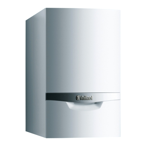
  9. Vaillant turboMAX plus 2 E Series User manual

Vaillant turboMAX plus 2 E Series User manual

For the installer
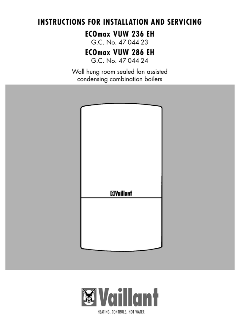
Flue installation instructions
Air flue duct for use with
turboMAX plus .../2 E
turboMAX pro .../2 E
thermoCOMPACT .../2 E
aquaPLUS
PART 1:
Standard Concentric Systems
Ø 60/100
PART 2:
Optional Concentric Systems
Ø 80/125
GB
2
CONTENTS: PART 1 CONCENTRIC 60/100
Requirements
Planning the air/flue duct layout
4
Alternative termination accessories available 5
Maximum flue lengths Ø 60/100 9
Flue restrictor rings 10
Preparation 11
Top outlet flue exiting to rear 11
Top outlet flue exiting to side 11
Preparation 14
Preparation of boiler for rear outlet air/flue duct 16
Installation of the horizontal
air/flue duct (top outlet)
Fitting air/flue duct extensions
Page
§
25
Fitting air/flue duct extensions
between two 90° elbows
26
Fitting air/flue duct extensions
between two 45° elbows
27
Installing the air/flue duct sliding
sleeve
28
Installation of the vertical
roof duct
Installation of the horizontal
air/flue duct (rear outlet)
Preparation 19
Top outlet flue exiting to rear 19
Top outlet flue exiting to side 19
Preparation 22
Pitched roof 23
Flat roof 23
Pitched and flat roof installation 23
Installation of the Se-Duct flue
3
CONTENTS: PART 2 CONCENTRIC 80/125
Planning the air/flue duct layout Termination accessories available 29
Maximum flue lengths Ø 80/125 32
Flue restrictor rings 33
35
Preparation 37
Side flue installations 37
Fitting the appliance flue outlet
adapter to the boiler
Fitting air/flue duct extensions
Page
45
Fitting air/flue duct extensions
between two 90° elbows
46
Fitting air/flue duct extensions
between two 45° elbows
47
Installing the air/flue duct sliding
sleeve
48
Installation of the vertical
roof duct
Installation of the horizontal
air/flue with extensions
Preparation 39
Fitting extensions 40
Connect the flue assembly to the adaptor 40
Installation of the horizontal
air/flue duct and terminal
accessory (80/125)
Preparation 41
Pitched roof 42
Flat roof 42
Pitched and flat roof installation 42
Connect the flue assembly to the adaptor 44
§
REQUIREMENTS
4
☞Vaillant turboMAX,
thermoCOMPACT and aquaPLUS
boilers are certified as heating
boilers with corresponding flue
systems according to EC Directive
90/396/EEC on gas-fired
devices. This installation manual is
covered by this certification and is
referred to in the design approval
test certificate.
☞These instructions should be read
in conjunction with the instructions
for installation and servicing
supplied with the boiler.
☞Ensure also that all legislation,
rules, regulations and directives
mentioned in the installation
instructions are observed.
☞The installation of the boiler and
its flue must be carried out by a
competent person who is
registered with CORGI (The
Council for Registered Gas
Installers).
☞The installation of the boiler and
flue must be in accordance with
the Gas Safety (Installation and
Use) Regulations 1998 and the
Building Regulations and
BS 5440 Part 1.
☞The requirements for flue
termination detailed in the boiler
installation instructions must be
observed.
☞Two types of flue system are
available for turboMAX,
thermoCOMPACT and aquaPLUS
boilers. The standard concentric
flue system (100 mm outside
diameter) and a larger diameter
concentric system (125 mm
outside diameter) which allows
longer air/flue duct lengths to be
achieved.
☞The air/flue duct operates at very
low temperatures therefore no
clearance is necessary between
the air duct and adjacent
services.
☞Ensure while installation work is
being carried out that no debris
such as swarf, filings or fragments
of mortar are allowed to remain
in the air/flue duct.
Air/flue duct (adjustable) offset (33 -56 mm)
Ø 60/100
5
PART 1 CONCENTRIC 60/100
PLANNING THE AIR/FLUE DUCT LAYOUT
Alternative termination
accessories available
Optional connection accessories Accy. No.
303 807 303 806
Air/flue duct extension
500 mm - Ø 60/100 303 801 x x
Air/flue duct extension
1000 mm - Ø 60/100 303 802 x x
Telescopic air/flue duct extension
500 - 800 mm - Ø 60/100 303 804 x x
2 x 45° Bends
Ø 60/100 303 809 x x
90° Elbow
Ø 60/100 303 808 x x
Flue support clips (Pack of 5), Ø 100 303 821 x x
Air/flue duct extension
1960 mm - Ø 60/100 303 803 x x
Air/flue duct 15° offset
Ø 60/100 303 820
Sliding sleeve Ø 60/100 303 816 x x
Adjustable roof tile 9076
Flat roof collar-piece 9056
x x
303 810
x
x
x
x
x
x
x
x
x
303 800
x
x
x
x
x
x
x
x
x
x
x
303 807 = Horizontal air/flue duct with 90° elbow and
terminal (750 mm)
303 806 = Telescopic horizontal air/flue duct with 90° elbow and
terminal (450 - 650 mm; turboMAX and thermoCOMPACT only)
303 817 = Rear outlet flue and terminal (for wall thicknesses
200 mm to 305 mm; turboMAX and thermoCOMPACT only)
303 810 = Se-duct flue accessory
303 800 = Vertical air/flue duct and terminal accessory
x303 819 x x x
4
36
4
36
4
36
6
PLANNING THE AIR/FLUE DUCT LAYOUT
Fig. 1.1: Extensions, Ø 60/100
Fig. 1.3: Elbow joints, Ø 60/100
90° Elbow, Ø 60/100
Accy. No.: 303 808
2 x 45° Bends, Ø 60/100
Accy. No.: 303 809
Fig. 1.2: Telescopic extension
Telescopic air/flue duct extension
500 – 800 mm Ø 60/100
Accy. No.: 303 804
Air/flue duct extension 500 mm,
Ø 60/100
Accy. No.: 303 801
Air/flue duct extension 1000 mm,
Ø 60/100
Accy. No.: 303 802
Air/flue duct extension 1960 mm,
Ø 60/100
Accy. No.: 303 803
GU_LAZ 70/0
LAS Euro B/S 015/0 Teleskop_Verlängerung
Air/flue duct 15° offset Ø 60/100
Accy. No.: 303 820
Air/flue duct (adjustable) offset pipe
Ø 60/100
Accy. No.: 303 819
33 - 56
Abb. 1.4: Adjustable offset pipe
LAS Euro B/S 070/0GB
135
145
PART 1 CONCENTRIC 60/100
PLANNING THE AIR/FLUE DUCT LAYOUT
7
Fig. 1.7: Tiles for pitched roofs
Adjustable roof tile
Accy. No.: 9076
GU_LAZ 41/0
Fig. 1.6: Sliding sleeve, Ø 60/100
Sliding sleeve, Ø 60/100
Accy. No.: 303 816
LAS Euro B/S 016/0
Fig. 1.5: Flue support clip, Ø 100
Flue support clips, Ø 100 (Pack of 5)
Accy. No.: 303 821
GU_LAZ 72/0
☞Use one clip per extension to
support the air/flue duct.
Fig. 1.8: Flat roof penetration collar
GU_LAZ 42/0
Flat roof penetration collar
Accy. No.: 9056
5.3 5.3 4.5 3.3 3.0
PLANNING THE AIR/FLUE DUCT LAYOUT
8
Horizontal flue
systems
303 807
303 806
303 810
Maximum flue lengths Ø 60/100
Maximum flue length
Maximum flue length
Fig. 1.9 Fig. 1.10
LAS Euro B/S 074/0
LAS Euro B/S 075/0
Vertical flue
systems
303 800
thermoCOMPACT thermoCOMPACT thermoCOMPACT thermoCOMPACT thermoCOMPACT
615/2 E 620/2 E 624/2 E 628/2 E 637 E
turboMAX pro 24/2 E turboMAX pro turboMAX plus
turboMAX plus 28/2 E 837 E
824/2 E turboMAX plus aquaPLUS
828/2 E
6.3 6.3 5.5 4.3 4.0
Max.
permitted
flue length
(L)
Max.
permitted
flue length
(L)
Maximum length of flue is reduced by 1.0 m for each additional 90° elbow.
Maximum length of flue is reduced by 0.5 m for each additional 45° elbow.
Maximum length of flue is reduced by 1.0 m for each additional 90° elbow.
Maximum length of flue is reduced by 0.5 m for each additional 45° elbow.
3
2
1
= B
= D
= A
= C
PART 1 CONCENTRIC 60/100
PLANNING THE AIR/FLUE DUCT LAYOUT
9
Fig. 1.11: Flue restrictor rings
Flue restrictor rings
The flue restrictor ring marked A, C
or D is packed with the boiler
connection accessories. The restrictor
ring should be fitted as shown in the
diagram according to the equivalent
flue length in the table.
The total equivalent flue length is the
total length of the flue (including the
terminal assembly for vertical flues),
plus the resistance of any bends or
elbows used.
-equivalent length of 90° elbow is
1 m
-equivalent length of 45° elbow is
0.5 m
•Push the restrictor (1) into the flue
connection of the appliance (3)
•Connect the flue/elbow (2) into
the flue connection of the
appliance (3).
Note:
thermoCOMPACT 615 boilers do not
require a seperate restrictor ring and
are supplied without the restrictor.
The required restriction is designed
into the flue connection piece for
these boilers.
thermoCOMPACT
615/2 E
thermoCOMPACT
620/2 E
thermoCOMPACT
624/2 E
turboMAX plus
824/2 E
turboMAX
pro 24/2 E
thermoCOMPACT
628/2 E
turboMAX plus
828/2 E
turboMAX pro
28/2 E
Use restrictor A ---
Use restrictor D ---
No flue restrictor ---
< 6.3 m
---
---
---
---
---
---
< 2.3 m
> 2.3 m
Use restrictor C --- --- < 5.5 m ---
Total equivalent flue length
(incl. terminal any bends / elbows used)
PLANNING THE AIR/FLUE DUCT LAYOUT
10
Fig. 1.12: Flue restrictor rings
Flue restrictor rings
The flue restrictor ring marked F0 and
F1 is packed with the boiler
connection accessories. The restrictor
ring should be fitted as shown in the
diagram according to the equivalent
flue length in the table.
The total equivalent flue length is the
total length of the flue (including the
terminal assembly for vertical flues),
plus the resistance of any bends or
elbows used.
-equivalent length of 90° elbow is
1 m
-equivalent length of 45° elbow is
0.5 m
•Push the restrictor (1) into the flue
connection of the appliance (3)
•Connect the flue/elbow (2) into
the flue connection of the
appliance (3).
aquaPLUS thermoCOMPACT
637 E
turboMAX plus
837 E
Use restrictor F0 ---
Use restrictor F2 ---
No flue restrictor ---
< 2.5 m
---
> 3.3 m
< 2.5 m
---
> 3.3 m
< 2.5 m
---
> 3.3 m
Use restrictor F1 --- 2.5 - 3.3 m 2.5 - 3.3 m 2.5 - 3.3 m
Total equivalent flue length
(incl. terminal any bends / elbows used)
11
Horizontal air/flue duct
Accy No.: 303 807 (Length 0.75 m)
Accy No.: 303 806 (telescopic,
0.45 – 0.65 m; turboMAX and
thermoCOMPACT only)
Contents of the accessory:
•Horizontal air/flue duct
•90° elbow
•2x 48 mm air duct clamps
(3x with telescopic accy.)
•Internal trim ring Ø 100
•External wall seal.
Fig. 2.1: Horizontal air/flue conduit
IMPORTANT:
The flue hole should be cut with a
slight fall to outside of 1° to prevent
rain water entering the flue.
Preparation
•Determine the installation site for
the boiler with reference to the
installation and servicing
instructions supplied with the
boiler.
•Ensure that all installation and
service clearances are available
and that the boiler flue can be
installed as detailed in these
instructions.
•Fix the paper template, supplied
with the boiler, to the wall
ensuring that the centreline of the
template is vertical using a
plumbline or spirit level.
Top outlet flue exiting to rear
•For installations where the air/flue
duct is to be installed directly to
the rear of the boiler, the
installation template details the
position of the flue exit hole for
horizontal top outlet installation.
Top outlet flue exiting to side
•For installations where the air/flue
duct is to be installed to the side,
the position of the flue exit hole
can be determined by carefully
levelling across the wall from the
centre line of the air/flue duct
hole marked on the template.
•The position of the flue exit hole
should allow the flue to be
installed with a slight downward
slope of about 1° (equivalent to
10 to 15 mm per metre of flue
duct). Calculate the required fall
according to the flue length and
mark the position of the flue exit
hole.
48
750
48
4
LAS Euro B/S 037/0
110
1°
A
5
6
6
3
Fig. 2.2
LAS Euro B/S 072/0GB
INSTALLATION OF THE HORIZONTAL AIR/FLUE DUCT (TOP OUTLET)
turboMAX/thermoCOMPACT:
A = 145 mm
aquaPLUS:
A = 310mm
PART 1 CONCENTRIC 60/100
12
INSTALLATION OF THE HORIZONTAL AIR/FLUE DUCT (TOP OUTLET)
•Once the position of the flue exit
hole has been determined, the
hole should be cut through the
wall using a core drill of 127 mm
diameter.
Note: If access can be gained to
the proposed flue exit point from
outside the dwelling, the hole can
be cut with a 107 mm core drill
and the flue external wall seal
fitted from outside the dwelling.
•Measure the distance from the
outside face of the wall to the
centre of the fan outlet on the
boiler.
This is dimension A.
•(Note: If using the top connection
spacer frame accessory with the
boilers with a rear exit, make an
additional 45 mm allowance for
the depth of the frame).
•Cut the air duct and flue duct to
the lengths shown in figure 2.4.
•All flue sockets should point
towards the terminal.
•When cutting the air and flue
ducts it is important to remove any
burrs with a file, this ensures easy
fitting of the ducts and prevents
any rough edges from damaging
the flue seals.
Care should be taken not to
scratch the white surface of the air
duct.
•If the installation requires the use
of air/flue duct extensions,
additional bends or elbows refer
to the sections on pages 25 – 27.
•If using the telescopic horizontal
air/flue duct and terminal accy.
303806 simply adjust the length
as shown in Fig 2.4. Secure the
air duct sections together by
drilling a 3 mm diameter hole
through the location hole in the
end of the outer air duct. (Ensure
that the drill does not pierce the
inner flue duct). Secure the air
ducts together using the screw
provided.
1
2
*
* = 145 mm (TURBOmax/THERMOcompact)
* = 310 mm (aquaPLUS)
Fig. 2.3
LAS Euro B/S 077/1
110
A
B
A
110
Fig. 2.4
LAS Euro B/S 078/0
A + 15 mm
4 mm
Fig. 2.5
LAS Euro B/S 076/0
Rear exit
Side exit
turboMAX: B = 145 mm
aquaPLUS: B = 310 mm
13
PART 1 CONCENTRIC 60/100
•Push the air/flue duct assembly
(1) including the flexible external
seal (2) through the wall until the
seal clears the outside face of the
wall and pull air/flue duct back
towards the boiler until the
external seal touches the outside
wall.
•Ensure that the air/flue duct (1) is
centred in the hole and the
terminal is correctly positioned
with the inlet grille at the bottom.
•Slide the internal trim ring (3) over
the air duct until it is flush with the
wall.
•At this stage it is necessary to
prepare and fit the boiler onto the
hanging bracket – refer to the
boiler installation instructions.
•Before installing the flue elbow
onto the boiler flue outlet select
and fit the correct restrictor ring
(page 10) into the bottom of the
boiler elbow.
•Fit the elbow to the boiler by
inserting the spigot of the flue
elbow into the flue socket on the
boiler and secure using the air
duct clamp provided.
•Pull the air/flue duct back through
the wall such that the flue duct
fully engages into the flue elbow
socket.
•Fit the air duct clamp ensuring
that it is positioned centrally.
•Drill two holes 3 mm Ø through
the air duct of both the elbow/flue
and elbow/boiler clamps at the
most convienient holes on the air
duct clamps. (Ensure that the drill
does not penetrate the inner flue
duct). Screw the clamps to the air
ducts of the flue assembly, the
elbow and boiler using the
screws supplied.
•Slide the internal trim ring back to
the wall, securing in position with
a small amount of sealant if
required.
110
1
2
3
1°
Fig. 2.6
LAS Euro B/S 001/0GB
INSTALLATION OF THE HORIZONTAL AIR/FLUE DUCT (TOP OUTLET)
14
INSTALLATION OF THE HORIZONTAL AIR/FLUE DUCT (REAR OUTLET)
(TURBOMAX AND THERMOCOMPACT ONLY)
Rear outlet flue accessory
Accy No: 303 817
Contents of the accessory
•Rear air/flue duct
•Flue securing collar Ø 100
including fixing screws and wall
plugs
•Air duct connection piece and
screws
•Flue cap
•Rubber bung
•Air pressure tube extension and
connecting nipple
Fig. 3.1: Horizontal wall duct
LAS Euro B/S 073/1GB
IMPORTANT:
The flue hole should be cut with a
slight fall to outside of 1° to prevent
rain water entering the flue.
Minimum top clearance for rear
installation is 100 mm.
IMPORTANT:
To install this accessory access must
be available to the proposed flue exit
point outside the dwelling.
Preparation
•Determine the installation site for
the boiler with reference to the
installation and servicing
instructions supplied with the
boiler.
•Ensure that all installation and
service clearances are available
and that the boiler flue can be
installed as detailed in these
instructions.
•Fix the paper template, supplied
with the boiler, to the wall
ensuring that the centreline of the
template is vertical using a
plumbline or spirit level.
•The installation template details
the position of the flue exit hole
for rear outlet installations.
Ensure that the correct flue exit
hole has been identified.
•Once the position of the flue exit
hole has been determined, the
hole should be cut through the
wall using a core drill of 107 mm
diameter.
•Measure the thickness of the wall
through which the flue will pass.
This is dimension C.
•(Note: If using the top connection
spacer frame accessory make an
additional 45 mm allowance for
the depth of the frame).
•Cut the air duct and flue duct to
the lengths shown in figure 3.2.
•When cutting the air and flue
ducts it is important to remove any
burrs with a file, this ensures easy
fitting of the ducts.
98
C
15 65
L 1 = C + 180 mm
Fig. 3.2
LAS Euro B/S 059/1GB
750
15
INSTALLATION OF THE HORIZONTAL AIR/FLUE DUCT (REAR OUTLET)
(TURBOMAX AND THERMOCOMPACT ONLY)
•Secure the boiler hanging bracket
(1) to the wall using the screws
provided (2).
•At this stage it is necessary to
prepare and fit the boiler onto the
hanging bracket – refer to the
boiler installation instructions.
3
402
171 174,5
12,5
1
1
2
Fig. 3.3
LAS Euro B/S 054/0GB
PART 1 CONCENTRIC 60/100
16
INSTALLATION OF THE HORIZONTAL AIR/FLUE DUCT (REAR OUTLET)
(TURBOMAX AND THERMOCOMPACT ONLY)
1
2
5
4
3
Fig. 3.4
LAS Euro B/S 55/0
11
12
8
6
7
10
9
13
Fig. 3.5
LAS Euro B/S 056/1
Preparation of boiler for
rear outlet air/flue duct
For thermoCOMPACT 615, 637 and
turboMAX plus 837:
•Remove boiler case as detailed in
the installation instructions
supplied with the boiler.
•Release the three clamps (1) and
remove the combustion chamber
cover (2).
•Loosen the screw (3) and remove
the flue gas connector (4) from the
fan.
•Remove the retaining spring (5).
•Pull the cables and two tubes (9,
10) from the fan assembly. Please
ensure that you note the respective
connection points for each tube.
•Remove the complete fan assembly
(11) from the boiler.
•Remove the rubber funnel (12) and
place to side.
•Seal the hole with the rubber bung
(13) provided.
INSTALLATION OF THE HORIZONTAL AIR/FLUE DUCT (REAR OUTLET)
(TURBOMAX AND THERMOCOMPACT ONLY)
17
1
39
9
8
11
a
b
c
d
12
13
2
10
LAS Euro B/S 55_2.eps
Preparation of boiler for
rear outlet air/flue duct
For thermoCOMPACT 620, 624, 628,
turboMAX pro 24, 28 and turboMAX
plus 824, 828:
•Remove boiler case as detailed in
the installation instructions
supplied with the boiler.
•Release the three clamps (1) and
remove the combustion chamber
cover (2).
•Remove the screw (3).
•Pull the two cables (8) and two
tubes (9) from the fan assembly.
Please ensure that you note the
respective connection points for
each tube.
•Remove the fan (10) from the
collector hood by pushing
downwards to unlock.
•Remove collector hood from the
boiler
•Remove the rubber funnel (12).
•Seal the hole with the rubber bung
(13) provided.
PART 1 CONCENTRIC 60/100
Fig. 3.6
18
INSTALLATION OF THE HORIZONTAL AIR/FLUE DUCT (REAR OUTLET)
3
1
2
Fig. 3.7
LAS Euro B/S 061/0GB
Fig. 3.8
LAS Euro B/S 060/0
•Remove the metal plate (1)
covering the rear flue outlet point
by pushing through the centre pins
of the plastic fasteners as shown in
the drawing. Now remove the
metal plate by pulling on the
foldedtag of the plate.
•Fit the air duct connection piece
(2) to the back of the boiler at the
rear flue outlet point with the four
screws provided.
•Push the flue cap (3) firmly into
position to seal the top flue outlet.
•From outside the dwelling locate
the flue securing collar centrally
over the flue exit hole, mark and
drill the three holes and insert the
wall plugs provided.
•Push the flue securing collar on to
the flue at the opposite end to the
terminal, ensure that the flue
securing collar is fitted with the
holes for securing the collar to the
air duct facing outside.
•Push the air/flue duct assembly
through the wall from outside the
dwelling.
•If the internal trim ring is to be
used, position it over the end of the
air duct from inside the dwelling.
•Engage the end of the air duct into
the air duct connection piece at
the rear of the boiler. Now from
outside the dwelling push the
entire air/flue duct in towards the
boiler such that the air duct
completely engages all the way
into the air duct connection on the
boiler. Ensure that the flue terminal
is correctly positioned with the
hood at the top and the air inlet at
the bottom.
Important:
•Fix the flue securing collar to the
wall with the three screws
provided into the wall plugs
previously installed.
•Drill three 3mm Ø holes through
the air duct using the pre drilled
holes in the collar as a guide.
Secure the collar to the air duct
with the three screws (1) provided.
•From inside the dwelling slide the
internal trim ring back to the wall
and secure in position.
•Fit the correct restrictor ring (page
10 of the flue instructions provided
with the boiler) into the end of the
1°
1
19
PART 1 CONCENTRIC 60/100
INSTALLATION OF THE HORIZONTAL AIR/FLUE DUCT (REAR OUTLET)
(TURBOMAX AND THERMOCOMPACT ONLY)
For thermoCOMPACT 615, 637 and
turboMAX plus 837:
•Remove two screws (2) and
separate the fan from the collector
hood (4).
•Swivel the collector hood (4)
through 180° and locate back into
position in the appliance.
•Extend the white air pressure tube
with the tube extension and nipple
provided.
•Refit the retaining spring clip (5)
on the top of the collector hood (4)
Remove blank and refit funnel.
•Loosen the screw (9) and remove
the support bracket (8).
•Reconnect the bracket into position
(b).
•Refit the flue gas connector (6) to
the fan (7) and secure.
•Reconnect the electrical cables to
the fan.
•Gently push the flue duct
downwards to the left.
•Slide the fan (2) into position on
flue collector hood (3). Ensure that
the flue gas connector (1) engages
over the end of the flue duct and
the flange on the back of the fan
plate locks in to the collector
hood.
•Secure the fan to the flue collector
hood using the two screws (4).
•Reconnect the air pressure tubes to
the fan, ensuring that the air tubes
are connected to the correct
nipple.
Note: Blue tube connects to the rear
most fan outlet spigot.
•On combustion chamber cover
front swap top left hand rubber
bung with the metal hole bung.
•Reassemble the boiler in reverse
order.
•Complete the installation as
detailed in the boiler Installation
and Servicing instructions.
2
3
8
7
5
4
b
a
9
Fig. 3.9
LAS Euro B/S 057/1
2
1
3
4
4
Fig. 3.10
LAS Euro B/S 058/0
INSTALLATION OF THE HORIZONTAL AIR/FLUE DUCT (REAR OUTLET)
(TURBOMAX AND THERMOCOMPACT ONLY)
20
For thermoCOMPACT 620, 624, 628,
turboMAX pro 24, 28, turboMAX plus
824, 828:
•Refit the collector hood (1).
Remove blank and refit funnel.
•Reconnect the electrical cables to
the fan.
•Gently push the flue duct
downwards to the left.
•Slide the fan (2) into position on
flue collector hood (3). Ensure that
the flue gas connector (5) engages
over the end of the flue duct and
the flange on the back of the fan
plate locks in to the collector
hood.
•Secure the fan to the flue collector
hood using only one screw (4).
•Reconnect the air pressure tubes to
the fan, ensuring that the air tubes
are connected to the correct
nipple.
Note: Blue tube connects to the rear
most fan outlet spigot.
•On combustion chamber cover
front swap top left hand rubber
bung with the metal hole bung.
•Reassemble the boiler in reverse
order.
•Complete the installation as
detailed in the boiler Installation
and Servicing instructions.
2
5
3
4
4
1
Fig. 3.11
LAS Euro B/S 058_2.eps

This manual suits for next models

13

Other Vaillant Boiler manuals

Vaillant VCW GB 221 H User manual

Vaillant

Vaillant VCW GB 221 H User manual

Vaillant ecoTEC plus SERIES User manual
Vaillant

Vaillant ecoTEC plus SERIES User manual

Vaillant MAG AT 11-0/1 GX H User manual

Vaillant

Vaillant MAG AT 11-0/1 GX H User manual

Vaillant electronicVED plus Operating instructions

Vaillant

Vaillant electronicVED plus Operating instructions

Vaillant timeSWITCH 150 Specification sheet

Vaillant

Vaillant timeSWITCH 150 Specification sheet

Vaillant ecoMAX E SERIES User manual

Vaillant

Vaillant ecoMAX E SERIES User manual

Vaillant atmoCRAFT VK SERIES User manual

Vaillant

Vaillant atmoCRAFT VK SERIES User manual

Vaillant ecoTEC exclusive User manual

Vaillant

Vaillant ecoTEC exclusive User manual

Vaillant uniSTOR VIH SW GB 500 BES User manual

Vaillant

Vaillant uniSTOR VIH SW GB 500 BES User manual

Vaillant VCW GB 242 EH User guide

Vaillant

Vaillant VCW GB 242 EH User guide

Vaillant AutoCompact VSC D 4 Series User manual

Vaillant

Vaillant AutoCompact VSC D 4 Series User manual

Vaillant ecoTEC exclusive VC 156/5-7 N-DE User manual

Vaillant

Vaillant ecoTEC exclusive VC 156/5-7 N-DE User manual

Vaillant ecoTEC exclusive 627 User manual

Vaillant

Vaillant ecoTEC exclusive 627 User manual

Vaillant aurotherm classic VFK 135/2 VD User manual

Vaillant

Vaillant aurotherm classic VFK 135/2 VD User manual

Vaillant aquaPLUS VUI 362-7 User manual

Vaillant

Vaillant aquaPLUS VUI 362-7 User manual

Vaillant atmocraft User manual

Vaillant

Vaillant atmocraft User manual

Vaillant ecoTEC plus VU GB 656/4-5 A User manual

Vaillant

Vaillant ecoTEC plus VU GB 656/4-5 A User manual

Vaillant uniSTOR HP VIH RW GB BES Series User manual

Vaillant

Vaillant uniSTOR HP VIH RW GB BES Series User manual

Vaillant ecoMAX 646 Manual

Vaillant

Vaillant ecoMAX 646 Manual

Vaillant ecoTEC plus SERIES User manual
Vaillant

Vaillant ecoTEC plus SERIES User manual

Vaillant ecoTEC SERIES User manual

Vaillant

Vaillant ecoTEC SERIES User manual

Vaillant ecoTEC plus VU 6/6-5 OVZ Series User manual

Vaillant

Vaillant ecoTEC plus VU 6/6-5 OVZ Series User manual

Vaillant ecoTEC pure VCW 206/7-2 User manual

Vaillant

Vaillant ecoTEC pure VCW 206/7-2 User manual

Vaillant ecoTEC pro User manual

Vaillant

Vaillant ecoTEC pro User manual

Popular Boiler manuals by other brands

Baxi Duo-tec Combi 24 HE A Installation & servicing instructions

Baxi

Baxi Duo-tec Combi 24 HE A Installation & servicing instructions

TESY GCVS Instructions for use and maintenance

TESY

TESY GCVS Instructions for use and maintenance

Camus Hydronics DRH300 Installation, operation and service manual

Camus Hydronics

Camus Hydronics DRH300 Installation, operation and service manual

EHC Fusion Astro Series Installation & technical manual

EHC

EHC Fusion Astro Series Installation & technical manual

Lincat WMBFX Series Installation, operating and servicing instructions

Lincat

Lincat WMBFX Series Installation, operating and servicing instructions

Alpha DS 24 TF Instruction and warning book

Alpha

Alpha DS 24 TF Instruction and warning book

Benchmark mCHP BoilerMate Design, installation and servicing instructions

Benchmark

Benchmark mCHP BoilerMate Design, installation and servicing instructions

Wallstar HRM Handbook

Wallstar

Wallstar HRM Handbook

Baxi Power HT 1.850 Installation, operation and maintenance manual

Baxi

Baxi Power HT 1.850 Installation, operation and maintenance manual

Weil-McLain ECO 70 User's information manual

Weil-McLain

Weil-McLain ECO 70 User's information manual

DOMUSA TEKNIK BT DUO HE HE 180/60 Installation and operating instructions

DOMUSA TEKNIK

DOMUSA TEKNIK BT DUO HE HE 180/60 Installation and operating instructions

Watts Aerco Benchmark OMM-0116 Installation and start-up manual

Watts

Watts Aerco Benchmark OMM-0116 Installation and start-up manual

Buffalo NBB3 Installation and operating instructions

Buffalo

Buffalo NBB3 Installation and operating instructions

OYPLA Home 3986 user manual

OYPLA Home

OYPLA Home 3986 user manual

Hawken Energy GX10 owner's manual

Hawken Energy

Hawken Energy GX10 owner's manual

ECR CHB-100 Installation, operation & maintenance manual

ECR

ECR CHB-100 Installation, operation & maintenance manual

Intergas Combi Compact HRE 24/18 Installation, service and user instructions

Intergas

Intergas Combi Compact HRE 24/18 Installation, service and user instructions

Viessmann VITOCROSSAL 300 Service instructions

Viessmann

Viessmann VITOCROSSAL 300 Service instructions

manuals.online logo
manuals.online logoBrands
  • About & Mission
  • Contact us
  • Privacy Policy
  • Terms and Conditions

Copyright 2025 Manuals.Online. All Rights Reserved.