4Operating instructions 0020330792_00
1 Safety
1.1 Action-related warnings
Classification of action-related warnings
The action-related warnings are classified in
accordance with the severity of the possible
danger using the following warning symbols
and signal words:
Warning symbols and signal words
Danger!
Imminent danger to life or risk of
severe personal injury
Danger!
Risk of death from electric shock
Warning.
Risk of minor personal injury
Caution.
Risk of material or environmental
damage
1.2 Intended use
There is a risk of injury or death to the user or
others, or of damage to the product and other
property in the event of improper use or use
for which it is not intended.
The product is the outdoor unit of an air-to-
water heat pump with monoblock design.
The product uses the outdoor air as a heat
source and can be used to heat a residential
building and for domestic hot water genera-
tion.
The air that escapes from the product must
be able to flow out freely, and must not be
used for any other purposes.
The product is only intended for outdoor in-
stallation.
The product is intended exclusively for do-
mestic use.
Intended use includes the following:
–observance of the operating instructions
included for the product and any other
installation components
–compliance with all inspection and main-
tenance conditions listed in the instruc-
tions.
This product can be used by children aged
from 8 years and above and persons with
reduced physical, sensory or mental capabil-
ities or lack of experience and knowledge if
they have been given supervision or instruc-
tion concerning use of the product in a safe
way and understand the hazards involved.
Children must not play with the product.
Cleaning and user maintenance work must
not be carried out by children unless they are
supervised.
Any other use that is not specified in these
instructions, or use beyond that specified in
this document, shall be considered improper
use. Any direct commercial or industrial use
is also deemed to be improper.
Caution.
Improper use of any kind is prohibited.
1.3 General safety information
1.3.1 Risk of death caused by fire or
explosion if there is a leak in the
refrigerant circuit
The product contains the combustible refri-
gerant R290. In the event of a leak, escaping
refrigerant may mix with air to form a flam-
mable atmosphere. There is a risk of fire and
explosion.
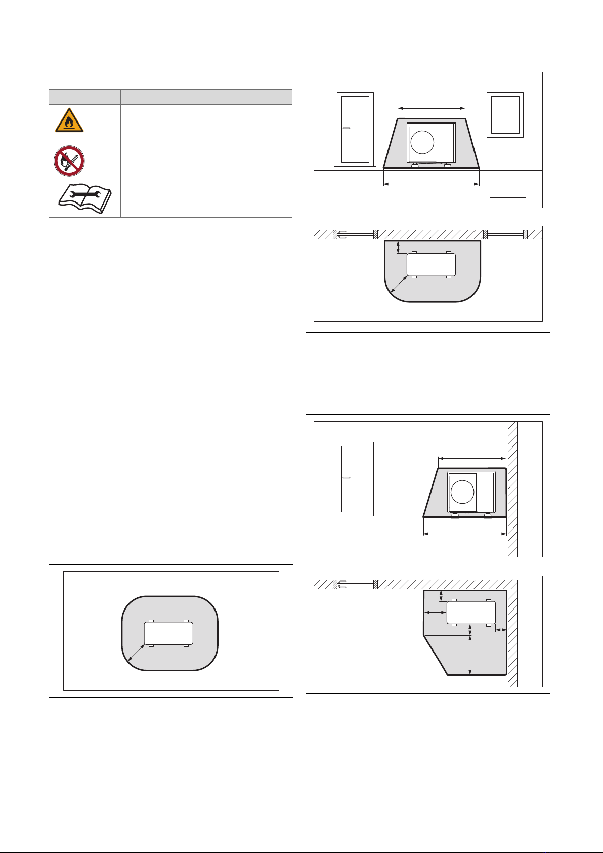
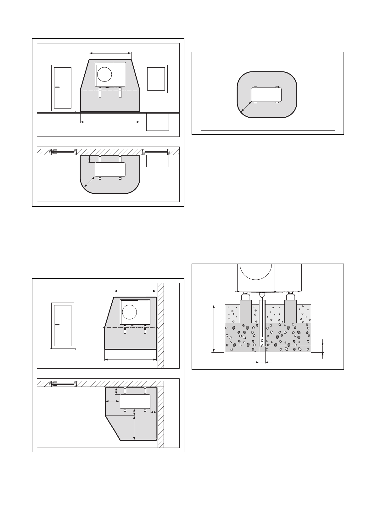
A protective zone is defined for the area
close around the product. See section
"Protective zone".
▶Ensure that there are no ignition sources,
such as plug sockets, light switches,
lamps, electrical switches or other per-
manent ignitions sources, in the protective
zone.
▶Do not use any sprays or other combust-
ible gases in the protective zone.
1.3.2 Risk of death due to changes to the
product or the product environment
▶Never remove, bridge or block the safety
devices.
▶Do not tamper with any of the safety
devices.
▶Do not damage or remove any tamper-
proof seals on components.
▶Do not make any changes:
–The product itself
–To the supply lines
–On the drain pipework
–On the expansion relief valve for the
heat source circuit