6
may set the potentiometers somewhere in the middle to get extra time before activating the
Failsafe. If the generator goes online before the timer times out the Failsafe will return to
“Normal Condition”. If the Generator fails to go online the Failsafe will transfer to Emergency
Power sending the Actuator to its Failsafe position.
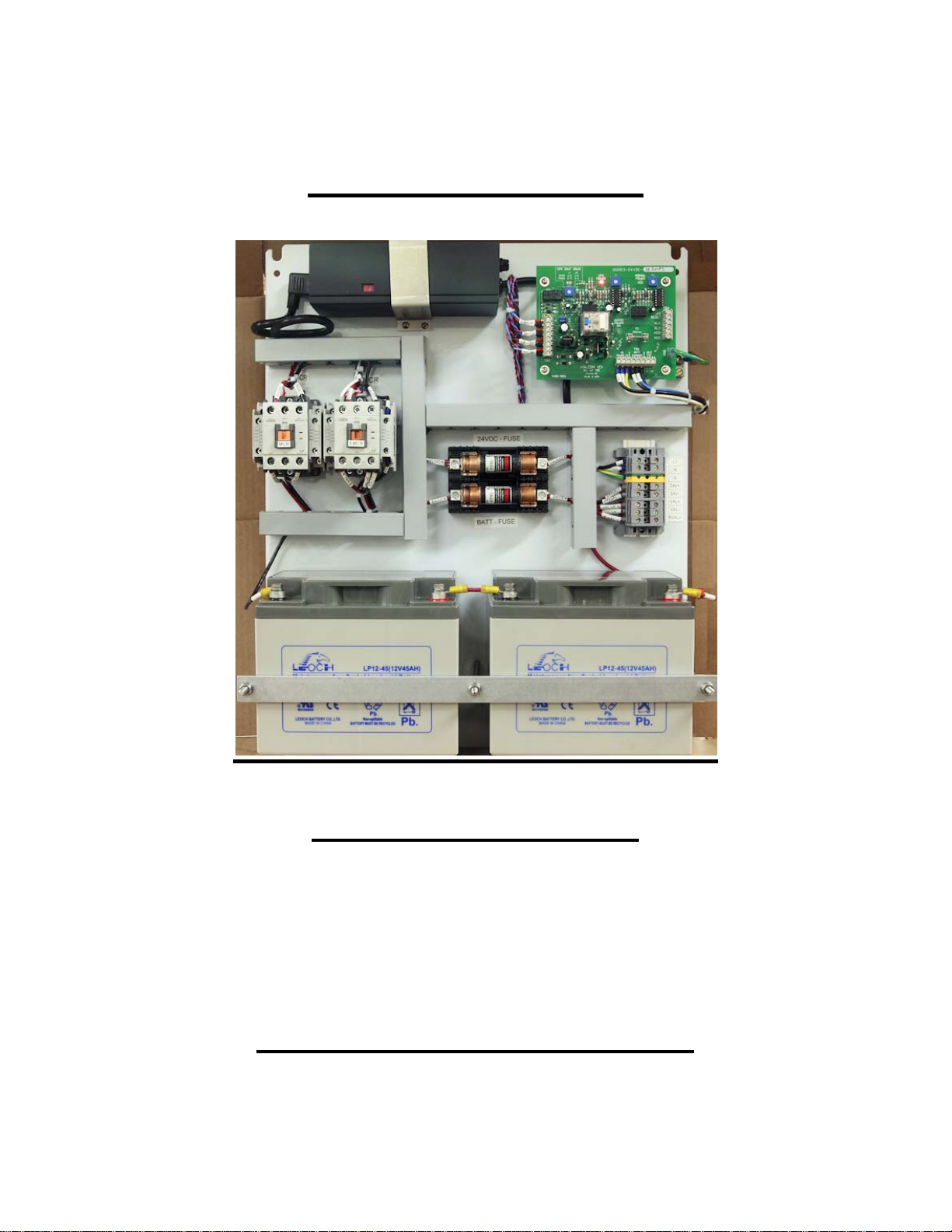
The Controller incorporates LED lights that show the type of power that the actuator is
receiving; these lights will be ON only when either Power has been applied to the actuator
terminal block.
Green NORMAL POWER LED = When lit actuator is receiving Normal Power.
Red UPS POWER LED = When lit actuator is receiving UPS power.
Green POWER LED = When lit Normal Power is present.
Clear UPS SHUT DOWN LED = When lit Failsafe has completed emergency cycle.
5. - Maintenance
The Failsafe unit requires minimum maintenance but should be kept dry and clean at all times,
periodically check all cable connections to the battery, clean and tighten these as necessary.
At least once a month test the system to make sure that the unit is in good condition and to
exercise the batteries.
Caution: blown fuses are an indication of a fault in the system or its connections. Such as short
circuits, overloads etc.. Locate the source of the problem before replacing the fuse.
The Failsafe unit operates at high efficiency and generates minimal heat during use. To ensure
that you will always get the maximum output from the Failsafe unit, periodically verify that the
battery is fully charged.
5.1 Testing the Batteries
Test the Failsafe unit once a month, cut the power supply to the Failsafe unit or use a Remote
test switch. Allow the actuator or actuators to move to there failsafe position, once they are in
failsafe mode reconnect power to the unit and check that all the relays are working properly, this
is also a good time to verify that the battery charger is working, the charging light should remain
ON (Yellow) until the battery reaches a fully charged condition.
You may check the condition of the battery with an Industrial sealed battery load tester, when
testing follow the instructions supplied with the battery load tester unit.
A quick test may be perform to check the condition of the battery, connect a volt-meter to the
battery terminals, disconnect power to the Failsafe unit and allowed the actuator to go to the
failsafe position, during all this time check the reading of the volt-meter, if the voltage do not