Valor GV60CKO User manual

4006080-02
GV60CKO
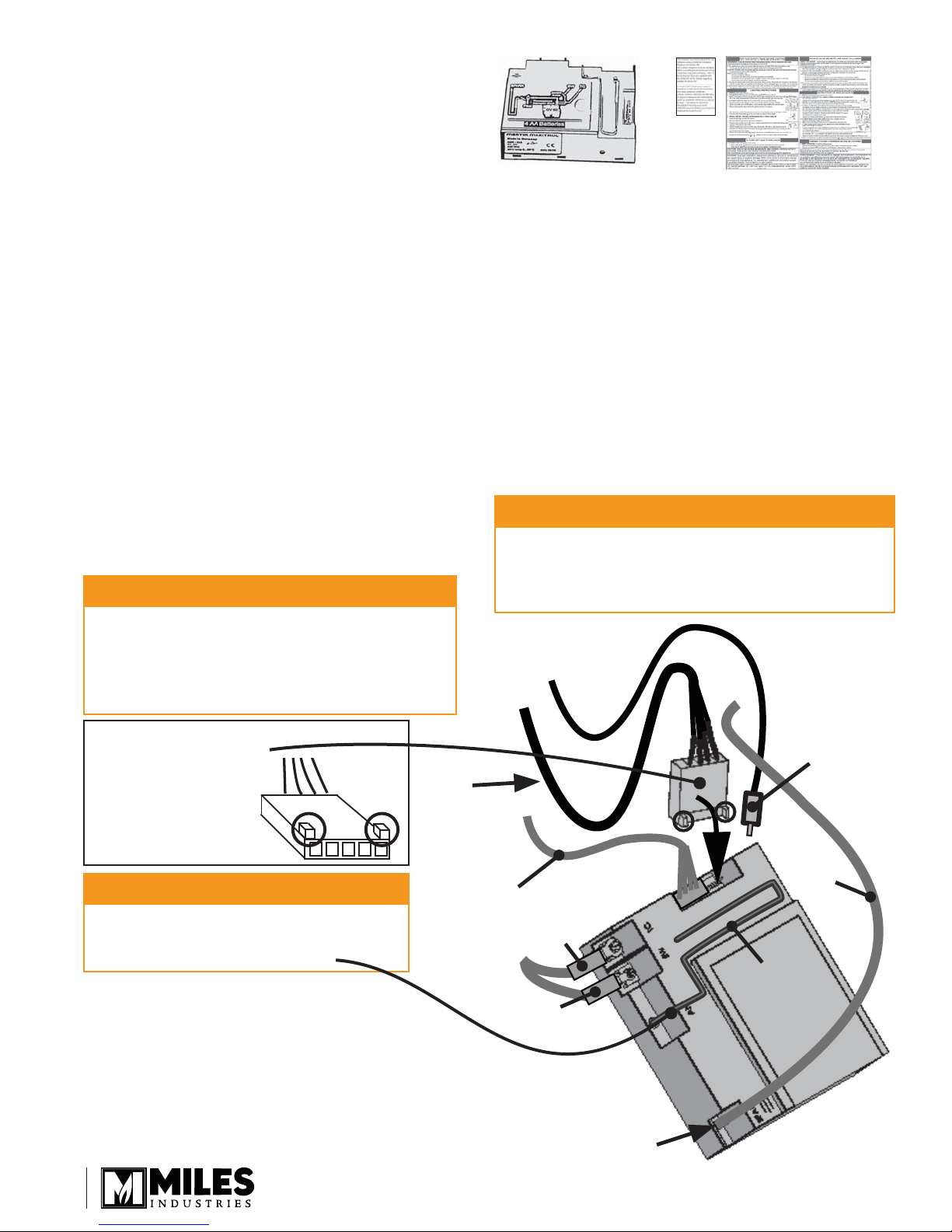
DO NOT USE thermostatic handset supplied
with appliance when installing outdoors!
USE 1265WSK or RBWSK (appliance
installed under overhang)
FIREPLACE
BATTERY
ACCESS
UP
ON-OFF
DOWN
ACCÈS
PILES
DU FOYER
XX
© Copyright Miles Industries Ltd., 2017.
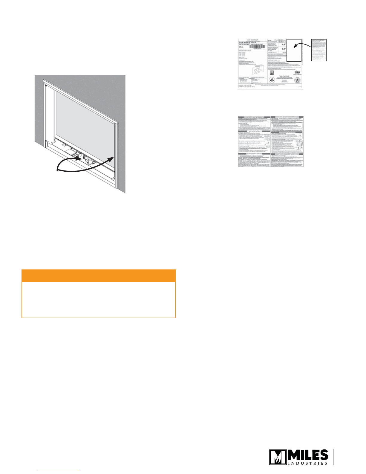
GV60 Outdoor Fireplace Conversion Kit
Installation Instructions
Use with with Valor Models 530 (ZC only), 534, 650, 1100, 1150, 1400,
1500, 1600, 1700, 1800 Heaters ONLY
WARNING
This conversion kit shall be installed by
a qualifi ed service agency in accordance
with the manufacturer’s instructions and
all applicable codes and requirements of
the authority having jurisdiction. If the
information in these instructions is not
followed exactly, a fi re, explosion or pro-
duction of carbon monoxide may result
causing property damage, personal injury
or loss of life. The qualifi ed service agency
is responsible for the proper installation of
this kit. The installation is not proper and
complete until the operation of the con-
verted appliance is checked as specifi ed in
the manufacturer’s instructions supplied
with the kit.
Use this manual in conjunction with the in-
stallation manual supplied with the appliance.
LEAVE THIS MANUAL WITH
THE HOMEOWNER.
WARNING
Electrical shock hazard - Do not install elec-
trical accessories (fans and lighting) when
converting the appliance for use outdoors.
!
!
General notes regarding conversion
This manual contains instructions for adapting natural
gas or propane models listed above for use outdoors.
For the purpose of this manual the term “outdoor”
means installed outside of the insulated building
envelope within a weatherproof enclosure having
a minimum required overhang. The outdoor space
may be attached or free standing to the main/primary
structure and may or may not include walls. See
page 6 for further information regarding locating your
outdoor fi replace.
Use this manual in conjunction with the installation
manual supplied with the appliance. The outdoor
fi replace must be permanently situated and connected
to a fi xed piping system and must not be portable.
Notes
• No electrical accessories (fans or lighting) permitted
when adapting the appliance for outdoor use.
• Any of the optional available trims and fronts may
be used in the outdoor environment including
optional HeatShift components although please
note that some fading or corrosion may occur due to
environmental conditions. Cast iron fronts are not
recommended outdoors.
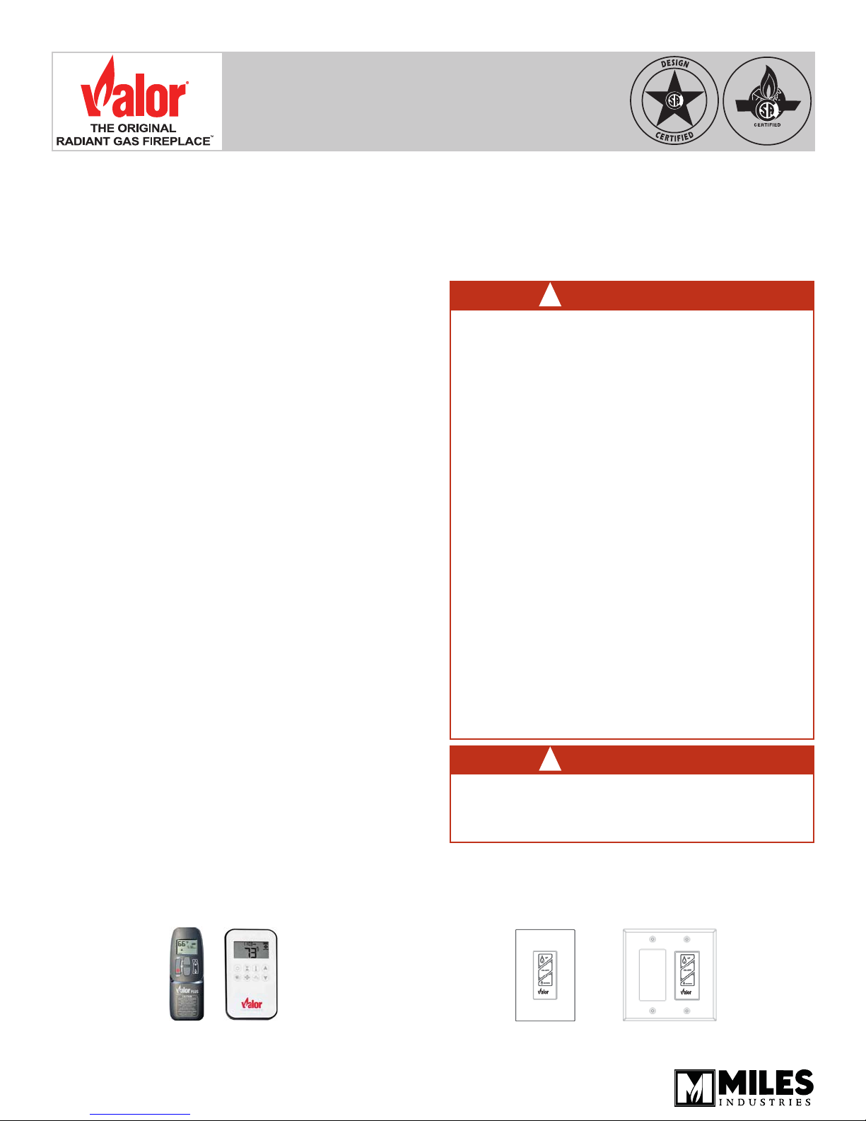
• Thermostatic controls are not allowed for outdoor
fi replaces. Use the wall switch supplied with the
appliance or when not supplied, order an optional
RBWSK Remote battery and wall switch kit to control
the appliance. Do not use the thermostatic
remote controled handset supplied with the
appliance!
1265WSK–
Wall Switch
RBWSK–Remote
Batteries & Wall Switch Kit

2
CAUTION
DO NOT USE a screwdriver or other metallic
object to remove the batteries from the receiver or
the handset! This could cause a short circuit to the
receiver.
CAUTION
To avoid short-circuit to the receiver,
position the antenna so that it DOES
NOT TOUCH the ignition wire.
Ignition Wire Connection
(spade type connector)
Be careful when removing and
reinstallaing: not to bend or
break the spade connector
Ignition
Wire
Antenna
Replace the existing receiver
Locate the existing receiver on the appliance. The
receiver is held in place by Velcro on most appliances.
Refer to the appliance’s manual if necessary.
1. Detach the receiver and pull it out of the appliance
to disconnect it. Be careful not to pull too hard
as you could damage the wire connections,
particularly the ignition wire connection.
2. Remove all the wires connected to the receiver and
set the receiver aside.
3. Connect the outdoor receiver (G6R-R3AMC) to the
existing wiring. DO NOT INSTALL BATTERIES
YET! Ensure no batteries are installed in the
RBWSK if used. Connections on the outdoor
receiver are identical to the existing receiver. See
diagram below.
Valve Wire
Harness
Red
Yellow
Wall Switch
Harness
RBWSK—
Remote Battery
Wall Switch kit
power connector
IMPORTANT: The
connection can only be
done one way. Do not
force it or damage the
pins on the receiver
box!
4. Install and connect the wall switch supplied with
the appliance to the receiver following instructions
provided with the appliance’s installation manual;
if the appliance is not supplied with a wall switch,
connect the RBWSK—Remote battery and wall
switch kit (supplied separately) to the outdoor
receiver—see installation instructions supplied with
the kit.
5. Insert 4 AA alkaline batteries into the outdoor
receiver or the RBWSK kit only after all connections
are completed.
6. Test the operation of the wall switch—see
appliance’s or wall switch kit instructions manual.
CAUTION
DO NOT PUT BATTERIES IN THE REMOTE
CONTROL RECEIVER OR RBWSK until the
wires are connected to the burner control unit as
short-circuit could result in the destruction of the
electrical components.
Take the switch wire and plug it into the receiver’s
connection slot as indicated.
Kit Contents
1 GV60 outdoor receiver with conformal coating—
to resist weather—part no. 4005111
1 Overlay conversion label—part no. 4006081
1 Outdoor Lighting Instructions card—part no. 4005169
G6R-R3AMC—
Outdoor receiver Conversion label and
Lighting Instructions

3
CAUTION
Be careful when using a hose or pressure washing
to clean the areas around the fi replace.
NEVER SPRAY WATER DIRECTLY AT THE
FIREPLACE!
Cleaning AROUND Your Fireplace
Your Valor outdoor gas fi replace will tolerate moderate
amounts of water on an occasional basis but is not
designed to be waterproof.
Ensure the fi replace is turned off - including pilot -
before performing any cleaning around it. Use plastic
sheeting to protect the fi replace front and trim from
direct spray while cleaning. Ensure all plastic is
removed before operating fi replace.
Exposure to outdoor UV light
Exposure to outdoor UV light will cause some plated
and painted fi nishes to fade over time. This fading is
unavoidable and not covered under warranty.
To minimize fading, locate the fi replace away from
direct sunlight. Decommissioning and covering the
fi replace over the off -season will also prolong the fi nish.
Decommission During Off -Season
We recommend decommissioning your outdoor
fi replace during the off -season when it will not be used
for an extended period. Decommission your fi replace
by removing the batteries from the battery holder and
turning the gas shut-off valve to the “off ” position.
Upon ensuring the fi replace cannot be turned on you
can then apply a weather protective cover over the
front of the fi replace to help preserve the fi nish and
further protect the appliance from weather.
Note: Do not operate your outdoor fi replace
during cold weather below freezing point
(32°F, 0°C).
Fix the conversion label and replace
the lighting instructions
The data label and lighting information cards are
located either under the fi rebox near the gas valve or
on the right side of the fi rebox. They are retained to the
appliance by a wire.
Data label and lighting
instructions located near the
gas valve or to the right of
fi rebox
1. Fix the conversion label on the data card as
indicated.
2. Remove the existing lighting instructions by cutting
the card out near its fi xing point.
3. Staple the new lighting instructions to the data card
near its fi xing point.
4. Place back in appliance.
fi replace
data card
lighting
instructions
conversion
label
Supplementary Owner’s Information

4
Lighting Instructions for Outdoor Fireplace Use
FOR YOUR SAFETY, READ BEFORE LIGHTING
WARNING: If you do not follow these instructions exactly, a fi re or explosion may result
causing property damage, personal injury or loss of life.
A. This appliance has a pilot which must be lighted by hand or wall switch. Follow these instructions exactly. To
save gas, turn the pilot off when not using the appliance for a prolonged period of time.
B. BEFORE LIGHTING, smell all around the appliance area for gas. Be sure to smell next to the fl oor because
some gases are heavier than air and will settle on the fl oor.
WHAT TO DO IF YOU SMELL GAS
• Do not try to light any appliance.
• Do not touch any electric switch; do not use any phone in your building.
• Immediately call your gas supplier from a neighbor’s phone. Follow the gas supplier’s instructions.
• If you cannot reach your gas supplier, call the fi re department.
C. Use only your hand to push in or turn the control knobs. Never use tools. If the knobs will not push in or turn by
hand, don’t try to repair them; call a qualifi ed service technician. Force or attempted repair may result in a fi re or
explosion.
D. Do not use this appliance if any part has been under water. Immediately call a qualifi ed service technician to
inspect the appliance and to replace any part of the control system and any gas control, which has been under water.
LIGHTING INSTRUCTIONS
1. STOP! Read the safety information above.
2. TO CLEAR ANY GAS, turn main valve off by pressing ON/OFF on wall switch (1).
• Wait fi ve (5) minutes to clear out any gas, then smell for gas, including near the fl oor. If you
smell gas, STOP! Follow “B” in the safety information above on this label. If you don’t smell
gas, go to the next step.
3. AUTOMATIC IGNITION: MAN-knob (2) in ON position. Ensure Flame Adjustment
knob (3) is set to lowest setting () (Fig. 1). Locate the pilot (Fig. 3.) inside of
fi rebox at left hand side.
• On the wall switch, press the ON button; a short acoustic signal confi rms the start
has begun.
• Further short acoustic signals indicate the ignition process is in progress.
• When the pilot is lit, the Flame Adjustment knob (3) will automatically rotate to
the highest setting.
• Press the small fl ame button () on the wall switch to reduce the fl ame height.
4. MANUAL IGNITION: MAN-knob (2) in MAN position (Fig. 2). With the window
off , locate the pilot (Fig. 3) inside of fi rebox at left hand side.
• Set Flame Adjustment knob (3) to the lowest setting ().
• Push down the metallic core (4) with a pen or similar instrument; this will establish
the pilot gas fl ow.
• Light gas at the pilot (5) with a match.
• Continue holding down metal core (4) for about 10 seconds; after release, pilot
should remain lit.
• If the pilot will not stay lit after several tries, turn the gas control knob (3) to OFF
() and call your local service technician or gas supplier.
• Reinstall the window and set the MAN-knob (2) to ON; turn Flame Adjustment knob (3) up () or down ()
manually or use the fl ame buttons ()() buttons on the wall switch to adjust the fl ame height.
TO TURN OFF GAS TO APPLIANCE
AUTOMATIC SHUT-OFF (using the wall switch):
• Press and hold the small fl ame button () on the wall switch to shut-off the main burner gas fl ow.
• Press ON/OFF button on wall switch to shut-off the appliance, including pilot fl ame.
Spark
Pilot
Fig 3
5
Fig 1
Fig 2
1
OFF

5
Min. required weatherproof
overhang in front and at sides of
replace is 1/2 of the height
of the overhang measured
from the base of the unit
1265WSK Wall switch or
RBWSK Remote battery
& wall switch kit
must be located within
weather protected area
Min. required
overhang
Vertical termination
recommended to
avoid ue products
from accumulating
in outdoor spaces
See appliance
manual and
page 12 of
this manual for
allowable vent
terminal locations
Min. required
overhang
Outdoor replace
installed in
weatherproof
enclosure
1
2
Location
For the purposes of this installation
manual the term “outdoor” means
installed outside of the insulated building
envelope within a weatherproof enclosure
having a minimum required overhang.
The outdoor space may be attached
or free standing to the main/primary
structure and may or may not include
walls.
Note: The fi replace will not perform
as an exterior wall. If installed against
an exterior wall we recommend the
appliance enclosure or chase be
constructed completely outside of the
insultated building envelope and weather
membrane.
The fi replace must be permanently
situated and connected to a fi xed piping
system, it is not portable.
Weather Protection/Moisture
Resistance
This outdoor fi replace will tolerate
moderate amounts of water on an
occasional basis but is not waterproof.
The fi replace must be enclosed in a
weatherproof enclosure clad in typical
weatherproof material such as siding/
stucco/stone/tile, etc. and have a
weatherproof structure to shed water
that extends horizontally beyond the front
and side perimeter of the fi replace (see
diagram).
Water running down vertical surfaces
should be directed away from the
fi replace using fl ashings. Measures must
be taken to ensure any accumulated
water drains away from the fi replace and
structure. When the fi replace is installed
on surfaces where water may collect or
cause damage a suitable drainage pan
should be placed under the unit and the
water drained away.
Top View (typical)
Side View (typical)

6
Min. weatherproof overhang
in front and at sides
Free standing structure
with weatherproof
overhang above
Weatherproof
enclosure
Weatherproof
enclosure
1600
See-
through
Continuous insulated building
envelope and weatherproof
membrane is NOT interrupted
by replace installation
INSIDE
INSIDE
OUTSIDE
Min. weatherproof overhang
in front and at sides
Sidewall vent terminations
within 7’ of grade or
where easily accessible
require a terminal guard
DO NOT INTERRUPT
BUILDING ENVELOP
WITH FIREPLACE
INSTALLATION!
See appliance
manual and
page of
this manual for
allowable vent
terminal locations
Typical Location

7
Combustible Overhang—Left Side View
Linear Series—1500, 1600, 1700, 1800
0 2” 4” 6” 8” 10” 12”
Bottom of appliance
Face of 1/2” thick
non-combustible
cement board
Do not put
furniture or objects
within 36” (914 mm)
of front of appliance
Min. required
weatherproof
overhang
Combustible
Mantel Projection
(from Face of Cement Board)
Combustible
Mantel
Height
(from Bottom
of appliance)
Fireplace
Opening
Combustible
Overhang
48” Min. to Combustible Overhang
(non-combustible construction permited lower)
44”
42”
40”
38”
33”
23-7/8”
9-3/8”
4” minimum to
combustible or
non-combustible hearth
Note: Use of the optional
LDK Duct Kits aff ects
mantel and hearth
clearances.
See instructions packed
with LDK Duct Kits.
not to scale

8
Combustible Overhang—Left Side View
H5 Series—1100, 1150
Bottom of Unit
02”1” 4” 6” 8” 10”12”
Do not put
furniture or objects
within 36” (914 mm)
of front of appliance
Mantel Projection
(from Face of Cement Board)
Mantel
Height
(from
Bottom
of Unit)
49”
47”
45”
43”
41”
4” minimum to combustible floor
or hearth. See Hearth Requirements
section of this manual.
Overhang
29”
54” Min. to Combustible Overhang
(non-combustible construction permited lower)
Min. required
weatherproof
overhang
Face of 1/2” thick
non-combustible
cement board
Note: Use of the optional
LDK Duct Kits aff ects
mantel and hearth
clearances.
See instructions packed
with LDK Duct Kits.
not to scale

9
Combustible Overhang—Left Side View
H6 Series—1400
Bottom of Unit
02”1” 4” 6” 8” 10” 12”
Do not put
furniture or objects
within 36” (914 mm)
of front of appliance
Mantel
Height
(from
Bottom
of Unit)
52”
50”
48”
46”
34-1/2”
4” minimum to combustible oor
or hearth. See Hearth Requirements
section of this manual.
58” Min. to Combustible Ceiling
(non-combustible construction permited lower)
Min. required
weatherproof
overhang
Combustible
Overhang
Combustible
Mantel Projection
(from Face of Cement Board)
Face of 1/2” thick
non-combustible
cement board
Note: Use of the optional
LDK Duct Kits aff ects
mantel and hearth
clearances.
See instructions packed
with LDK Duct Kits.
not to scale

10
Combustible Overhang—Left Side View
Horizon Series—534
Bottom of Unit
2”1” 3” 6” 8”
Do not put
furniture or objects
within 36” (914 mm)
of front of appliance
43-3/4”
40-3/4”
38-3/4”
37-3/4”
36-3/4”
29-3/4”
54” Min. to Combustible Overhang
(non-combustible construction permited lower)
Min. required
weatherproof
overhang
Combustible
Overhang
Combustible
Mantel Projection Mantel
Height
(from
Bottom
of Unit)
not to scale

11
Combustible Overhang—Left Side View
H4 Series—650
Bottom of Unit
4”2” 6” 8”10”12”
38”
36”
37”
34”
31-1/4”
35”
29-3/4”
54” Min. to Combustible Overhang
(non-combustible construction permited lower)
Min. required
weatherproof
overhang
Combustible
Overhang
Combustible
Mantel Projection
Do not put
furniture or objects
within 36” (914 mm)
of front of appliance
Mantel
Height
(from
Bottom
of Unit)
not to scale

12
Combustible Overhang—Left Side View
Portrait Series—530 (ZC engine only)
Bottom of Unit
6” 12”10”8”
Do not put
furniture or objects
within 36” (914 mm)
of front of appliance
44”
40”
42”
36”
54” Min. to Combustible Overhang
(non-combustible construction permited lower)
Min. required
weatherproof
overhang
Combustible
Overhang
Combustible
Mantel Projection Mantel
Height
(from
Bottom
of Unit)
not to scale

13
Horizontal Vent Terminal Locations
(see appliance manual for allowable vertical terminal locations)
V
G
A
Min. 72”
Max. 72”
Alcove detail
(open on one side)
Normal ceiling/
soffit clearances
apply.
KEY VENT TERMINAL LOCATIONS - MINIMUM DISTANCES MINIMUM
CLEARANCE
Inches Cm
A Clearance above grade, verandah, porch, deck or balcony 12 30
B Clearance to window or door leading to inside space that may be opened 12 30
C Clearance to permanently closed window (recommended to prevent condensation on window) 12 30
D Vertical clearance to ventilated soffi t located above the terminal within a horizontal distance of 2 feet (60
cm) from the center-line of the terminal
18 46
E Clearance to unventilated soffi t 12 30
F Clearance to outside corner 12 30
G Clearance to inside corner 12 30
H Horizontal clearance to center-line of meter/regulator assembly located within 15 feet (4,6 m) below the
terminal
36 90
I Clearance to service regulator vent outlet 36 90
J Clearance to non-mechanical air supply inlet to the building or the combustion air inlet to any other
appliance
12 30
K Clearance to a mechanical air supply inlet 72 180
L Clearance above paved sidewalk or a paved driveway located on public property
Note: A vent must not terminate directly above a sidewalk or paved driveway, which is located between
two single-family dwellings and serves both dwellings. THIS DOES NOT APPLY to direct vent, non-
condensing appliances in the Province of Ontario.
84 210
M Clearance under a verandah, porch, deck or balcony. Only permitted if veranda, porch, deck or balcony is
fully open on a minimum of 2 sides beneath the floor
12 30
Note: Local codes and regulations may require different clearances.
• This direct vent appliance is designed to operate when an
undisturbed airfl ow hits the outside vent terminal from any
direction.
• The minimum clearances from this terminal that must be
maintained are shown in the fi gure next page. Any reduc-
tion in these clearances could result in a disruption of the
airfl ow or a safety hazard. Local codes or regulations may
require greater clearances.
• The vent terminal must not be recessed into a wall
or siding.
• The vent terminal should be positioned where it will
not be covered by snowdrifts.
• Sidewall vent terminations within 7’ of grade or where eas-
ily accessible require a terminal guard such as the Valor
658TG or 845TG.
Vent Termination
•
The vent terminal must be located on a side wall or
through the roof. Where possible, venting through the roof
is preferable to sidewall venting to avoid products
of combustion from accumulating in outdoor spaces.
• Typically, outdoor spaces are not totally enclosed by solid
continuous walls. When sidewall venting is used, the
vent terminal will need to be located to avoid products of
combustion from accumulating within the outdoor space or
from entering the interior space through doors and win-
dows. See clearances listed below with respect to open-
ings to interior spaces.
• When a sidewall vent terminal terminates below an
overhead cover (either permanent or temporary cover) at
least 30% of the total perimeter wall area surrounding the
outdoor space must be openings.

14
Designed and Manufactured by / for
Miles Industries Ltd.
190–2255 Dollarton Highway, North Vancouver, BC, CANADA V7H 3B1
Tel. 604-984-3496 Fax 604-984-0246
www.valorfi replaces.com
Because our policy is one of constant development and improvement, details may vary slightly from those given in this publication.
1. Two-Year Parts Warranty
Two (2) years from the date of purchase, the Company, at its option, will repair or exchange all parts and components
that are found to have a ERQD¿GH defect in material or workmanship under normal conditions of use.
2. Conditions and Limitations
The warranty registration card must be completed by the initial owner and returned to the company within 90 days. Alternatively,
the warranty registration form may be filled out online at www.valorfireplaces.com
Installation and maintenance must be performed by an authorized and trained dealer in accordance with the Company’s installation
instructions.
This warranty is void where installation of the unit does not conform to all applicable codes including national and local gas
DSSOLDQFHLQVWDOODWLRQFRGHVDQGEXLOGLQJDQG¿UHFRGHV
The owner must comply with all operating instructions.
The Company is not responsible for the labor costs to remove defective parts or re-install repaired or replacement parts.
The initial owner of the unit will be responsible for any shipping charges for replacement parts as well as travel time
incurred by the dealer to perform the warranty work.
This warranty applies to non-commercial use and service and is void if it is apparent that there is abuse, misuse, alteration,
improper installation, accident or lack of maintenance to the unit.
This warranty does not cover damage to the unit due to:
i) Improper installation, operational or environmental conditions.
ii) Inadequate ventilation in the area or competition for air from other household equipment or appliances.
iii) Damage due to chemicals, dampness, condensation, or sulphur in the fuel supply lines which exceeds industry standards.
This warranty does not cover glass, log breakage or damage to the unit while in transit.
The Company does not allow anyone to extend, alter or modify this warranty and assumes no responsibility for direct, indirect or
FRQVHTXHQWLDOGDPDJHVFDXVHGE\WKHXQLW6WDWHRUSURYLQFLDOODZVZKHUHWKHLQLWLDORZQHURUXVHUUHVLGHVPD\SURYLGHVSHFL¿F
rights extending this warranty and, if so, the Company’s sole obligation under this warranty is to provide labor and/or materials in
accordance with those laws.
3. No Other Warranty
$OOREOLJDWLRQVWRUHSDLUWKLVXQLWDUHGH¿QHGLQWKLVZDUUDQWy6RPHVWDWHVRUSURYLQFHVPD\VSHFL¿FDOO\PDQGDWHDGGLWLRQDOREOLJDWLRQV
RQWKHSDUWRIPDQXIDFWXUHUVEXWLQWKHDEVHQFHRIVXFKVSHFL¿FOHJLVODWLRQWKHUHLVQRRWKHUZDUUDQW\RUREOLJDWLRQH[SUHVVHGRU
implied.
a)
b)
c)
d)
e)
f)
g)
h)
i)
j)
Outdoor Installations
Warranty
W
A
R
R
A
N
T
Y
P
R
O
G
R
A
M
W
A
R
R
A
N
T
Y
P
R
O
G
R
A
M
V
A
L
O
R
C
O
M
F
O
R
T
V
A
L
O
R
C
O
M
F
O
R
T
V
A
L
O
R
C
O
M
F
O
R
T
If you have a problem with this unit, please contact your dealer or
supplier immediately. Under no circumstances should you attempt
to service the unit in any way by yourself. The warranties in
paragraphs 1 are provided only to the initial owner of this unit,
are not transferable and are subject to the conditions and
limitations in paragraphs 2, 3. Please review the conditions
and limitations carefully and strictly follow their requirements.
Owner s
Information
For Outdoor Installations—
This warranty replaces the warranty
supplied with the appliance

15
LE PREMIER
FOYER À GAZ RADIANT
MC
®
NE PAS UTILISER la manette de télécommande
thermostatique avec le foyer installé à l’extérieur!
UTILISEZ LE 1265WSK ou RBWSK (installé dans
un endroit couvert)
GV60 Conversion pour foyer extérieur
Directives d’installation
Utilisez avec les foyers Valor 530 (ZC seulement), 534, 650, 1100, 1150, 1400,
1500, 1600, 1700, 1800 SEULEMENT
Concernant la conversion
Ce guide contient les directives pour adapter pour usage
extérieur les foyers listés ci-dessus, soit au gaz naturel
ou au gaz propane. Pour ce guide, le terme “extérieur”
désigne un foyer installé à l’extérieur des murs de
l’édifi ce dans un espace à l’épreuve des intempéries et
couvert d’un surplomb. L’espace extérieur peut être ad-
jacent ou séparé de la structure principale de l’édifi ce et
peut inclure des murs. Voir page 19 pour plus de rensei-
gnements concernant l’emplacement du foyer extérieur.
Utilisez ce guide conjointement avec le guide d’installa-
tion fourni avec le foyer. Le foyer extérieur doit être
situé de façon permanente dans son emplacement et
doit être raccordé à un réseau fi xe de tuyaux et ne doit
pas être portatif.
Notes
• Aucun accessoire électrique (ventilateur ou éclairage)
permis lorsque le foyer est adapté pour l’extérieur.
• Toutes bordures ou devantures optionnelles peuvent
être utilisées dans un environnement extérieur;
toutefois, veuillez noter que la couleur peut changer
et il peut y avoir de la corrosion dus aux conditions
climatiques. Les devantures de fonte ne sont pas
recommandées à l’extérieur.
• Les commandes thermostatiques ne peuvent pas
être utilisées sur les foyers extérieurs. N’utilisez que
l’interrupteur mural fourni avec le foyer ou, lorsque
non fourni, commandez le Porte-piles et interrupteur
mural RBWSK pour contrôler le foyer. NE PAS
UTILISER la manette thermostatique
de télécommande fournie avec l’appareil.!
FIREPLACE
BATTERY
ACCESS
UP
ON-OFF
DOWN
ACCÈS
PILES
DU FOYER
1265WSK–
Interrupteur
mural
RBWSK–
Porte-piles et
Interrupteur mural
XX
GV60CKO
AVERTISSEMENT
Ce kit de conversion doit être installé par
une agence de service qualifi ée selon les
directives du fabricant et tous les codes et
règlements applicables dans la juridiction
de l’installation. Dans les cas ou les direc-
tives de ce guide ne seraient pas suivies à
la lettre, un feu, une explosion ou la produc-
tion de monoxide de carbone pourraient se
produire et causer des dommages matéri-
els, des blessures ou la mort. L’agence de
service qualifi ée pour eff ectuer cette instal-
lation est responsible de l’installation ap-
propriée de ce kit. L’installation n’est com-
plète que lorsque l’opération de l’appareil
converti a été vérifi ée tel qu’indiqué par les
directives du fabricant fournies avec ce kit.
Utilisez ce guide en conjonction avec le
guide d’installation fourni avec le foyer.
LAISSEZ CE GUIDE AU CONSOMMATEUR.
AVERTISSEMENT
Risque de choc électrique - Ne pas install-
er d’accessoires électriques (ventilateur,
éclairage) lorsque le foyer est converti
pour usage à l’extérieur.
!
!

16
G6R-R3AMC—
Récepteur extérieur
Étiquette de conversion
et consignes d’allumage
MISE EN GARDE
N’UTILISEZ PAS de tournevis ou objet métallique
pour enlever les piles du récepteur ou de la manette
afi n d’éviter de court-circuiter la télécommande.
MISE EN GARDE
Afin d’éviter de court-circuiter le
récepteur, placez l’antenne de façon
à ce qu’elle NE TOUCHE PAS le fil
d’allumage.
Remplacez le récepteur du foyer
Repérez le récepteur du foyer. Le récepteur est main-
tenu en place par une bande Velcro dans la plupart des
foyers. Consultez le guide du foyer si nécessaire.
1. Détachez le récepteur existant et tirez-le hors de
l’appareil pour le débrancher. Faites attention de ne
pas tirer trop fort afi n de ne pas abîmer les bornes
des fi ls, particulièrement celle du fi l d’allumage.
2. Enlevez tous les fi ls branchés au récepteur existant
et mettez le récepteur de côté.
3. Branchez le récepteur pour l’extérieur (G6R-R3AMC)
aux fi ls existants. N’INSTALLEZ PAS LES PILES
POUR LE MOMENT! Assurez-vous qu’aucune
pile n’est installée dans le boîtier si le
RBWSK est utilisé. Les connexions au récepteur
extérieur sont identiques à celles du récepteur
original. Voir le schéma ci-dessous.
4. Installez et branchez l’interrupteur mural fourni avec
le foyer au nouveau récepteur selon les directives
fournies dans le guide d’installation du foyer; si le
foyer n’est pas équipé d’un interrupteur mural, bran-
chez le Porte-piles et interrupteur mural RBWSK
(vendu séparément) au récepteur extérieur—con-
sultez les directives d’installation fournies avec le kit.
5. Insérez 4 piles alcalines AA dans le récepteur
extérieur ou dans le Porte-piles RBWSK seulement
après avoir complété toutes les connexions.
6. Vérifi ez le fonctionnement de l’interrupteur—con-
sultez le guide du foyer ou de l’interrupteur mural
pour savoir comment fonctionne l’interrupteur.
Connexion du fi l d’allumage
(cosse)
Faites attention quand débranchez et
rebranchez le fi l d’allumage de ne pas
plier ou briser la cosse
Harnais
connexion
soupape
Rouge
Jaune
Harnais de
connexion
Interrupteur
mural
Connecteur
d’alimentation
du Porte-piles et
interrupteur mural
RBWSK
MISE EN GARDE
Ne placez pas les piles dans le récepteur
de la télécommande jusqu’à ce que les fils
aient été branchés à la soupape. Un court-
circuit pourrait se produire et détruire les
composantes électriques.
Contenu du kit
1 Récepteur pour l’extérieur GV60 avec
revêtement comforme—résistant aux conditions
atmosphériques—pièce no 4005111
1 Étiquette de conversion—pièce no 4006081
1 Carte de consignes d’allumage pour l’extérieur—
pièce no 4005169
i
on du
fi
l d’alluma
g
e
(
cosse
)
n
quand débranchez et
fi
l d’alluma
g
e de ne pas
p
lier ou briser la coss
e
n
R
ou
g
e
J
aun
e
C
onnecteur
d’a
lim
e
nt
a
ti
o
n
du Porte-piles et
interrupteur mural
R
BW
SK
Antenne
IMPORTANT : Le
connecteur ne peut
être branché que d’une
façon. Ne le forcez
pas car il pourrait
endommager les
fiches de contact du
récepteur!
Branchez le fi l de l’interrupteur dans la borne du
récepteur tel qu’indiqué.
Fil
d’allumage

17
Nettoyage AUTOUR de votre foyer
Votre foyer extérieur Valor tolérera, à l’occasion, une
quantité modérée d’eau mais il n’est pas imperméable
ou à l’épreuve de l’eau.
Assurez-vous que votre foyer est éteint - incluant la
veilleuse - avant de nettoyer autour. Utilisez des toiles
de plastiques pour protéger la devanture et bordure du
foyer lorsque vous nettoyez. Assurez-vous que toute
couverture de plastique est enlevée avant de faire
fonctionner votre foyer.
Exposition aux rayons UV à l’extérieur
L’exposition aux rayons UV à l’extérieur causera, avec
le temps, la décoloration des fi nis peints et plaqués.
Cette décoloration est inévitable et n’est pas couverte
par la garantie.
Pour minimiser la décoloration, situez le foyer à l’écart
des rayons directs du soleil. Le fait de mettre le foyer
hors service et de le couvrir durant la période ou il n’est
pas utilisé prolongera aussi la couleur des fi nitions.
Mise hors service pour une période prolongée
Nous recommandons de mettre votre foyer extérieur
hors service lorsque vous ne l’utiliserez pas pour
une période de temps prolongée. Mettez votre foyer
hors service en enlevant les piles du récepteur et en
tournant le robinet d’arrêt de gaz en position “off ”.
En vous assurant bien que le foyer ne peut se rallumer,
vous pouvez en couvrir la devanture avec une paroi
de protection à l’épreuve des intempéries afi n d’en
préserver le fi ni et de protéger l’appareil.
Note : Ne pas faire fonctionner le foyer extérieur
lorsque la température est au point de congéla-
tion ou plus froide (0° C, 32° F).
MISE EN GARDE
Faites attention lorsque vous utilisez le nettoyage
à pression pour nettoyer autour du foyer.
N’ARROSEZ JAMAIS DIRECTEMENT VOTRE
FOYER!
Renseignements additionnels pour les consommateurs
Apposez l’étiquette de conversion et
remplacez les consignes d’allumage
La carte de spécifi cations et les consignes d’allumage
sont situées soit sous la boîte de foyer à côté de la
soupape à gaz ou à la droite de la boîte de foyer. Elles
sont retenues au foyer par un fi l riveté.
Cartes d’information et
consignes d’allumage situées
près de la soupape à gaz ou à
droite de la boîte de foyer
1. Apposez l’étiquette de conversion sur la carte de
d’identifi cation de l’appareil à l’endroit indiqué ci-
dessous.
2. Coupez la carte des consignes d’allumage et
jetez-la.
3. Brochez la nouvelle carte de consignes d’allumage
à la carte d’identifi cation de façon à ce qu’elle
puisse être consultée au besoin.
4. Replacez les cartes d’identifi cation et d’allumage
dans le foyer.
carte d’identifi -
cation du foyer
carte des
consignes
d’allumage
étiquette de
conversion

18
Consignes d’allumage pour foyer utilisé à l’extérieur
Spark
Pilot
POUR VOTRE SÉCURITÉ LIRE AVANT D’ALLUMER
A. Cet appareil possède une veilleuse qui doit être allumée à la main ou avec l’interrupteur mural. Suivez ces instructions
à la lettre. Pour économiser l’énergie, éteignez la veilleuse lorsque vous n’utilisez pas l’appareil.
B. AVANT DE FAIRE FONCTIONNER, sentez tout autour de l’appareil pour déceler une odeur de gaz. Sentez près du
plancher, car certains gaz sont plus lourds que l’air et peuvent s’accumuler au niveau du sol.
QUE FAIRE SI VOUS SENTEZ UNE ODEUR DE GAZ :
• Ne pas tenter d’allumer d’appareil.
• Ne touchez à aucun interrupteur; ne pas vous servir des téléphones se trouvant dans l’édifi ce.
• Appelez immédiatement votre fournisseur de gaz depuis un voisin. Suivez les instructions du fournisseur.
• Si vous ne pouvez joindre le fournisseur, appelez le service des incendies.
C. Ne poussez ou ne tournez le bouton d’admission du gaz qu’à la main; ne jamais utiliser d’outil. Si le bouton reste
coincé, ne pas tenter de le réparer; appelez un technicien qualifi é. Le fait de forcer le bouton ou de le réparer peut
déclencher une explosion ou un incendie.
D. N’utilisez pas cet appareil s’il a été plongé dans l’eau, même partiellement. Faites inspecter l’appareil par un technicien
qualifi é et remplacez toute partie du système de contrôle et toute commande qui ont été plongées dans l’eau.
INSTRUCTIONS DE MISE EN MARCHE
1. ARRÊTEZ ! Lisez les consignes de sécurité ci-dessus.
2. POUR ARRÊTER L’ENTRÉE DE GAZ, éteignez la soupape en pressant sur le bouton
ON/OFF sur l’interrupteur mural (1).
• Attendez cinq (5) minutes pour laisser échapper tout le gaz. Vérifi ez autour de l’appareil et près
du plancher s’il y a une odeur de gaz. Si c’est le cas, ARRÊTEZ! Passez à l’étape B des
consignes de sécurité ci-dessus. S’il n’y a pas d’odeur de gaz, passez à l’étape suivante.
3. ALLUMAGE AUTOMATIQUE : Bouton MAN à ON (2). Assurez-vous que le bouton
de réglage des fl ammes (3) est au réglage le plus bas () (fi g. 1). Repérez la
veilleuse (fi g. 3.) à gauche dans la boîte de foyer.
• Sur l’interrupteur mural, appuyez le bouton ON/OFF; un court signal sonore indiquera
le début du procédé d’allumage;
• De courts signaux sonores seront entendus jusqu’à ce que le procédé d’allumage soit
complet et que le gaz ait circulé dans les tuyaux jusqu’à la soupape;
• Lorsque la veilleuse s’allumera, le bouton d’ajustement des fl ammes (3) tournera
automatiquement au réglage le plus haut;
• Appuyez sur le bouton petite fl amme ( ) pour réduire la hauteur des fl ammes.
4. ALLUMAGE MANUEL : Bouton MAN à MAN (2) (fi g. 2). Avec la fenêtre enlevée,
repérez la veilleuse (fi g. 3) à gauche dans la boîte de foyer.
• Réglez le bouton de réglage des fl ammes (3) à la température la plus basse ();
• À l’aide d’un objet pointu comme un stylo, appuyez sur le centre métallique (4) pour
établir l’arrivée du gaz à la veilleuse;
• Toujours en appuyant sur le centre métallique (4), allumez le gaz à la veilleuse (5) avec
une allumette;
• Continuez d’appuyer sur le centre métallique (4) pour à peu près 10 secondes; relâchez
et la veilleuse restera allumée.
• Si la veilleuse s’allume mais ne reste pas allumée après plusieurs essais, tournez le bouton d’alimentation de gaz
(3) à la position “OFF” () et appelez votre agent de service ou votre fournisseur de gaz.
• Replacez la fenêtre et mettez le bouton MAN (2) à la position ON; tournez le bouton de réglage des fl ammes (3) vers le
haut () ou le bas () ou utilisez les boutons des fl ammes ( ) ( ) sur l’interrupteur mural pour régler les fl ammes.
COMMENT COUPER L’ADMISSION DE GAZ À L’APPAREIL
ARRÊT AUTOMATIQUE (à l’aide de l’interrupteur mural) :
• Appuyez et maintenez le bouton petite fl amme ( ) pour arrêter l’alimentation de gaz;
• Appuyez sur le bouton ON/OFF pour fermer la soupape et éteindre la fl amme de la veilleuse.
Fig 3
5
Fig 1
Fig 2
MISE EN GARDE : Quiconque ne respecte pas à la lettre les instructions dans la présente
notice risque de déclencher un incendie ou une explosion entraînant des dommages, des
blessures ou la mort.
Étincelle
Veilleuse
OFF

19
Vue du dessus typique
Vue de côté typique
Interrupteur mural
1265WSK ou le
Porte-piles et
interrupteur mural
RBWSK doit être situé
dans un espace à
l’épreuve des
intempéries
Sortie verticale
recommendée pour
éviter que les produits
de combustion évitent
de s’accumuler dans
les espaces extérieurs
Consultez le guide du
foyer et ce guide à la
page 25 pour les
emplacements de
sortie d’évacuation
permis.
1
2
Surplomb à l’épreuve
des intempéries exigé
en avant et de chaque
côté du foyer d’un
minimum de 1/2 de la
hauteur du surplomb
mesurée à partir de la
base de l’appareil
Surplomb
minimum exigé
Surplomb
minimum exigé
Foyer extérieur installé
dans un encastrement
à l’épreuve des
intempéries
Emplacement
Aux fi ns de ce guide d’installation, le
terme “extérieur” désigne l’installation
en dehors de l’enveloppe d’isolation
d’un édifi ce dans un espace à l’épreuve
des intempéries avec un surplomb aux
dimensions minimales exigées. L’espace
extérieur peut être contigu ou autoportant
en rapport à la structure principale et
peut inclure des murs ou non.
Note : Le foyer ne peut être installé
à titre de mur extérieur. Si le foyer
est installé contre un mur extérieur,
nous conseillons la construction de
l’encastrement ou de la charpente
complètement en dehors de l’enveloppe
du bâtiment et du revêtement
d’étanchéité.
Le foyer doit être installé de façon
permanente et raccordé à un système de
tuyauterie fi xe; il n’est pas portatif.
Protection contre les intempéries
/ résistance à l’humidité
Ce foyer extérieur tolérera à l’occasion
une quantité modérée d’eau mais n’est
pas imperméable.
Le foyer doit être encastré dans une
charpente à l’épreuve des intempéries
recouverte de matériaux à l’épreuve
des intempéries (étanches) tels que
parement/stucco/pierre/tuile, etc. et
avoir une structure à l’épreuve des
intempéries évacuant l’eau et s’étendant
horizontalement au-delà du devant et
des côtés du foyer (voir schéma).
L’eau s’écoulant le long des surfaces
verticales devrait être dirigée à l’écart
du foyer à l’aide de solins. Des mesures
doivent être prises afi n d’assurer que
toute accumulation d’eau puisse être
drainée à l’écart du foyer et de la
structure qui le contient. Lorsque le foyer
est installé sur une surface où l’eau peut
s’accumuler ou causer des dommages,
un bac d’égouttement approprié devrait
être placé sous l’appareil et l’eau
drainée.

20
1600
à 2
faces
INTÉRIEUR
INTÉRIEUR
EXTÉRIEUR
NE PAS INTERROMPRE
L’ENVELOPPE DE
L’ÉDIFICE AVEC
L’INSTALLATION
D’UN FOYER!
Voir guide du foyer
et page 24 de ce guide
pour emplacements
de sortie d’évacuation
permis
Structure autoportante
avec surplomb à l’épreuve
des intempéries
Encastrement
à l’épreuve des
intempéries
Encastrement
à l’épreuve des
intempéries
Enveloppe isolante continue de
l’édice et membrane à l’épreuve
des intempéries NE SONT PAS
interrompues par l’installation du foyer
Taille minimale du surplomb à
l’épreuve des intempéries à
l’avant et de chaque côté du foyer
Taille minimale du surplomb à
l’épreuve des intempéries à
l’avant et de chaque côté du foyer
Les sorties d’évent au mur
situées à 7 pieds ou moins
d‘un endroit accessible
doivent être couvertes par
un grillage de protection
Emplacement typique
Other manuals for GV60CKO
1
Table of contents
Languages:
Popular Outdoor Fireplace manuals by other brands

Home Decorators Collection
Home Decorators Collection AVONDALE WICKER FHWS80124 Use and care guide

Sunnydaze Decor
Sunnydaze Decor WAR-962 owner's manual

Nuu Garden
Nuu Garden AF001 instruction manual

Bond
Bond Belden owner's manual

HAPPATIO
HAPPATIO HPO-HPZ-M-H owner's manual

Hiland
Hiland F-1201-FPT owner's manual

for Living
for Living A301002300 manual

Four Seasons Courtyard
Four Seasons Courtyard 99000 Assembly instructions

Regency Fireplace Products
Regency Fireplace Products Plateau PTO50 Owners & installation manual

Blumfeldt
Blumfeldt Caruso manual

Oypla
Oypla HOME 3144 user manual

tiki
tiki Fire Pit Screen manual