VALSTEAM ADCA M3HP User manual

abcde
ADCA
VALSTEAM
ADCA
IMI M3HP.10 E 03.15
INSTALLATION AND MAINTENANCE INSTRUCTIONS
HIGH PURITY BALL VALVES
M3HP TRUE BORE
GENERAL
These instructions must be carefully read before any work involving products supplied by VALSTEAM ADCA
ENGINEERING S.A. is undertaken.
The installation procedure is a critical stage in a life of a valve and care should be taken to avoid damage to the
valve or equipment.
They give their maximum performance only when the equipment associated with them is correctly sized and
installed in accordance with our recommendations.
M3HP three pieces body ball valves are isolating valves designed for use on clean steam, condensate and
other gases and liquids used in high purity and aseptic processes. The valve is not designed as a control valve
and should be used only as an isolating valve, fully open or fully closed.
The product was mainly designed for the pharmaceutical, biotech, semiconductor, cosmetics, fine chemical,
food and beverage industries.
Note:
Current regional safety regulations should be take in to account and followed, while doing the installation and
maintenance work.
Handling, installation and maintenance work must be carried out by trained personnel. A supervisor must follow
and check all activities.
For the problems that cannot be solve with the help of this instructions, please contact the supplier or the
manufacturer.
The manufacturer reserves the right to change the design and material of this product without notice.
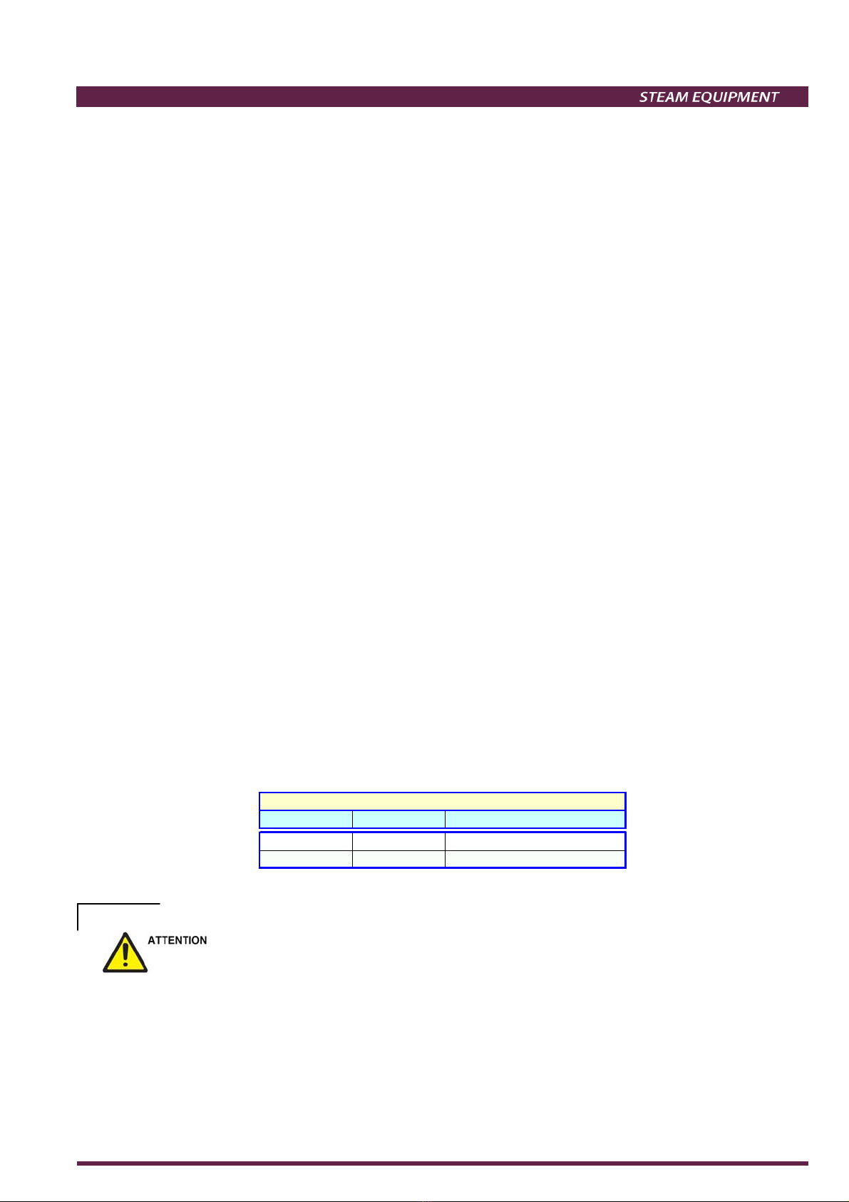
CE Marking: This product has been designed for use on water, clean steam and other liquids or gases which are in
Group 1 and 2 of the PED-European Pressure Equipment Directive 97/23/EC and it complies with those
requirements.
PN 100 PN 64 Category
DN 1/2" to 1" / SEP - art. 3, paragraph3
/ DN 11/2" -2" 1 (CE Marked)
CE MARKING (PED - European Directive 97/23/EC)
- If malfunction of any other equipment or system operation failure may result in a dangerous overpressure, over
temperature or even vacuum condition, a safety device must be included in the system to prevent such
situations.
- At start up, the presence of small particles in the fluid (dirt, scale, weld splatters, etc) may cause an imperfect
closure of the seat. If this occurs, proceed to an accurate cleaning.
- Do not touch the equipment without appropriate protection during working operation because it may conduct
heat if the used fluid is at high temperature.
- Before starting maintenance be sure that the equipment is not pressurized or hot.

abcde
ADCA
VALSTEAM
ADCA
IMI M3HP.10 E 03.15
- The equipments must be used within the working temperature and pressure limits laid down for them, otherwise
they may fail (refer to nameplate and/or IS- Information Sheet).
- Manual handling of products may present a risk of injury. You are advised to assess the risks taking into
account the task, the individual, the load and the working environment.
- Special care should be taken when harmful fluids (toxic, contaminant, corrosive, etc.) have flowed through the
valve. Recommended PPE (Personal Protective Equipments) should be use.
- Before starting work ensure that you have suitable tools and/or consumables available. Use only genuine ADCA
replacement parts.
- Do not remove the marking in the equipment. Serial number and other useful information is there.
- Do not apply the valve for oxygen service, if it hasn’t been specifically manufacture for that purpose.
- During the assembly work, apply protective measures against dirt and all kinds of contamination.
- The equipment should be carefully handled, to prevent any damage in its surfaces.
- Correct installation of the equipment is full responsibility of the contractor
- Valves are designed to be applied in places protected from exposure to weather.
CLEANING AND PACKING
This equipment is packed by a proper machine with a special film used by food industry.
These equipments are degreased and cleaned ultrasonically.
For oxygen application a special cleaning process is applied.
TRANSPORT AND STORAGE
- Handling and lifting of materials should be made with adequate equipments.
- The valves and equipments should be protected from impacts and forces during transportation and storage.
- We advice that all the protective packing in the valves, is kept during storage to avoid damage and
contamination. The environment should be as clean and dry as possible.
- The valve should be in fully open or closed position to prevent the ball edges to cause damage to the seats.
- The manufacturer doesn’t assume the responsibility of damaged equipments due to inappropriate handling
during the transportation and storage.
INSTALLATION
- Account for over pressure conditions, according with the local laws or standards.
- Valve mountings such as actuators, handwheels, hoods must not be used with other purpose than the one they
were built for (e.g. climbing aids or as connecting points for lifting gear)
- For the problems that cannot be solve with the help of this instructions, please contact the supplier or the
manufacturer.

abcde
ADCA
VALSTEAM
ADCA
IMI M3HP.10 E 03.15
Installation area requirements:
The installation area should have easy access and provide enough space for maintenance and removing
operations.
Procedure:
Prior to install check that the product is suitable for the intended application: materials and
pressure/temperature ratings.
Before installing remove plastic covers placed on flanges or connection ends.
Take care with jointing material to ensure that none may be permitted to block or enter the valve.
External stresses that may be induced by the system due to pipe expansion, etc, can affect this product. The
necessary precautions are recommended during the systems design and equipment assembly.
The valve pipework should be properly supported and free from strain and it should not be subjected to undue
surges of pressure.
This valves can be installed in any direction and way.
In case of clamps connections do not over-tighten them because that can damage the gasket.
The M3HP with tube weld connections don't need to be disassembled prior to welding procedure, nevertheless
sometimes disassemble it can became more practical for the welder due to weight, especially in bigger valves.
In those cases follow these steps:
1. Remove the bolts to separate the valve body from the body connectors;
2. Carefully remove the body seals and put them on a clean surface along with the body;
3. Prepare the surfaces to be welded;
4. Fit the connectors with the flange into the pipe and proceed with the welding according to the applicable
standards and good practices. Note that the flanges don´t need to be align since they can rotate freely to meet
any required valve body position;
5. Let the welding surfaces cold down and clean them to remove weld slag and other particles that can cause
seal and seat damage during startup;
6. Pick up the valve body, turn the ball into the closing position to prevent any seat damage during the assembly
and install the body seals;
7. Assemble the valve body into the welded connectors by putting the flange bolts in place and tighten them
evenly in a diagonal pattern. Before the final tightening, align the valve by rotating the complete set into the
desired position;
NOTE: When welding the valve completely assembled, the welder must guaranty that the valve is fully
closed, otherwise unevenly seats deformation may occur during the heat transmission.
Apart from being welded assembled or disassembled, a pipe flushing may be necessary to assure a proper
cleaning of the system.

abcde
ADCA
VALSTEAM
ADCA
IMI M3HP.10 E 03.15
START UP
- Current regional safety regulations should be take in to account and followed.
- Protective insulation and warning notice may be required.
- Until the start up of an existing or a new plant, the following must be checked:
- All works are completed;
- The valve is correctly installed;
- All the necessary safety devices have been installed;
- At start up, the presence of small particles in the fluid may cause an imperfect closure of the seat. If this
occurs, proceed to an accurate cleaning.
Procedure:
1. Stop valve should be closed.
2. Turn the lever slowly to open the stop valve and prevent hammering effects or sudden pressure increase on
downstream equipments and pipeline. M3HP ball valves are 1/4 turn open/close valves. When the lever is in
line with the pipeline the valve is open, when is perpendicular it's closed.
3. The valve is ready.
Periodical checking:
24 hours after the start up, it is recommended to check pipe connections for leaks and retighten the connections
if necessary.
MAINTENANCE
We recommend the ball valves to be serviced as necessary. Ball valves should be checked periodically (at least
yearly), to verify if they are operating correctly, if they have any leakages and to clean the internal parts if
necessary.
When reassembling make sure that all gasket faces are clean and use a new gasket if required.
Lubrication must be avoided for oxygen service. When it’s necessary, only the lubricants recommended by the
manufacture should be use.
During maintenance operations care should be taken to avoid any scratches or damage in the ball surfaces,
seals and seats. Leakage and other malfunctions may result from that.
Maintenance should proceed as follows:
Disassembling the valve for seats, body seals or ball replacement:
1. Unscrew all the bolts (17) from the body;
2. Take out the valve body with the ball (6) in the open position;
3. Put the ball in the close position;
4. Carefully remove the body seals (9) and seats (7,8) without damaging their surfaces. Caution to prevent the
ball to fall off;
5. Carefully remove the ball (6) from the valve body without damaging the surfaces;
6. Inspect the body seals, seats and ball for any damages and replace for new parts if necessary;

abcde
ADCA
VALSTEAM
ADCA
IMI M3HP.10 E 03.15
7. Reassemble all the components in reverse order except the bolts. Make sure all components are in good
conditions and free from dirt or any other impurities that may cause future failures;
8. With the ball in close position, tighten the bolts evenly in a diagonal pattern. Before the final tightening, align the
valve by rotating the complete set into the desired position;
9. Consider the start up conditions;
Stem assembly maintenance:
1. Repeat previous steps from 1 to 6;
2. Unscrew the bolt (19) and remove the lever;
3. Remove the lock washers (16) and unscrew the compression nut (15);
4. Remove the belleville spring washers (14) and the spacer (11);
5. Remove the stem seals (10);
6. Carefully push the stem (5) into the body to remove it;
7. Replace all the stem seals and the o-ring (10,21) for new ones;
8. Inspect the spring washers for any excessive deformations and replace if required;
9. Reassemble all the components in reverse order except the bolts. Make sure all components are in good
conditions and free from dirt or any other impurities that may cause future failures. The compression
nut should be tighten just the enough to exert pressure over the stem seals.
10. With the ball in close position, tighten the bolts evenly in a diagonal pattern. Before the final tightening, align the
valve by rotating the complete set into the desired position;
11. Consider the startup conditions;

abcde
ADCA
VALSTEAM
ADCA
IMI M3HP.10 E 03.15
TROUBLESHOOTING
- If the malfunctions cannot be solved with the help of the following chart, please consult the manufacture.
TROUBLE SHOOTING CHART
FAULT POSSIBLE REASON SOLUTION
Leakage at body joints Untighten fixing bolts
Damaged body seals
Retighten the fixing bolts (17). If the problem
remains, disassemble the valve body and change
the body seals (9).
Stem leakage Loosen spring washers
Damaged stem seals
Remove the lever (12,13), the lock washer (16)
and inspect. If the spring washers (14) are in
good conditions but loosen, retighten the
compression nut (15); if the spring washers are
damaged remove the compression nut and
replace the spring washers.
If the leakage remains disassemble the stem
assembly, check if the stem seals (10) are
damaged and replace if necessary.
Leakage through the valve
Damaged seats
Damaged ball surfaces
Check, with the valve closed, if there's flow at the
valve outlet. If yes, than disassemble the valve
body and check for damages in the seats and ball
surfaces. Replace for new ones if necessary.

abcde
ADCA
VALSTEAM
ADCA
IMI M3HP.10 E 03.15
SPARE PARTS
POS. DESIGNATION MATERIAL
1 Valve body AISI316L / 1.4404
2 TC end connection AISI316L / 1.4404
3 Tube weld end conn. AISI316L / 1.4404
4 Flange AISI316L / 1.4404
5 Stem AISI316L / 1.4404
6 * Valve ball AISI316L / 1.4404
7 * Standard seat TFM 1600
8 * Cavity filler seat TFM 1600
9 * Body seal PTFE
10 * Stem seals TFM 1600
11 * Spacer AISI316 / 1.4401
12 Lever AISI304 / 1.4301
13 Lever end AISI304 / 1.4301
14 * Spring washers AISI304 / 1.4301
15 Compression nut AISI304 / 1.4301
16 * Lock washers AISI304 / 1.4301
17 Fixing bolt AISI304 / 1.4301
18 Stop pin AISI304 / 1.4301
19 Fixing screw AISI304 / 1.4301
20 Antistatic device AISI316 / 1.4401
21 O-ring VITON
Remarks: FDA/USP Class VI seals certificate on request
All valves have a serial number. In case of non-standard
valves this number must be supplied if spare parts are ordered.
* Available spare parts. ** On request
MATERIALS
PRODUCTS RETURNING
- Information regarding any hazards and precautions to be considered because of contaminating fluids and
residues or mechanical damage that may represent a health, safety or environmental risk, must be provided in
writing by the distributors and costumers when returning products to Valsteam ADCA engineering.
- Health and safety data sheets regarding substances identified as hazardous or potentially hazardous must be
provided with the information mention above.
- LOSS OF GUARANTEE: Total or partial disregard of above instructions involves loss of any right to guarantee.
Table of contents
Other VALSTEAM ADCA Control Unit manuals
Popular Control Unit manuals by other brands

WOMIX
WOMIX MIX M Series Mounting and operating instructions

Neosun Energy
Neosun Energy NS48112-P user manual

Alpha Outback Energy
Alpha Outback Energy Cordex 24-400W manual

BENDIX
BENDIX AR-2 ANTILOCK RELAY VALVE manual

Mitsubishi Electric
Mitsubishi Electric MELSEC iQ-R60DA4 Startup User's Manual

DoorBird
DoorBird D21 Series manual

Pentair
Pentair Raychem PMKG-LE installation instructions

Base
Base LV-8RS Installation and operation manual

ICP DAS USA
ICP DAS USA I-7045 quick start guide

Exar
Exar XR77XXEVB-XCM-V80 manual

Blackrock Microsystems
Blackrock Microsystems CerePlex m Instructions for use

M-system
M-system R7C-TS4 instruction manual