Valveworks M Series Instruction manual

SIZE WP (PSI) A B C D E NT RJ BSS N WT
(LBS)
HT
(FT-LBS)
2 1/16
2K 11 5/8 2 1/16 5 1/4 19 1/2 10 14 R-23 5/8 8 120 32
3K 14 5/8 2 1/16 5 1/2 19 5/8 13 14 R-24 7/8 8 180 40
5K 14 5/8 2 1/16 5 1/2 19 5/8 13 14 R-24 7/8 8 180 57
2 9/16
2K 13 1/8 2 9/16 6 3/8 20 1/2 13 16 1/2 R-26 5/8 8 180 37
3K 16 5/8 2 9/16 6 5/8 20 7/8 16 16 1/2 R-27 7/8 8 220 49
5K 16 5/8 2 9/16 6 5/8 20 7/8 16 16 1/2 R-27 7/8 8 220 66
3 1/8
2K 14 1/8 3 1/8 7 5/8 22 7/8 13 20 3/4 R-31 7/8 8 220 48
3K 17 1/8 3 1/8 7 5/8 23 16 20 3/4 R-31 1 8 300 65
5K 18 5/8 3 1/8 7 5/8 23 16 20 3/4 R-35 1 8 340 90
4 1/16
2K 17 1/8 4 1/16 9 5/8 26 1/2 16 24 3/4 R-37 1 8 360 81
3K 20 1/8 4 1/16 9 5/8 26 5/8 20 24 3/4 R-37 1 3/8 8 520 67
5K 21 5/8 4 1/16 9 5/8 26 5/8 20 24 3/4 R-39 1 3/8 8 560 130
5 1/8
2K 22 1/2 5 1/8 11 3/4 30 24 30 1/4 R-41 1 3/8 8 770 150
3K 24 1/8 5 1/8 11 3/4 30 24 30 1/4 R-41 1 3/8 8 810 210
5K 28 5/8 5 1/8 11 3/4 30 24 30 1/4 R-41 1 3/8 8 940 366
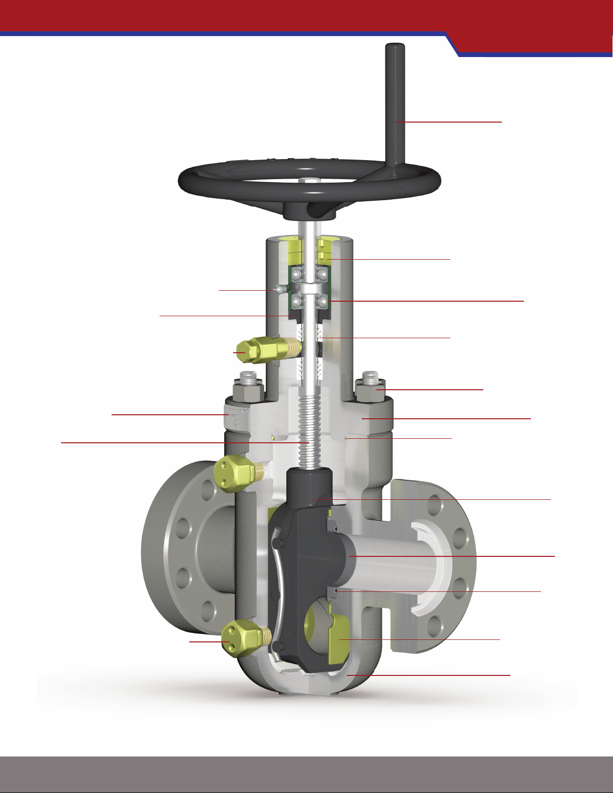
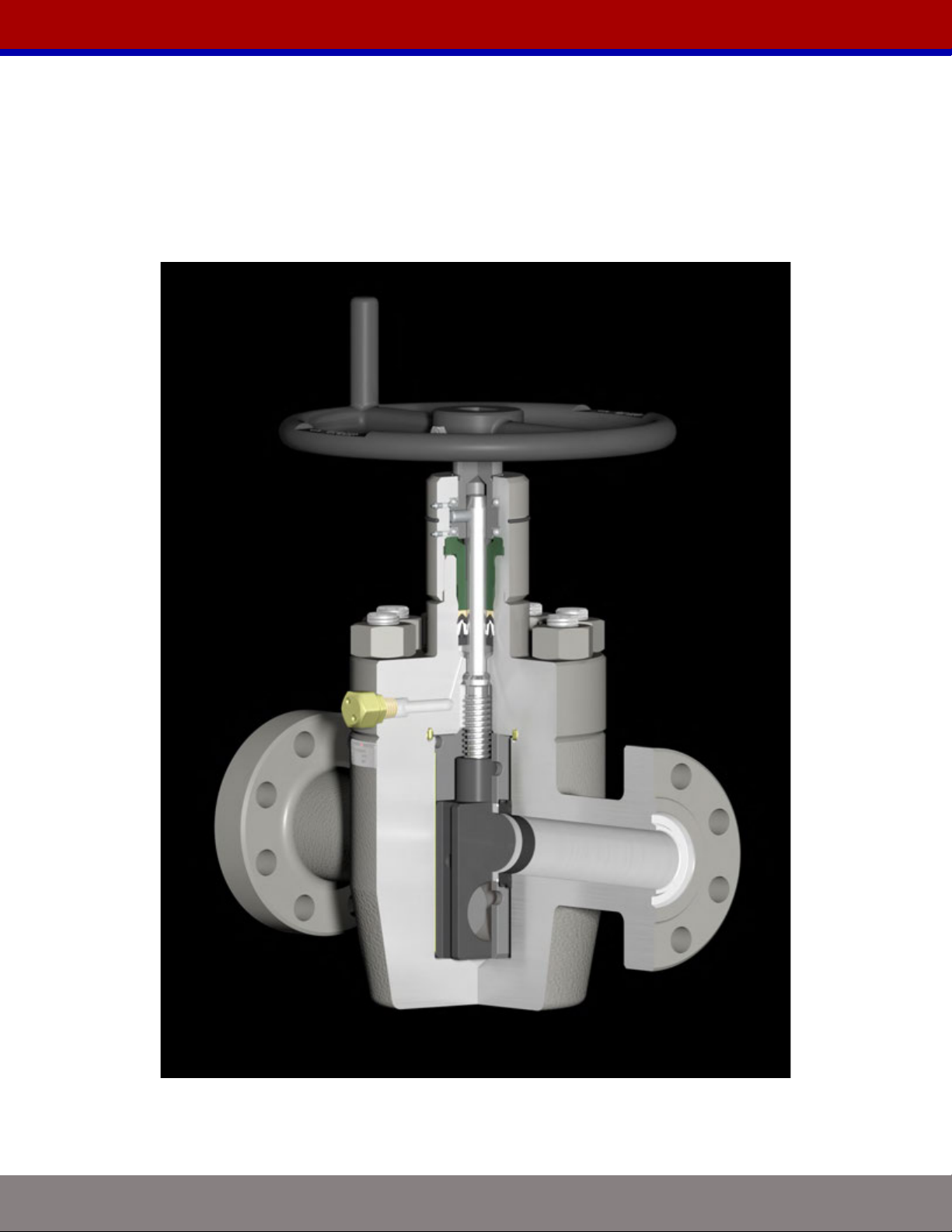
A
B
C
D
E
NT
RJ
TS
BSS
N
WT
HT
FACE TO FACE
VALVE BORE SIZE (NOMINAL)
BORE CENTERLINE TO BOTTOM
BORE CENTERLINE TO TOP
HANDWHEEL DIAMETER
NUMBER OF TURNS
RING JOINT
THREAD SIZE
BONNET STUD SIZE
NUMBER OF STUDS
APPROXIMATE WEIGHT
HANDWHEEL OPERATING TORQUE
DIMENSION TABLE KEY
THREADED GATE VALVES
SIZE WP (PSI) A B C D ENT TS BSS N WT
(LBS)
HT
(FT-LBS)
2 1/16 5K 9 5/8 2 1/16 5 1/2 19 5/8 13 14 2 LP
2 3/8 EU 7/8 8 125 57
2 9/16
3K 10 1/4 2 9/16 6 5/8 20 7/8 16 16 1/2 2 1/2 LP 7/8 8 160 49
5K 10 1/4 2 9/16 6 5/8 20 7/8 16 16 1/2 2 7/8 EU 7/8 8 160 66
3 1/8
3K 11 3/8 3 1/8 7 5/8 23 16 20 3/4 3 LP 1 8 230 65
5K 11 3/8 3 1/8 7 5/8 23 16 20 3/4 3 1/2 EU 1 8 230 90
4 1/16
3K 13 4 1/16 9 5/8 26 5/8 20 24 3/4 4 LP 1 3/8 8 420 67
5K 13 4 1/16 9 5/8 26 5/8 20 24 3/4 4 1/2 EU
4 1/2 LC 1 3/8 8 420 130
FLANGED GATE VALVES
*ALL DIMENSIONS ARE IN INCHES
TECHNICAL DATA M SERIES
ENGINEERED -DESIGNED -VERIFIED -QUALITY ASSURED -CERTIFIED -FIELD PROVEN -CREDIBLE -SUPPORTED
i
PAGE: 3 of 7

MODEL MDS -UNIDIRECTIONAL, EXPANDING GATE, CAST BODY
GATE GUIDE
SEAT
a
GATE
CAST BODY
BONNET
STEM PACKING SET
BEARING RETAINER
HANDWHEEL
gBEARING GREASE FITTING
fPACKING INJECTION FITTING
STEM
PACKING RETAINER
BODY GREASE FITTING
BEARING
BONNET SEAL RING
EXPANDING
d
O-RING
NAME PLATE
STUDS & NUTS
a) Equipped with a non-sealing seat on the upstream side. See engineering note titled “Model MDS (Model M Directional Seal)” for details.
d) See engineering note titled “Expanding Gate Assembly Operation Explained” for details.
f) Stuffi ng box can be repacked via injectable packing while the valve is in service up to the rated working pressure.
g) Valve bonnet equipped with grease port(s) and fi tting(s) for bearing lubrication.
ENGINEERED -DESIGNED -VERIFIED -QUALITY ASSURED -CERTIFIED -FIELD PROVEN -CREDIBLE -SUPPORTED
i
PAGE: 4 of 7
*THE ACTUAL PRODUCT MAY VARY SLIGHTLY FROM SHOWN SCHEMATIC DUE TO ENGINEERING APPROVED VARIATION

MODEL MSG -BIDIRECTIONAL, SLAB GATE, CAST BODY
GATE GUIDE
SEAT
GATE
CAST BODY
BONNET
BEARING RETAINER
HANDWHEEL
gBEARING GREASE FITTING
fPACKING INJECTION FITTING
STEM
PACKING RETAINER
BODY GREASE FITTING
BEARING
BONNET SEAL RING
SLAB
O-RING
NAME PLATE
STUDS & NUTS
DRIVE NUT
f) Stuffi ng box can be repacked via injectable packing while the valve is in service up to the rated working pressure.
g) Valve bonnet equipped with grease port(s) and fi tting(s) for bearing lubrication.
STEM PACKING SET
ENGINEERED -DESIGNED -VERIFIED -QUALITY ASSURED -CERTIFIED -FIELD PROVEN -CREDIBLE -SUPPORTED
i
PAGE: 5 of 7
*THE ACTUAL PRODUCT MAY VARY SLIGHTLY FROM SHOWN SCHEMATIC DUE TO ENGINEERING APPROVED VARIATION

MODEL MRC DS -UNIDIRECTIONAL, EXPANDING GATE, FORGED BODY
GATE GUIDE
SEAT
a
GATE
FORGED BODY
BONNET
BEARING RETAINER
HANDWHEEL
gBEARING GREASE FITTING
fPACKING INJECTION FITTING
STEM
PACKING RETAINER
BODY GREASE FITTING
BEARING
BONNET SEAL RING
EXPANDING
d
O-RING
a) Equipped with a non-sealing seat on the upstream side. See engineering note titled “Model MDS (Model M Directional Seal)” for details.
d) See engineering note titled “Expanding Gate Assembly Operation Explained” for details.
f) Stuffi ng box can be repacked via injectable packing while the valve is in service up to the rated working pressure.
g) Valve bonnet equipped with grease port(s) and fi tting(s) for bearing lubrication.
STEM PACKING SET
ENGINEERED -DESIGNED -VERIFIED -QUALITY ASSURED -CERTIFIED -FIELD PROVEN -CREDIBLE -SUPPORTED
i
PAGE: 6 of 7
*THE ACTUAL PRODUCT MAY VARY SLIGHTLY FROM SHOWN SCHEMATIC DUE TO ENGINEERING APPROVED VARIATION

PROPRIETARY BOOKLET OF VALVEWORKS USA. DO NOT REPRODUCE WITHOUT EXPLICIT PERMISSION.
MODEL FC GATE VALVE
SERVICE AND OPERATION MANUAL
PROPRIETARY BOOKLET OF VALVEWORKS USA. DO NOT REPRODUCE WITHOUT EXPLICIT PERMISSION.

WWW.VALVEWORKSUSA.COM[email protected]
PROPRIETARY BOOKLET OF VALVEWORKS USA. DO NOT REPRODUCE WITHOUT EXPLICIT PERMISSION.
Page 4
APPLICATIONS
Valveworks USA Model FC gate valves can be applied to the following sizes and working
pressures.
APPLICATION OPTIONS AVAILABLE
GATE VALVE SIZE 1-13/16, 2-1/16, 2-9/16,
3-1/8, 3-1/16, 4-1/16
MAXIMUM ALLOWABLE WORKING PRESSURE (MAWP) 3M, 5M, 10M, 15M
TEMPERATURE RANGE -18°C TO 180°C
(0°F TO 350°F)
The Model FC Gate Valves covered in this manual are suitable for performance requirement
levels 1 and 2, PR1 and PR2 respectively.
TEMPERATURE RATING
TEMPERATURE
CLASSIFICATION
OPERATING RANGE
°C (°F)
K -60 82 -75 180
L -46 82 -50 180
N -46 60 -50 140
P -29 82 -20 180
S -18 60 0 140
T -18 82 0 180
U -18 121 0 250
V 2 121 35 250
X -18 180 0 350
TRIM CHART
MATERIAL
CLASS
MINIMUM MATERIAL REQUIREMENTS
BODY, BONNET, END AND OUTLET
CONNECTIONS
PRESSURE-CONTROLLING PARTS,
STEMS, AND MANDREL HANGERS
AA - General Service Carbon or low-alloy steel Carbon or low-alloy steel
BB - General Service Carbon or low-alloy steel Stainless steel
CC - General Service Stainless steel Stainless steel
DD - Sour Service
a
Carbon or low-alloy steel
b
Carbon or low-alloy steel
b
EE - Sour Service
a
Carbon or low-alloy steel
b
Stainless steel
b
FF - Sour Service
a
Stainless steel
b
Stainless steel
b
HH - Sour Service
a
CRAs
b
CRAs
b
a As dened by NACE MR0175.
b
In compliance with NACE MR0175.
As shown by API-6A. For specic details, consult Valveworks USA.
MODEL FC SERVICE AND OPERATION MANUAL

WWW.VALVEWORKSUSA.COM[email protected]
PROPRIETARY BOOKLET OF VALVEWORKS USA. DO NOT REPRODUCE WITHOUT EXPLICIT PERMISSION.
Page 6
MODEL FC - SLAB GATE
2-1/16” 10M
(HANDWHEEL OPERATED)
MODEL FC SERVICE AND OPERATION MANUAL

WWW.VALVEWORKSUSA.COM[email protected]
PROPRIETARY BOOKLET OF VALVEWORKS USA. DO NOT REPRODUCE WITHOUT EXPLICIT PERMISSION.
Page 7
MODEL FC - BILL OF MATERIALS
ITEM DESCRIPTION QTY
1 BODY 1
2 BONNET 1
3 BONNET SEAL RING 1
4 BODY GREASE FITTING 1
5 STUDS AND BOLTS 8
6 BODY BUSHING SEAL 2
7 SEAT 2
8 BODY BUSHING 2
9 SEAT SEAL 2
10 GATE GUIDE 2
11 GATE SLAB 1
12 TORRINTION BEARINGS 2
13 PACKING GLAND 1
14 BEARING CAP 1
15 STEM ADAPTER 1
16 STEM ADAPTER 0-RING 1
17 STEM 1
18 SHEAR PIN 1
19 GREASE ALEMITE FITTING 2
20 HANDWHEEL 1
21 BEARING CAP O-RING 1
22 HANDWHEEL BOLT 1
23 HANDWHEEL NUT 1
24 RETAINING PLATE 2
25 OPTI-SEAL 1
25 BACK-UP RING 2
MODEL FC SERVICE AND OPERATION MANUAL

WWW.VALVEWORKSUSA.COM[email protected]
PROPRIETARY BOOKLET OF VALVEWORKS USA. DO NOT REPRODUCE WITHOUT EXPLICIT PERMISSION.
Page 8
PART NUMBER BREAKDOWN: 290 - A B X Y
“A” MAWP “B” BORE SIZE
5 5,000 PSI 1 1-13/16”
7 10,000 PSI 2 2-1/16”
8 15,000 PSI 33-1/8” (5M)
3-1/16” (10M,15M)
4 4-1/16”
“X” MATERIAL TYPE “Y” COATING
1 4130
0
NONE; PHOSPHATE, MOLY,
STANDARD PAINT/COATING,
POWDER COAT
1A 4140
1B 1040
1C 1018
1D 1020
1E SA285-C
1
NITRIDE QPQ-PHOSPHATE;
EXCEPTION - FC BODY BUSHING -
DO NOT NITRIDE
1F 1026
2 410SS FORGED
2A S42400
3 174SS
3A NITRONIC 50
2HARDFACE-STELLITE #6
SPRAY & FUSE
4 316SS
4A 316/304SS
4B 304SS
3 HARDFACE - TUNGSTEN CARBIDE5 BRONZE
6 INCONEL 718
6A INCONEL 725 4 HARDFACE - COLMONOY #5
6B INCONEL X750
7 MONEL 5 ELECTROLIS NICKEL
8 A487-4D
8A A487-4C 6 WELD ON HARDFACE
8B CA15
8C CF8M 7 ZINC PLATE
8D CF3M 8 XYLAN COATING
8E CA6NM 9 (4130) INCONEL 625 CLAD
9 STELLITE #6
9A PLASTIC 9A (4130)SS-316-RING GROOVE
9B STELLITE #3
The last two digits in the part number vary with “X” Material Type and “Y” Coating. The table
below gives the different available material types and coatings. Please refer to the valve tag to
know the material type and coating on the valve parts.
MODEL FC SERVICE AND OPERATION MANUAL

WWW.VALVEWORKSUSA.COM[email protected]
PROPRIETARY BOOKLET OF VALVEWORKS USA. DO NOT REPRODUCE WITHOUT EXPLICIT PERMISSION.
Page 9
DISASSEMBLING THE VALVE
1. Operate the valve to insure no
trapped pressure is present.
Leave the gate set partially open.
2. Unscrew and remove the
Handwheel Nut using a wrench.
Remove the Handwheel Bolt and the
Handwheel.
5. Remove the Bonnet Sub-Assembly
4. Replace the Handwheel and rotate
it in the counter-clockwise direction.
This will separate the Gate from the
Stem.
6. Remove the Gate.
8. Remove the Retainer Plates and
Seats.
7. Remove the Gate Guides. 9. Remove the Body Bushings.
3. Unscrew and remove all Bonnet
Bolts using an impact wrench.
MODEL FC SERVICE AND OPERATION MANUAL

WWW.VALVEWORKSUSA.COM[email protected]
PROPRIETARY BOOKLET OF VALVEWORKS USA. DO NOT REPRODUCE WITHOUT EXPLICIT PERMISSION.
Page 10
DISASSEMBLING THE BONNET SUB-ASSEMBLY
2. Remove the Shear Pin from the
Stem Adapter.
1. Unscrew and remove the Bearing
Cap. 3. Remove the Stem Adapter.
5.Remove the Stem.
4. Unscrew and remove the
Packing Gland.
6. Remove the Stem Packing with a
pick. Avoid scratching the internal
wall of the Bonnet during removal of
the packing.
NOTE:
Replace non-metalic seals while assembling the valve.
MODEL FC SERVICE AND OPERATION MANUAL

WWW.VALVEWORKSUSA.COM[email protected]
PROPRIETARY BOOKLET OF VALVEWORKS USA. DO NOT REPRODUCE WITHOUT EXPLICIT PERMISSION.
Page 14
1. Lightly oil ring groove.
Grease and insert a ring joint
into the body ange.
5. Tighten the hex nuts on the test
ange side with an impact wrench
until they are tight.
4. Screw a hex nut on the vacant side
of each stud until all of the studs
have a nut connecting the test ange
to the body ange.
6. A nished ange shown.
8. Remove the grease tting cap
from one test ange and attach a
pressure release tool.
7. Repeat steps 1-5 for the opposite
ange.
9. Remove the grease tting cap
from the opposite test ange and
attach the ow line.
TEST PROCEDURE
2. Be sure that the test ange has
a tightened grease tting, all of its
studs, and a nut on each with all of
the nuts on the grease tting side.
3. Align the test ange studs with the
body ange holes. Then, push the
test anges, its studs, and their hex
nuts onto the body ange.
MODEL FC SERVICE AND OPERATION MANUAL

WWW.VALVEWORKSUSA.COM[email protected]
PROPRIETARY BOOKLET OF VALVEWORKS USA. DO NOT REPRODUCE WITHOUT EXPLICIT PERMISSION.
Page 15
2. After removing the body ange
hex nuts, you can remove the test
ange, its studs, and their hex nuts.
1. While holding the hex nuts on the
body ange, loosen each of the test
ange hex nuts.
3. Pass a drift mandrel through the
valve bore after the valve has been
assembled, operated, and pressure
tested.
4. Remove the bonnet grease tting cap, and attach a ow line from the grease pump to the bonnet grease tting.
Grease until any remaining water from testing drains from the valve.
HYDROSTATIC SEAT TEST
• With the valve closed, apply the rated working pressure.
• Hold and monitor at that pressure for at least (3) minutes.
• Open the valve, and bleed off the pressure until it’s reduced to zero. Then, close the valve
and the pressure release tool.
• Repeat the steps above.
Switch the sides of your ow and pressure release connections, bleed off the new pressure
release side, and repeat steps above to perform a seat test on the new ow side.
The valve is acceptable if no leakage is visible during the holding period.
MODEL FC SERVICE AND OPERATION MANUAL

WWW.VALVEWORKSUSA.COM[email protected]
PROPRIETARY BOOKLET OF VALVEWORKS USA. DO NOT REPRODUCE WITHOUT EXPLICIT PERMISSION.
Page 16
2. Be sure the Alemite ttings are on
and tight.
1. Be sure the bonnet grease tting
cap is on and tight.
3. Be sure the Hand wheel Nut is
tight.
4. The gate must be fully open (shown) or fully closed.
VISUAL INSPECTION
4. Torque the service ange
hex nuts with a certied
torque gun or wrench until tight.
3. Screw a hex nut on both
sides of each stud by hand.
5. A nished ange should appear as
shown.
2. Align the service ange holes with the body ange
holes. Push a stud through each aligned
hole until there is a stud through each hole.
1. Lightly oil ring groove.
Grease and insert a ring joint into the body ange.
FIELD HOOK-UP INSTRUCTIONS
MODEL FC SERVICE AND OPERATION MANUAL

WWW.VALVEWORKSUSA.COM[email protected]
PROPRIETARY BOOKLET OF VALVEWORKS USA. DO NOT REPRODUCE WITHOUT EXPLICIT PERMISSION.
Page 17
CAUTION:
Never remove packing gland while valve is under pressure unless the pressure has been isolated.
1. Unscrew and remove the
Handwheel Nut using a wrench.
2. Remove the Handwheel Bolt and
the Handwheel.
REPLACING BROKEN SHEAR PIN (WHILE IN SERVICE)
3. Unscrew and remove the Bearing
Cap.
Note:
a) If Bearing Cap tries to remove the packing gland hit the stem adapter rmly to break any gunk build up.
b) If the Bearing Cap will not remove without unthreading the packing gland, then pressure must be removed
from the valve or the valve MUST be back seated.
c) Once Bearing Cap is free or Valve is back seated go to step 4.
4. Once Bearing Cap is removed,
replace damaged shear pin.
5. Retighten packing gland with pipe
wrench (~100 ft*lbf)
Note: Debur with sandpaper if needed.
6. Retighten bearing cap with pipe
wrench (~100 ft*lbf)
Note: Debur with sandpaper if needed.
MODEL FC SERVICE AND OPERATION MANUAL

WWW.VALVEWORKSUSA.COM[email protected]
PROPRIETARY BOOKLET OF VALVEWORKS USA. DO NOT REPRODUCE WITHOUT EXPLICIT PERMISSION.
Page 18
WARNING:
1. The backseat is only intended to be used in an emergency situation to stop packing
leakage.
2. One of the features of the back seat is to change the stem packing under pressure on well,
even though it is not promoted. It is always recommended that the valve be removed from
service before packing is changed unless an emergency. If the packing has to be changed
while under pressure, a second pressure barrier needs to be used to help isolate the
pressure.
3. By backseating the valve it is possible the gate will not seal the bore line.
2. Loosen the bearing cap using a
pipe wrench.
(Approximately 3 1/2 - 4 turns)
1. Turn the handwheel counter-
clockwise until the gate is in the
open position.
(In case of Direct Operating gate)
3. Turn the handwheel clockwise
until the gate is in the closed
position.
BACK SEATING PROCEDURE
4. Over run the closed position such
that the gate hits the bottom and
rises the stem; which jams the back
seat area.
MODEL FC SERVICE AND OPERATION MANUAL

WWW.VALVEWORKSUSA.COM[email protected]
PROPRIETARY BOOKLET OF VALVEWORKS USA. DO NOT REPRODUCE WITHOUT EXPLICIT PERMISSION.
Page 21
MODEL FC SERVICE AND OPERATION MANUAL
A
B
C
D
E
NT
WT
FLANGE TO FLANGE
VALVE BORE SIZE
BORE CENTERLINE TO BOTTOM
BORE CENTERLINE TO TOP
HANDWHEEL DIAMETER
NUMBER OF TURNS
APPROXIMATE WEIGHT
DIMENSION TABLE KEY
E
D
A
C
B
SIZE WP (PSI) A B C D E NT WT
1 13/16 10K 18 1/4 1 13/16 5 13/16 18 13/16 16 11 3/4 270
15K 18 1 13/16 6 13/16 18 13/16 16 11 3/4 275
2 1/16
3K/5K 14 5/8 2 1/16 5 7/8 18 7/8 14 12 189
10K 20 1/2 2 1/16 5 13/16 18 13/16 16 12 1/2 275
15K 19 2 1/16 6 1/8 18 13/16 16 12 1/2 350
2 9/16
3K/5K 16 5/8 2 9/16 6 5/16 19 1/2 16 16 1/4 275
10K 22 1/4 2 9/16 6 7/8 19 5/8 20 16 485
15K 21 2 9/16 7 13/16 22 7/8 20 15 1/2 520
3 1/8 3K 17 1/8 3 1/8 7 13/16 20 1/2 16 17 1/2 337
5K 18 5/8 3 1/8 7 9/16 20 1/2 16 17 1/2 355
3 1/16 10K 24 3/8 3 1/16 8 1/8 22 23 17 1/2 550
15K 23 9/16 3 1/16 9 1/8 25 5/8 23 15 1/2 914
4 1/16
3K 20 1/8 4 1/16 9 5/16 22 20 23 1/4 498
5K 21 5/8 4 1/16 9 13/16 22 20 23 1/4 550
10K 26 3/8 4 1/16 10 1/8 28 3/4 24 23 1/4 950

MODEL MRC SG -BIDIRECTIONAL, SLAB GATE, FORGED BODY
GATE GUIDE
SEAT
GATE
FORGED BODY
BONNET
BEARING RETAINER
HANDWHEEL
gBEARING GREASE FITTING
fPACKING INJECTION FITTING
STEM
PACKING RETAINER
BODY GREASE FITTING
BEARING
BONNET SEAL RING
SLAB
O-RING
f) Stuffi ng box can be repacked via injectable packing while the valve is in service up to the rated working pressure.
g) Valve bonnet equipped with grease port(s) and fi tting(s) for bearing lubrication.
STEM PACKING SET
DRIVE NUT
ENGINEERED -DESIGNED -VERIFIED -QUALITY ASSURED -CERTIFIED -FIELD PROVEN -CREDIBLE -SUPPORTED
i
PAGE: 7 of 7
*THE ACTUAL PRODUCT MAY VARY SLIGHTLY FROM SHOWN SCHEMATIC DUE TO ENGINEERING APPROVED VARIATION
This manual suits for next models
4
Table of contents
Popular Industrial Equipment manuals by other brands

Poly-Clip System
Poly-Clip System FCA 3430 Maintenance and spare parts

Nexen
Nexen WEB CONTROL TC250 user manual

Trinity Highway
Trinity Highway QuadGuard Elite M10 Wide Product Description Assembly Manual

Grundfos
Grundfos Oxiperm Pro OCD-162-5 Installation and operating instructions

Siemens
Siemens Simatic 6ES7 157-0AD81-0 A0 Series manual

Rockwell Automation
Rockwell Automation THR Triguard SC300E quick start guide