V&A VA41 User manual

Contents
TITLE PAGE
1. GENERAL INSTRUCTIONS ………………………………………………… 1
1.1 Precaution safety measures ………………………………………………… 1
1.1.1 Preliminary ………………………………………………… 1
1.1.2 During use ………………………………………………… 3
1.2 Symbols ………………………………………………… 4
1.3 Instructions ………………………………………………… 4
2. DESCRIPTION ………………………………………………… 6
2.1 Instrument Familiarization ………………………………………………… 6
2.2 LCD Display ………………………………………………… 7
2.3 Key pad ………………………………………………… 9
3. FUNCTION DESCRIPTION ………………………………………………… 10
3.1 General Functions ………………………………………………… 10
3.1.1 Auto scan mode ………………………………………………… 10
3.1.2 DATA HOLD mode ………………………………………………… 11
3.1.3 Manual ranging and Auto range mode ………………………………………………… 11
3.1.4 True RMS measurement ………………………………………………… 12
3.1.5 Auto power off setting ………………………………………………… 12
3.2 Measurement Functions ………………………………………………… 13
3.2.1 AC and DC Voltage measurement ………………………………………………… 13
3.2.2 Non-contact electric field detector (EF mode) ………………………………………………… 14
3.2.3 Resistance measurement ………………………………………………… 15

TITLE PAGE
3.2.4 Continuity Check ………………………………………………… 16
3.2.5 Diode Test ………………………………………………… 17
3.2.6 Capacitance measurement ………………………………………………… 18
3.2.7 Current measurement ………………………………………………… 19
4. TECHNICAL SPECIFICATIONS ………………………………………………… 20
4.1 General specifications.. ………………………………………………… 20
4.2 Measurement specifications ………………………………………………… 20
4.2.1 AC Voltage ………………………………………………… 21
4.2.2 DC Voltage ………………………………………………… 21
4.2.3 Resistance ………………………………………………… 22
4.2.4 Continuity Check ………………………………………………… 22
4.2.5 Diode Test ………………………………………………… 22
4.2.6 Capacitance ………………………………………………… 22
4.2.7 Current ………………………………………………… 23
4.2.8 Linear frequency ………………………………………………… 23
5. MAINTENANCE ………………………………………………… 24
5.1 General maintenance ………………………………………………… 24
5.2 Fuse replacement ………………………………………………… 24
5.3 Battery replacement ………………………………………………… 25
6. ACCESSORIES ………………………………………………… 25

6000 COUNTS DIGITAL MULTIMETER
USER'S MANUAL
1
1. GENERAL INSTRUCTIONS
This instrument complies with IEC 61010-1:2001, CAT 1000V and CAT Ⅵ600V overvoltage standards. See
Specifications.
To get the best service from this instrument, read carefully this user's manual and respect the detailed safety
precautions.
International symbols used on the Meter and in this manual are explained in chapter 1.2.
1.1 Precautions safety measures
1.1.1 Preliminary
*As the possibilities of high transient overvoltages occurred in today’s power systems increase, more stringent
safety standards are set for the electrical test equipment. Transients on electrical systems(power grid, feeder or
branch circuits) will trigger a series of incidents that may result in serious personal injury. To protect you against
transients, safty must be built into the test equipment.

6000 COUNTS DIGITAL MULTIMETER
USER'S MANUAL
2
Overvoltage
cate
g
or
y
In brief Examples
CATⅠElectronic
• Protected electronic equipment.
• Equipment connected to (source) circuits in which measures are taken to
limit transient overvoltages to an appropriately low level.
• Any high-voltage, low-energy source derived from a highwinding
resistance transformer, such as the high-voltage section of a copier.
CATⅡ
Single-phase
receptacle
connected loads
• Appliance, portable tools, and other household and similar loads.
• Outlet and long branch circuits.
• Outlets at more than 10 meters (30 feet) from CAT III source.
• Outlets at more that 20 meters (60 feet) from CAT IV source.
CAT Ⅲ
Three-phase
distribution,
including
single-phase
commercial lighting
• Equipment in fixed installations, such as switchgear and polyphase
motors.
• Bus and feeder in industrial plants.
• Feeders and short branch circuits, distribution panel devices.
• Lighting systems in larger buildings.
• Appliance outlets with short connections to service entrance.
CAT Ⅵ
Three-phase at
utility connection,
any outdoor
conductors
• Refers to the “origin of installation”; i.e., where low-voltage connection is
made to utility power.
• Electricity meters, primary overcurrent protection equipment.
• Outside and service entrance, service drop from pole to building, run
between meter and panel.
• Overhead line to detached building, underground line to well pump.
*When using this Multimeter, the user must observe all normal safety rules concerning:
―protection against the dangers of electric current.
―protection of the Multimeter against misuse.
*For your own safety, only use the test probes supplied with the instrument. Before use, check that they are in good
condition.

6000 COUNTS DIGITAL MULTIMETER
USER'S MANUAL
3
1.1.2 During use
*If the meter is used near noise generating equipment, be aware that display may become unstable or indicate large
errors.
*Do not use the meter or test leads if they look damaged.
*Use the meter only as specified in this manual; otherwise, the protection provided by the meter may be impaired.
*Use extreme caution when working around bare conductors or bus bars.
*Do not operate the meter around explosive gas, vapor, or dust.
*Verify a Meter's operation by measuring a known voltage. Do not use the Meter if it operates abnormally. Protection
may be impaired. When in doubt, have the Meter serviced.
*Uses the proper terminals, function, and range for your measurements.
*When the range of the value to be measured is unknown, check that the range initially set on the multimeter is the
highest possible or, wherever possible, choose the autoranging mode.
*To avoid damages to the instrument, do not exceed the maximum limits of the input values shown in the technical
specification tables.
*When the multimeter is linked to measurement circuits, do not touch unused terminals.
*Caution when working with voltages above 60Vdc or 30Vac rms. Such voltages pose a shock hazard.
*When using the probes, keep your fingers behind the finger guards.
*When making connections, connect the common test lead before connecting the live test lead; when disconnecting,
disconnect the live test lead before disconnecting the common test lead.
*Before changing functions, disconnect the test leads from the circuit under test.
*For all dc functions, including manual or auto-ranging, to avoid the risk of shock due to possible improper reading,
verify the presence of any ac voltages by first using the ac function. Then select a dc voltage range equal to or
greater than the ac range.
*Disconnect circuits power and discharge all high-voltage capacitors before testing resistance, continuity, diodes, or
capacitance.
*Never perform resistance or continuity measurements on live circuits.
*Before measuring current, check the meter's fuse and turn off power to the circuit before connecting the meter to
the circuit.

6000 COUNTS DIGITAL MULTIMETER
USER'S MANUAL
4
*In TV repair work, or when carrying out measurements on power switching circuits, remember that high amplitude
voltage pulses at the test points can damage the multimeter. Use of a TV filter will attenuate any such pulses.
*Use just one 6F22 battery, properly installed in the Meter's battery case, to power the Meter.
*Replace the battery as soon as the battery indicator ( ) appears. With a low battery, the Meter might produce false
readings that can lead to electric shock and personal injury.
*Do not measure voltages above 1000V in Category III, or 600V in Category Ⅳinstallations.
*Do not operate the Meter with the case (or part of the case) removed.
1.2 Symbols:
Symbols used in this manual and on the instrument:
Caution:refer to the instruction manual. Incorrect use may result in damage to the
device or its components.
~ AC (Alternating Current)
DC (Direct Current)
AC or DC
Earth ground
Double insulated
Fuse
Conforms to European Union directives
1.3 Instructions
*Remove test leads from the Meter before opening the Meter case or battery cover.
*When servicing the Meter, use only specified replacement parts.
*Before opening up the instrument, always disconnect from all sources of electric current and make sure you are not
charged with static electricity, which may destroy internal components.

6000 COUNTS DIGITAL MULTIMETER
USER'S MANUAL
5
*Any adjustment, maintenance or repair work carried out on the meter while it is live should be carried out only by
appropriately qualified personnel, after having taken into account the instructions in this present manual.
*A "qualified person" is someone who is familiar with the installation, construction and operation of the equipment
and the hazards involved. He is trained and authorized to energize and de-energize circuits and equipment in
accordance with established practices.
*When the instrument is opened up, remember that some internal capacitors can retain a dangerous potential even
after the instrument is switched off.
*If any faults or abnormalities are observed, take the instrument out of service and ensure that it cannot be used
until it has been checked out.
*If the meter is not going to be used for a long time, take out the battery and do not store the meter in high
temperature or high humidity environment.
6000 COUNTS DIGITAL MULTIMETER
USER'S MANUAL
6
2. DESCRIPTION
2.1 Instrument Familiarization
COM
A
V
mA
uA
A
mA
uA
OFF
EF
VOLT
A
U
T
O
S
C
A
N
1
2
3
4
5
67
8
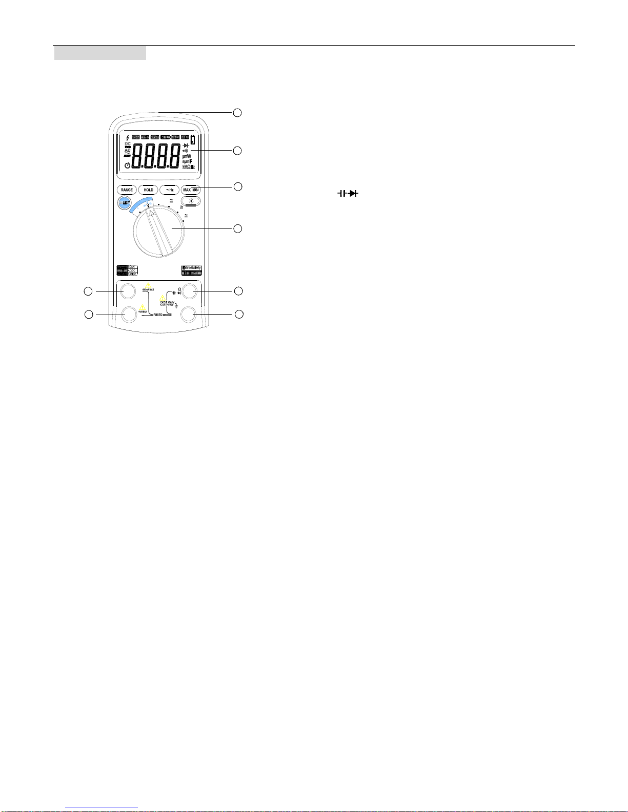
Figure 2-1
The front panel is shown as in Figure 2-1,
explanation being as follows:
○,1 LCD display
Used for displaying the measuring results and various
symbols.
○,2 Keypad
Measurement function keys.
○,3 Rotary switch
Used for selecting measurement functions.
○,4 VΩ
Terminal receiving the red test lead for voltage,
resistance, capacitance, diode and continuity
measurements.
○,5 uA/mA
Terminal receiving the red test lead for μA, mA
measurements.
○,6 A
Terminal receiving the red test lead for 6A,10A
measurements.
○,7 COM
Terminal receiving the black test lead as a common
reference.
○,8 EF-detection area.

6000 COUNTS DIGITAL MULTIMETER
USER'S MANUAL
7
2.2 LCD Display
Figure 2-2
1
2
3
5
4
678910 11
12
13
14
15
17
16

6000 COUNTS DIGITAL MULTIMETER
USER'S MANUAL
8
LCD screen is shown as in Figure 2-2, with its every symbol’s meaning shown as in the Table 1:
No. Symbol Meaning
1 Indicator for auto power off
2 Indicates negative readings
3 Indicator for AC voltage or current
4 Indicator for DC voltage or current
5 Unsafe voltage. voltage≥30V, or voltage overload(OL)
6 SCAN When auto scan mode is selected
7 AUTO The meter is in the Autorange mode in which the meter automatically selects the
range with the best resolution.
8 MANU The meter is in the Manual Range mode in which the user selects the range.
9 HOLD When HOLD function is enabled. When delay-hold is selected, the HOLD symbol
will be blinking for 6 seconds.
10 MAX Display maximum data
11 MIN Display minimum data
12 Low battery indication (Note: When this symbol appears, it means that the battery
needs to be replaced.
)
13 The meter is in Diode Test mode.
14 The meter is in Continuity Check mode.
15 μmVA,nμmF,KMΩHz Measurement units
16 This symbol means that the input is too large for the selected range.
17 EF The meter is in non-contact electric field detector mode.
This manual suits for next models
1
Table of contents
Other V&A Multimeter manuals


Popular Multimeter manuals by other brands


Gossen MetraWatt
Gossen MetraWatt METRAmax 6 operating instructions

PeakTech
PeakTech 4000 Procedure of calibration

YOKOGAWA
YOKOGAWA 90050B user manual

Gossen MetraWatt
Gossen MetraWatt METRALINE DMM16 operating instructions

Fluke
Fluke 8846A Programmer's manual

Tempo Communications
Tempo Communications MM200 instruction manual


