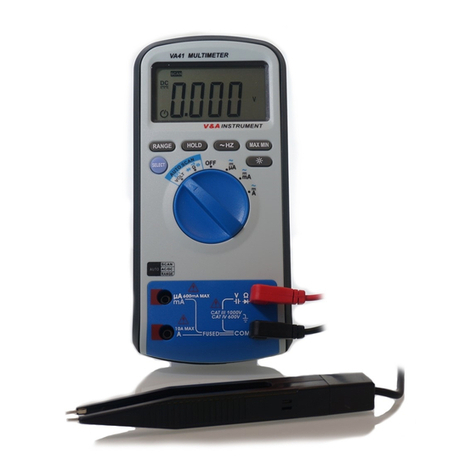
V&A 8320 User manual

Pocket Multimeter M320
USER’S MANUAL
SAFETY INFORMATION
Measurement category II is for the measurements performed on
circuits directly connected to the low voltage installation. This meter has
been designed according to IEC-1010 concerning electronic measuring
instruments with an overvoltage category (CAT II) and pollution degree
2.Follow all safety and operating instructions to ensure the meter is
used safely and is kept in good condition.
With proper use and care, your digital multimeter will give you years
of satisfactory service.
DURING USE
Never exceed the protection limit indicated in the specifications for
each range of measurement.
Never use the meter to measure voltages that might exceed 600V
above earth ground in category II installations.
Always be careful when working with voltages above 60V dc or 30V
ac rms. Keep fingers behind the probe barriers while measuring.
Do not perform resistance measurements on live circuits.
Inspect test leads and probes for cracks, breaks or crazes in the
insulation before using the meter.
SAFETY SYMBOL
Caution:refer to the instruction manual. Incorrect use
may result in damage to the device or its components.

~
AC (Alternating Current)
DC (Direct Current)
AC or DC
Earth ground
Double insulated
Fuse
Conforms to European Union directives
MAINTENACE
Before opening case, always disconnect test leads from all
energized circuits.
For continuous protection against fire, replace fuse only with ratings:
F 500mA /250V 520 (Quick Acting).
Never use the meter unless the back cover is in place and fastened
completely.
Do not use abrasives or solvents on the meter. To clean it use only a
damp cloth and mild detergent.
GENERAL DESCRIPTION
This compact digital multimeter is designed to measure AC and DC
voltage, AC and DC current, Resistance, Capacitance, Diode and to
perform audible continuity checks with accuracy and ease.
Small and light weight, with a carrying case and test leads wound on
its body, this instrument will provide you years of satisfactory service.
SPECIFICATION
Accuracy is specified for one year after calibration, at operating
temperatures of 18℃to 28℃, with relative humidity at 0% to 75%.
Accuracy specifications take the form of: ±(% of Reading + Number of
Least Significant Digits)
Voltage
Function
Range
Resolution
Accuracy
DC Millivolt.
mV
400mV
0.1mV
±(1.0% of rdg
+10 digits)
DC Voltage
V
4V
1mV
±(0.5% of rdg +3
digits)
40V
10mV
400V
100mV
600V
1V
AC Voltage1,2
V~
4V
1mV
±(1.0% of rdg + 3
digits)
40V
10mV
400V
100mV
600V
1V
1. Frequency Range: 40Hz~500Hz
2. Response: Average, calibrated in rms of sine wave
3. Overload Protection: 600V dc or 600V ac rms.
Current
Function
Range
Resolution
Accuracy
DC Current
mA
40mA
0.01mA
±(1.5% of rdg+3
digits)
400mA
0.1mA
AC Current
mA ~
40mA
0.01mA
±(1.5% of rdg+3
digits)
400mA
0.1mA
Overload protection:
F 500mA/250V fuse for mA range.
Maximum input current: 400mA dc or 400mA ac rms for mA range.
Resistance
Function
Range
Resolution
Accuracy
1<<<
>>>2

Resistance
400.0
0.1
±(0.5% of rdg+3 digits)
4.000k
1
±(0.5% of rdg+2 digits)
40.00k
10
400.0k
100
4.000M
1k
40.00M
10k
±(1.5% of rdg+3 digits)
Overload protection: 600V dc or 600V ac rms.
Capacitance
Function
Range
Resolution
Accuracy
Capacitance
50nF
10pF
<10nF:±[5.0% of (rdg-50
digits)+10 digits]
±(3.0% of rdg+10 digits)
500nF
100pF
±(3.0% of rdg+5 digits)
5F
1nF
50F
10nF
100F
100nF
Overload protection: 600V dc or 600V ac rms.
Diode Test
Function
Range
Resolution
Accuracy
Diode Test
1 V
0.001V
1.0% uncertainty
Overload protection: 600V dc or 600V ac rms.
Test Condition: Forward DC current approximately 1mA. Reversed DC
voltage approximately 1.5V.
Continuity Check
Function
Range
Resolution
Description
Continuntiy Test
400
0.1
Continuity beeper≤
50
Overload protection: 600V dc or 600V ac rms.
Test Condition: Open circuit voltage: approx. 0.5V
WITH AUTO POWER OFF FUNCTION
GENERAL SPECIFICATIONS
Environment conditions:
600V CAT. II
Pollution degree: 2
Altitude < 2000m
Operating temperature: 0~40℃(32℉~122℉)
Storage temperature: -10~60 ℃(14℉~140℉)
MAX. Voltage between terminals and earth ground: 600V AC rms or
600V DC.
Fuse Protection: F 500mA/250V 520.
Sample Rate: 3 times/sec for digital data.
Display: 3999 LCD display. Automatic indication of functions and
symbols.
Range selection: automatic.
Over Range indication: LCD will display "OL".
Low battery indication: The "BATT" is displayed when the battery is
under the proper operation range.
Polarity indication: "" displayed automatically.
Power source: 3V
Battery type: SR44.
Dimensions: 120(L)70(W)18(H) mm.
Weight: 110g. Approx. (battery included).
3<<<
5<<<
>>>4

OPERATING INSTRUCTION
Voltage Measurement
1. Set rotary switch to the V range.
2. Press the SELECT key to select DCV or ACV measuring mode.
3. Connect the black and red test leads to the circuit being measured
4. Read the displayed value. The polarity of red test lead connection
will be indicated when making a DCV measurement.
Current Measurement
1. Turn off power to the circuit. Discharge all high voltage capacitors.
2. Set the rotary switch to the mA range.
3. Press the SELECT key to select DCA or ACA measuring mode.
4. Break the circuit path to be tested.
Touch the black probe to the more negative side of the break; touch
the red probe to the more positive side of the break. (Reversing the
leads will give a negative reading, but will not damage the Meter.)
6. Turn on power to the circuit; then read the display.
7. Turn off power to the circuit and discharge all high voltage capacitors.
Remove the Meter and restore the circuit to normal operation.
Capacitance Measurement
1. Set the rotary switch to range.
2. Connect the test leads to the capacitor being measured and read
the displayed value.
Resistance Measurement
1. Set the rotary switch to range.
2. Connect the test leads to the circuit or resistor being measured and
read the displayed value.
Diode Test
1. Set the rotary switch to range.
2. For forward-bias readings on any semiconductor component, place
the red test lead on the component's anode and place the black test
lead on the component's cathode.
3. The meter will show the approx. forward voltage of the diode
Audible Continuity Test
1. Set the rotary switch to range.
2. Connect the test leads to the resistance in the circuit being
measured.
3. When the test lead to the circuit is below 50, a continuous beeping
will indicate it.
KEY FUNCTION
Hold Key
Data Hold mode makes the meter stop updating the display. Enabling
Data Hold function in auto range mode makes the meter switch to
Manual ranging mode, but the full-scale range remains the same. Data
Hold function can be cancelled by changing the measurement mode,
pressing RANGE key, or push HOLD key again.
To enter and exit the Data Hold mode:
1. Press HOLD key (short press). Fixes the display on the current value,
DH is displayed.
2. Asecond short press returns the meter to normal mode.
Select Key
1. Switches between dc and ac voltage or current.
2. Disables automatic power-off feature.
BATTERY SAVER

The Meter enters the "sleep mode" and blanks the display if the Meter is
on but not used for 30 minutes.
Press the HOLD key or rotate the rotary switch to wake the meter up.
To disable the Sleep mode, hold down the SELECT function key while
turning the meter on.
BEEPER INDICATION
When press the function key and if it is valid, a beep will be emitted. The
buzzer will sound five times one minute before auto power off. And a
long sound to show the auto power off. In the continuity measuring
status, if the resistance is smaller than 50Ω,the buzzer will sound.
BATTERY & FUSE REPLACEMENT
To replace the Meter's battery:
If the sign "BATT" appears on the LCD display, it indicates that the
battery should be replaced. Remove the screw on the back cover and
open the battery case. Replace the exhausted batteries with two new
1.5V batteries of the same type (SR44).
To replace the Meter's fuse:
Fuse rarely need replacement and blow almost always as a result of
operator’s error. Open the case and replace the blown fuse with the
same rating specified: F 500mA /250V 520.
WARNING!
Before attempting to open the case, always be sure that test leads have
been disconnected from measurement circuits. Close case and tighten
screws completely before using the meter to avoid electrical shock
hazard.
ACCESSORIES
Battery 1.5V (SR44) 2
Carrying Case 1
Operating manual 1
WLS040
>>>6
7<<<
This manual suits for next models
1
Table of contents
Other V&A Multimeter manuals