Vanderbilt SPCV310 User manual

SPCV310
Audio Satellite (en)
Audio-Satellit (de)
Satélite de audio (es)
Satellites audio (fr)
Satellite audio (it)
Audio Satelliet (nl)
Ljudsatellit (sv)
STEP: A6V10397957, Edition: 01.10.2015
1
2
3

English –Installation instruction
ATTENTION: Before starting to install and work with this device, please
read the Safety Instructions.
RISK OF DAMAGE TO THE DEVICE:
Use the device only indoors and in dry environments.
Do not expose it to dripping or splashing water.
Do not let the contact areas of the board get dusty and do not touch
them with your bare hands.
EC Declaration of Conformity
Hereby, Vanderbilt International (IRL) Ltd declares that this equipment type is in
compliance with all relevant EU Directives for CE marking. From 20/04/2016 it is in
compliance with Directive 2014/30/EU (Electromagnetic Compatibility Directive).
The full text of the EU declaration of conformity is available at
http://pcd.vanderbiltindustries.com/doc/SPC
Introduction to the SPCV310
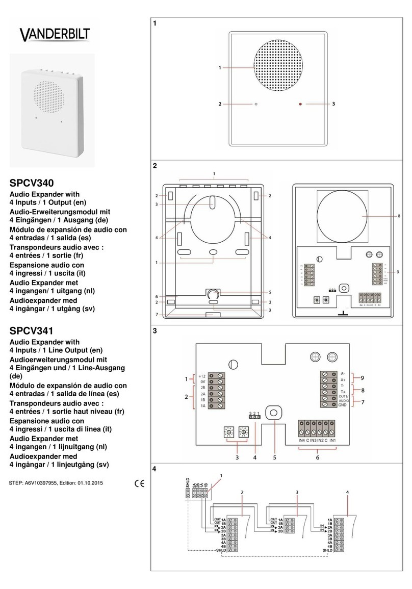
The SPCV310 Audio Satellite is used for pre- / post-event audio recording and live
audio (listen/talk). The device includes an integrated microphone and speaker.
The SPCV310 is a satellite device which must be connected to an audio
expander module (SPCV340/341/440).
Fig. 1 External Casing
1
Loudspeaker
2
Microphone
3
LED
Opening the Housing
1. Use a screwdriver to press the locking tab (Fig. 2, item 7) to release the lock.
2. Lift the cover and push it upwards.
Product Overview
Fig. 2 Back Cover
1
Cable knockouts
2
45°-mounting knockouts
3
Flat-mounting knockouts
4
Cable-tie knockouts
5
Tamper-spring holder
6
Tamper bracket
7
Slot for locking tab
Fig. 2 Inside Front Cover
8
Loudspeaker
9
Audio Satellite PCB
Fig. 3 Audio Satellite PCB
1
Loudspeaker volume control
2
Microphone sensitivity control
3
Tamper switch
4
Free terminals
5
Tamper output
6
Audio connections
7
LED
8
LED Jumper. See LED Functionality for more information.
Mounting Instructions
To ensure good acoustics, please note the following points:
Mount 2 to 3 m above floor level.
Maintain adequate distance from noise sources (ventilation openings, fans
etc.).
Direct towards the centre of the space to be monitored.
Do not mount on vibrating surfaces.
The housing can be mounted flat, or at a 45° angle. Always use two mounting
points which are directly above one another.
You must always use one of the attachment points on the tamper
bracket (Fig. 2, item 6).
Wiring the Satellites
Tamper wiring between the audio expander and satellites must be done in series,
so that a disconnect at any point in the loop will be detected by the expander.
Audio wiring between the audio expander and satellites must be done in parallel.
All the A+ pins must be connected together, and likewise all the A- pins. A twisted
core pair, at least 0.6 mm in diameter, is recommended.
Note that the series connection for tamper makes use of the NC terminal. The
audio is connected in parallel.
Tamper cabling to SPCV340/341: Connect the tamper signals to an Input and 'C'
or use the T+/T- inputs, depending on the configuration of the SPCV340/341.
Tamper cabling to SPCV440: Connect the tamper signals to an Input and GND.
Note: Maximum of 200 m between devices. The following cable types are
recommended:
IYSTY 2 x 2 x 0.6 mm (min.)
UTP cat 5, solid core
Belden 9829
LED Functionality
In normal mode, the LED is on to indicate that the microphone is being used for
live streaming.
LED Jumper
See Fig. 3, item 8. The LED jumper controls the LED state. It has the following
options:
Covered —LED on while microphone is active, and off while speaker is active.
Not covered —LED is inactive. (Default)
Closing the Housing
1. Hook the top of the cover into the base.
2. Push downward to engage the lug with the corresponding recess.
3. Ensure the tamper spring fits in the spring holder (Fig. 2, item 5).
Technical Data
LED indicators
1 (red)
Speaker
5 W, 16 Ω
Microphone
Foil electret condenser microphone with
preamplifier
Tamper contact
Front/back tamper switch
Operating voltage
Through audio +5V DC
Operating current
1 mA
Quiescent current
7 mA (incl. LED)
Mounting
Flat or 45°
Operating temperature
-10 ~ +50°C
Relative humidity
Max. 90% (non condensing)
Colour
RAL 9003 (signal white)
Weight
0,37 kg
Dimensions (W x H x D)
106 x 141 x 42 mm
Housing
Plastic housing (ABS)
Housing protection/IP rating
IP30
Deutsch –Installationsanleitung
ACHTUNG: Lesen Sie vor der Installation und Verwendung dieses Geräts
die Sicherheitshinweise.
GEFAHR VON SCHÄDEN AM GERÄT:
Das Gerät nur in trockenen Innenräumen verwenden.
Das Gerät weder Tropf- noch Spritzwasser aussetzen.
Darauf achten, dass die Kontakte an der Platte staubfrei sind und
Kontakte nicht mit bloßen Händen berühren.
EG-Konformitätserklärung
Hiermit erklärt Vanderbilt International (IRL) Ltd, dass dieser Gerätetyp den
Anforderungen aller relevanten EU-Richtlinien für die CE-Kennzeichnung
entspricht. Ab dem 20.04.2016 entspricht er der Richtlinie 2014/30/EU (Richtlinie
über elektromagnetische Verträglichkeit). Der vollständige Text der EU-
Konformitätserklärung steht unter http://pcd.vanderbiltindustries.com/doc/SPC zur
Verfügung.
SPCV310 –Einführung
Der SPCV310-Audio-Satellit wird für Vor-/Nachereignisaudioaufnahmen und Live-
Audiosignale (Abhören/Sprechen) verwendet. Das Gerät umfasst ein integriertes
Mikrofon und einen integrierten Lautsprecher.
Der SPCV310 ist ein Satellit und muss an eine Audio-Erweiterung
angeschlossen werden (SPCV340\341\440).
Abb. 1: Externes Gehäuse
1
Lautsprecher
2
Mikrofon
3
LED
Öffnen des Gehäuses
1. Drücken Sie mit einem Schraubendreher die Verschlusslasche (Abb. 2,
Element 7) nach unten, um das Gehäuse zu entriegeln.
2. Heben Sie die Abdeckung an und drücken Sie sie nach oben.
Produktübersicht
Abb. 2: Hintere Abdeckung
1
Kabelöffnungen
2
Vorgestanzte Öffnungen für 45°-Montage
3
Vorgestanzte Öffnungen für Parallelmontage
4
Vorgestanzte Öffnungen für Kabelbinder
5
Halterung für Sabotageschutzfeder
6
Sabotageschutzklammer
7
Aussparung für Verschlusslasche
Abb. 2: Innenseite Gehäusefrontplatte
8
Lautsprecher
9
Platine Audio-Satellit
Abb. 3: Platine Audio-Satellit
1
Lautstärkeregelung für Lautsprecher
2
Regelung der Mikrofonempfindlichkeit
3
Sabotagekontakt
4
Freie Klemmen
5
Sabotageausgang
6
Audioanschlüsse
7
LED
8
LED-Jumper. Weitere Informationen finden Sie unter LED-Funktionen.
Montageanleitung
Beachten Sie zur Sicherstellung einer guten Akustik die folgenden Punkte:
2 bis 3 m über dem Boden montieren.

Halten Sie angemessenen Abstand zu Lärmquellen (Lüftungsöffnungen,
Gebläse usw.).
Richten Sie das Gerät zur Mitte des zu überwachenden Bereichs hin aus.
Montieren Sie das Gerät nicht auf vibrierenden Oberflächen.
Das Gehäuse kann parallel oder in einem Winkel von 45° montiert werden.
Benutzen Sie in jedem Fall zwei Befestigungspunkte, die direkt übereinander
liegen.
Es muss immer einer der Befestigungspunkte auf der
Sabotageschutzklammer (Abb. 2, Element 6) verwendet werden.
Verdrahtung der Satelliten
Die Sabotageverdrahtung zwischen dem Audioerweiterungsmodul und den
Satelliten muss in Reihe erfolgen, damit das Erweiterungsmodul jede
Unterbrechung im Regelkreis erkennt.
Die Audioverdrahtung zwischen dem Erweiterungsmodul und den Satelliten muss
parallel erfolgen. Alle Stifte mit der Kennzeichnung A+ müssen miteinander
verbunden sein. Das Gleiche gilt für die Stifte mit der Kennzeichnung A-. Dafür
wird ein Twisted-Pair-Kabel mit einem Durchmesser von 0,6 mm empfohlen.
Die Reihenschaltung der Sabotagekontakte verwendet dabei den Ruhekontakt
(NC). Audio ist parallel geschaltet.
Sabotageverkabelung mit SPCV340/341: Verbinden Sie die Sabotagesignale mit
einem Eingang und ‚C‘ oder verwenden Sie die Eingänge T+/T- je nach
Konfiguration von SPCV340/341.
Sabotageverkabelung mit SPCV440: Verbinden Sie die Sabotagesignale mit
einem Eingang und der Masse (GND).
Hinweis: Maximal 200 m zwischen den Geräten. Folgende Kabel werden
empfohlen:
IYSTY 2 × 2 × 0,6 mm (min.)
UTP Kat. 5 (Massivdrahtleiter)
Belden 9829
LED-Funktionen
Im Normalmodus leuchtet die LED, um anzuzeigen, dass das Mikrofon für eine
Live-Aufzeichnung verwendet wird.
LED-Jumper
Siehe Abb. 3, Element 8. Der LED-Jumper steuert den LED-Zustand. Folgende
Optionen stehen zur Verfügung:
Gesetzt –LED ein, während Mikrofon aktiv ist, bzw. aus, während
Lautsprecher aktiv ist.
Nicht gesetzt –LED ist nicht aktiv. (Standard)
Schließen des Gehäuses
1. Haken Sie das Gehäuseoberteil in das Unterteil ein.
2. Drücken Sie es nach unten, um die Lasche in die entsprechende Aussparung
einzurasten.
3. Stellen Sie sicher, dass die Sabotagekontaktfeder in der Federhalterung sitzt
(Abb. 2, Element 5).
Technische Daten
LED-Anzeigen
1 (rot)
Lautsprecher
5 W, 16 Ω
Mikrofon
Elektretfolie-Kondensatormikrofon mit
Vorverstärker
Sabotagekontakt
Sabotageschalter auf der Frontplatte und
rückwärtig
Betriebsspannung
Über Audio +5 V Gleichspannung
Betriebsstrom
1 mA
Ruhestrom
7 mA (inkl. LED)
Montage
Parallel oder 45º
Betriebstemperatur
-10 ~ +50 °C
Rel. Luftfeuchtigkeit
Max. 90 % (nicht kondensierend)
Farbe
RAL 9003 (Signalweiß)
Gewicht
0,37 kg
Abmessungen (B × H × T)
106 × 141 × 42 mm
Gehäuse
Kunststoffgehäuse (ABS)
Gehäuseschutzart/Schutzklasse
IP30
Español –Instrucciones de instalación
ATENCIÓN: Antes de instalar y usar este dispositivo, lea las Instrucciones
de seguridad.
RIESGO DE DAÑOS EN EL DISPOSITIVO:
Utilice el dispositivo únicamente en interiores y en entornos secos.
No lo exponga al goteo ni a salpicaduras de agua.
No deje que las superficies de contacto de la placa se cubran de polvo,
y no las toque con las manos desnudas.
Declaración de conformidad CE
Por la presente, Vanderbilt International (IRL) Ltd declara que este tipo de equipo
cumple con todas las directivas de la UE relevantes para el marcado CE. Desde el
20/04/2016 cumple con la directiva 2014/30/UE (directiva de compatibilidad
electromagnética).
El texto completo de la declaración UE de conformidad está disponible en
http://pcd.vanderbiltindustries.com/doc/SPC
Introducción al SPCV310
El satélite de audio SPCV310 sirve para grabar audio antes/después de un
evento y también para transmitir audio en directo (escuchar/hablar). El dispositivo
incluye un micrófono y un altavoz integrados.
El SPCV310 es un dispositivo satélite que se debe conectar a un
módulo de expansión de audio (SPCV340\341\440).
Fig. 1 Carcasa exterior
1
Altavoz
2
Micrófono
3
LED
Apertura de la carcasa
1. Con ayuda de un destornillador, presione la pestaña de bloqueo (fig. 2,
elemento 7) para abrir el cierre.
2. Levante la tapa y empújela hacia arriba.
Visión general del producto
Fig. 2 Cubierta posterior
1
Agujeros ciegos para cables
2
Agujeros ciegos para montaje a 45º
3
Agujeros ciegos para montaje horizontal
4
Agujeros ciegos para lazo de cable
5
Soporte de muelle de tamper
6
Soporte de tamper
7
Ranura para pestaña de bloqueo
Fig. 2 Cubierta frontal interior
8
Altavoz
9
Placa de circuito impreso del satélite de audio
Fig. 3 Placa de circuito impreso del satélite de audio
1
Control de volumen del altavoz
2
Control de sensibilidad del micrófono
3
Interruptor de tamper
4
Terminales libres
5
Salida de tamper
6
Conexiones de audio
7
LED
8
Jumper de LED. Para más información, consulte Funcionalidad LED.
Instrucciones de montaje
Para garantizar una buena acústica, tenga en cuenta los siguientes puntos:
Monte la unidad a una altura de entre 2 y 3 m sobre el suelo.
Mantenga una distancia de separación adecuada respecto de fuentes de
ruido (aberturas de ventilación, ventiladores, etc.).
Oriente la unidad al centro del espacio que quiera tener vigilado.
No monte la unidad sobre una superficie vibratoria.
La carcasa se puede montar horizontalmente o con un ángulo de 45°. Utilice
siempre dos puntos de montaje situados uno justo encima del otro.
Siempre se debe utilizar uno de los puntos de fijación del soporte de
tamper (fig. 2 elemento 6).
Cableado de los satélites
El cableado de tamper entre el módulo de expansión de audio y los satélites debe
realizarse en serie, para que el módulo de expansión detecte una desconexión en
cualquier punto del bucle.
El cableado de audio entre el módulo de expansión de audio y los satélites debe
realizarse en paralelo. Todos los pines A+ deben conectarse entre sí, al igual que
los pines A-. Se recomienda un cable de par trenzado con un diámetro de al
menos 0,6 mm.
Como se puede apreciar, la conexión en serie para tamper utiliza el terminal NC.
El audio está conectado en paralelo.
Cableado de tamper al SPCV340/341: Conecte las señales de tamper a una
entrada y "C" o utilice las entradas T+/T-, dependiendo de la configuración del
SPCV340/341.
Cableado de tamper al SPCV440: Conecte las señales de tamper a una entrada
y a GND.
Nota: Máximo 200 m entre dispositivos. Se recomiendan los siguientes tipos de
cables:
IYSTY 2 x 2 x 0,6 mm (mín.)
UTP cat 5, núcleo sólido
Belden 9829
Funcionalidad LED
En modo normal, cuando el LED está encendido, indica que el micrófono se está
utilizando para la transmisión de audio.
Jumper de LED
Véase fig. 3, elemento 8. El jumper de LED sirve para controlar el estado del LED.
Cuenta con las siguientes opciones:
Cubierto: LED encendido cuando el micrófono está activo, y apagado cuando
el altavoz está activo.
Descubierto: LED inactivo (por defecto).
Cierre de la carcasa
1. Enganche la parte superior de la tapa en la base.
2. Empuje hacia abajo para que el saliente encaje en la ranura correspondiente.
3. Asegúrese de que el muelle de tamper encaje en su alojamiento (fig. 2,
elemento 5).
Datos técnicos
Indicadores LED
1 (rojo)

Altavoz
5 W, 16 Ω
Micrófono
Micrófono de condensador electret con
preamplificador
Contacto de tamper
Interruptor de tamper frontal/trasero
Voltaje de funcionamiento
A través de audio +5 V CC
Corriente de funcionamiento
1 mA
Corriente de reposo
7 mA (incl. LED)
Montaje
Horizontal o a 45º
Temperatura de
funcionamiento
-10 ~ +50 °C
Humedad relativa
Máx. 90% (sin condensación)
Color
RAL 9003 (blanco señal)
Peso
0,37 kg
Dimensiones (An. x Al. x Pr.)
106 x 141 x 42 mm
Carcasa
Carcasa de plástico (ABS)
Protección de la carcasa /
grado IP
IP30
Français –Instructions d'installation
ATTENTION : Avant de commencer l'installation de ce produit, merci de
prendre connaissance des consignes de sécurité.
RISQUE D'ENDOMMAGEMENT DE L'APPAREIL :
Utilisez l'appareil uniquement à l'intérieur, dans des environnements
secs.
Ne l'exposez pas aux ruissellements ni aux éclaboussures.
Empêchez l'accumulation de poussière sur les surfaces de contact de
la carte et ne les touchez pas les mains nues.
Déclaration de conformité CE
Par la présente, Vanderbilt International (IRL) Ltd déclare que le type
d'équipement considéré est en conformité avec toutes les directives UE
applicables relatives au marquage CE. Il sera en conformité avec la directive
2014/30/UE (directive compatibilité électromagnétique (CEM)) à compter du
20.04.2016.
Le texte intégral de la déclaration de conformité aux directives de l'Union
européenne est disponible à http://pcd.vanderbiltindustries.com/doc/SPC
Introduction au SPCV310
Le satellite audio SPCV310 permet l'enregistrement audio pré-/post-événement et
la communication audio en direct (émission/réception). Il possède un microphone
et un haut-parleur intégrés.
Le SPCV310 est un appareil satellite devant être connecté à un module
transpondeur audio (SPCV340\341\440).
Fig. 1 : boîtier externe
1
Haut-parleur
2
Microphone
3
LED
Ouverture du boîtier
1. À l'aide d'un tournevis, appuyez sur la languette (fig. 2, rep. 7) pour
déverrouiller la fermeture.
2. Soulevez le capot et poussez-le vers le haut.
Vue d'ensemble du produit
Fig. 2 : panneau arrière
1
Entrée défonçable pour câble
2
Entrées défonçables pour montage à 45°
3
Entrée défonçable pour montage à plat
4
Entrées défonçables pour montage avec attache de câble
5
Support de ressort anti-effraction
6
Équerre anti-effraction
7
Emplacement pour languette de verrouillage
Fig. 2 : intérieur du panneau avant
8
Haut-parleur
9
Carte de circuit imprimé de satellite audio
Fig. 3 : carte de circuit imprimé de satellite audio
1
Contrôle du volume
2
Contrôle de sensibilité du micro
3
Interrupteur anti-effraction
4
Terminaux libres
5
Sortie anti-effraction
6
Connexions audio
7
LED
8
Cavalier LED Pour de plus amples informations, consultez la section
Fonction des voyants.
Instructions de montage
Pour garantir une bonne qualité acoustique, veuillez tenir compte de ce qui suit :
Monter l'appareil à une hauteur de 2 à 3 m du sol.
Installez le transpondeur à une distance appropriée des sources de bruit
(orifices de ventilation, ventilateurs, etc.).
Dirigez le transpondeur vers le centre de l'espace à surveiller.
Ne le montez pas sur des surfaces vibrantes.
Vous pouvez monter le boîtier à plat ou selon un angle de 45°. Utilisez toujours
deux points de montage situés directement l'un au-dessus de l'autre.
Vous devez toujours utiliser un des deux points de fixation sur l'équerre
anti-effraction (fig. 2, item 6).
Câblage des satellites
Le câblage anti-effraction entre le transpondeur audio et les satellites doit se faire
en série de façon à ce qu'une déconnexion à un point quelconque de la boucle soit
détectée par le transpondeur.
Le câblage audio entre le transpondeur audio et les satellites doit se faire en
parallèle. Toutes les broches A+ doivent être connectées ensemble, tout comme
les broches A-. Une paire de brins torsadés d'au moins 0,6 mm de diamètre est
recommandée.
Veuillez noter que la connexion en série d'anti-effraction utilise le terminal NF
(normalement fermé). Le connecteur audio est branché en parallèle.
Câblage anti-effraction au SPCV340/341 : Brancher les signaux anti-effraction
sur une entrée et C pour utiliser les entrées T+/T-, en fonction de la configuration
du SPCV340/341.
Câblage anti-effraction au SPCV440 : Brancher les signaux anti-effraction sur
une sortie et à la terre (GND).
Remarque : 200 m maxi entre les périphériques. Nous recommandons d'utiliser
les types de câbles suivants :
IYSTY 2 x 2 x 0,6 mm (mini)
UTP cat 5, âme pleine
Belden 9829
Fonction des voyants
En mode normal, le LED est allumé pour indiquer que le microphone est utilisé
pour la transmission en direct.
Cavalier LED
Voir la fig 3, rep. 8. Le cavalier LED commande l'état de la LED. Elle a les options
suivantes :
Couvert —la LED est allumée pendant que le microphone est actif et éteinte
lorsque le haut-parleur est actif.
Pas couvert —la LED est inactive. (par défaut)
Fermeture du boîtier
1. Accrochez la partie supérieure du couvercle dans l'embase.
2. Appuyez vers le bas pour enfoncer la patte dans l'encoche correspondante.
3. Assurez-vous que le ressort anti-effraction s'enclenche dans son support (fig.
2, rep. 5).
Caractéristiques techniques
Témoins LED
1 (rouge)
Haut-parleur
5 W, 16 Ω
Microphone
Microphone pellicule à électret avec
préamplificateur
Contact anti-effraction
Interrupteur anti-effraction avant/arrière
Tension de service
Par l'audio +5V CC
Courant de service
1 mA
Courant de repos
7 mA (LED inclus)
Montage
À plat ou à 45°
Température de
fonctionnement
-10 ~ +50 °C
Humidité relative
Max. 90 % (sans condensation)
Couleur
RAL 9003 (blanc signal)
Poids
0,37 kg
Dimensions (l x H x P)
106 x 141 x 42 mm
Boîtier
Boîtier plastique (ABS)
Protection du boîtier / indice IP
IP30
Italiano –Istruzioni di installazione
ATTENZIONE: Prima di procedere con l'installazione e l'utilizzo di questo
dispositivo, leggere le Istruzioni di sicurezza.
PERICOLO DANNEGGIAMENTO DISPOSITIVO:
Utilizzare il dispositivo esclusivamente in ambienti interni asciutti.
Non esporre il dispositivo a spruzzi o gocce d'acqua.
Far attenzione che le aree di contatto della scheda non siano a contatto
con polvere e non toccarle a mani nude.
Dichiarazione di conformità CE
Con la presente Vanderbilt International (IRL) Ltd dichiara che questo tipo di
apparecchio è conforme a tutte le relative Direttive UE per la marcatura CE. Dal
20/04/2016 è conforme alla Direttiva 2014/30/UE (Direttiva sulla compatibilità
elettromagnetica).
Il testo completo della dichiarazione di conformità UE è disponibile presso
http://pcd.vanderbiltindustries.com/doc/SPC
Introduzione a SPCV310
Il satellite audio SPCV310 consente la registrazione audio pre-/post-evento e
audio dal vivo (ascolto/conversazione). Il dispositivo comprende un microfono e
un altoparlante integrati.
L’SCV310 è un dispositivo satellitare che deve essere collegato al
modulo di un’espansione audio (SPCV340\341\440).
Fig. 1 Protezione esterna
1
Altoparlante
2
Microfono
3
LED

Aprire l’alloggiamento
1. Utilizzare un cacciavite per spingere la linguetta di bloccaggio (Fig. 2,
elemento 7) e rilasciare il blocco.
2. Sollevare il coperchio e tirarlo verso l’alto.
Panoramica del prodotto
Fig. 2 Coperchio posteriore
1
Estrattori per cavi
2
Estrattori di montaggio a 45°
3
Estrattori di montaggio piatti
4
Estrattori fascette per cavi
5
Portamolla tamper
6
Staffa antisabotaggio
7
Fessura per linguetta di bloccaggio
Fig. 2 Coperchio frontale interno
8
Altoparlante
9
PCB del satellite audio
Fig. 3 PCB del satellite audio
1
Controllo del volume dell’altoparlante
2
Controllo della sensibilità del microfono
3
Interruttore tamper
4
Terminali liberi
5
Uscita manomissione
6
Connessioni audio
7
LED
8
Jumper LED. Per maggiori informazioni vedere Funzionalità del LED.
Istruzioni di montaggio
Per garantire una buona acustica, tenere presente quanto indicato di seguito:
Montare a 2-3 m al di sopra del livello del pavimento.
Mantenere un’adeguata distanza dalle fonti di rumore (aperture di
ventilazione, ventilatori, ecc.).
Rivolgere verso il centro dello spazio da monitorare.
Non montare su superfici che vibrano.
L’alloggiamento può essere montato in modo piatto o ad un angolo di 45°. Usare
sempre due punti di montaggio che siano direttamente uno sopra l’altro.
Usare sempre uno dei punti di fissaggio sulla staffa antisabotaggio (Fig.
2, elemento 6).
Cablaggio dei satelliti
Il cablaggio antisabotaggio tra l’espansione audio e i satelliti deve essere effettuato
in serie in modo che una qualsiasi disconnessione in un punto del circuito sarà
rilevata dall’espansione.
Il cablaggio audio tra l’espansione audio e i satelliti deve essere eseguito in
parallelo. Tutti i pin A+ devono essere collegati insieme e lo stesso vale per i pin A-
. Si consiglia una coppia con anima cablata di almeno 0,6 mm di diametro.
La connessione in serie per tamper utilizza il terminale NC. L’audio è connesso in
parallelo.
Cablaggio tamper a SPCV340/341: Collegare i segnali antisabotaggio a un
ingresso e a 'C' o usare gli ingressi T+/T-, a seconda della configurazione di
SPCV340/341.
Cablaggio tamper a SPCV440: Collegare i segnali antisabotaggio a un ingresso e
a GND.
Nota: La distanza massima tra dispositivi non deve essere superiore a 200 m. Si
consigliano i seguenti tipi di cavi:
IYSTY 2 x 2 x 0,6 mm (min.)
UTP cat 5, anima piena
Belden 9829
Funzionalità del LED
In modalità normale, il LED è accesso per indicare che il microfono viene usato per
lo streaming dal vivo.
Jumper LED
Vedere Fig. 3, elemento 8. Il jumper LED controlla lo stato del LED. Presenta le
seguenti opzioni:
Coperto —LED acceso quando il microfono è attivo e spento quando
l’altoparlante è attivo.
Non coperto —Il LED è inattivo. (Valore predefinito)
Chiudere l’alloggiamento
1. Fissare la parte superiore del coperchio alla base.
2. Spingere verso il basso per fissare l’aletta all’incavo corrispondente.
3. Verificare che la molla antisabotaggio sia adatta al portamolle (Fig. 2,
elemento 5).
Specifiche tecniche
Indicatori LED
1 (rosso)
Altoparlante
5 W, 16 Ω
Microfono
Microfono a condensatore electret con
pellicola con preamplificatore
Contatto antisabotaggio
(tamper)
Interruttore tamper anteriore/posteriore
Tensione di esercizio
Audio passante +5V CC
Corrente di esercizio
1 mA
Corrente di riposo
7 mA (LED incluso)
Montaggio
Piatto o 45°
Temperatura di esercizio
-10 ~ +50 °C
Umidità relativa
Max. 90% (non condensante)
Colore
RAL 9003 (bianco segnale)
Peso
0,37 kg
Dimensioni (L x A x P)
106 x 141 x 42 mm
Alloggiamento
Alloggiamento in plastica (ABS)
Grado di protezione/IP
dell’alloggiamento
IP30
Nederlands –Installatie-instructies
ATTENTIE: Lees de Veiligheidsinstructies voordat u dit apparaat installeert
en in gebruik neemt.
RISICO OP SCHADE AAN HET APPARAAT
Gebruik het apparaat alleen binnenshuis en in droge omgevingen.
Stel het apparaat niet bloot aan druip- of spatwater.
Laat de contactoppervlakken van de kaart niet stoffig worden en raak
deze niet aan met blote handen.
EC-verklaring van conformiteit
Hiermee verklaart Vanderbilt International (IRL) Ltd dat dit type radioapparatuur
voldoet aan alle toepasselijke EU-richtlijnen voor CE-markering. Vanaf 20-04-2016
voldoet het aan richtlijn 2014/30/EU (Richtlijn Elektromagnetische compatibiliteit).
De volledige tekst van de EU-conformiteitsverklaring is beschikbaar op
http://pcd.vanderbiltindustries.com/doc/SPC
Kennismaking met de SPCV310
De SPCV310 Audio Satelliet wordt gebruikt voor geluidsopnamen voor en na het
evenement en live audio (luisteren/spreken). Het apparaat is uitgerust met een
ingebouwde microfoon en luidspreker.
De SPCV310 is een satelliet die moet worden aangesloten op een
audio-expander module (SPCV340/341/440).
Afb. 1 Externe behuizing
1
Luidspreker
2
Microfoon
3
Led
Behuizing openen
1. Gebruik een schroevendraaier om de vergrendellip (Afb. 2, punt 7) in te
drukken om de behuizing te openen.
2. Til het deksel op en duw het naar boven.
Productoverzicht
Afb. 2 Achterpaneel
1
Uitdrukopeningen voor kabels
2
Uitdrukopeningen voor 45°-montage
3
Uitdrukopeningen voor vlakke montage
4
Uitdrukopeningen voor kabelbinders
5
Houder sabotageveer
6
Sabotagebeugel
7
Sleuf voor vergrendelingslip
Afb. 2 Binnenzijde van voorpaneel
8
Luidspreker
9
Printplaat audiosatelliet
Afb. 3 Printplaat audiosatelliet
1
Volumeregeling van luidspreker
2
Gevoeligheidsregeling van microfoon
3
Sabotageschakelaar
4
Vrije klemmen
5
Sabotageuitgang
6
Audio-aansluitingen
7
Led
8
Led-jumper. Zie Led-functionaliteit voor meer informatie.
Montage-instructies
Houd rekening met volgende punten om een goede akoestiek te waarborgen:
Monteer op een hoogte van 2 tot 3 m boven de vloer.
Blijf op een passende afstand van geluidsbronnen (ventilatieopeningen,
ventilatoren, enz.).
Richt de expander naar het midden van de te controleren ruimte.
Monteer niet op trillende oppervlakken.
De behuizing kan plat of in een hoek van 45° worden gemonteerd. Gebruik altijd
twee montagepunten die direct boven elkaar liggen.
U moet altijd een van de bevestigingspunten op de sabotagebeugel
gebruiken (Afb. 2, punt 6).
Bedrading van satellieten
De sabotagebekabeling tussen de audio-expander en satellieten moet in serie
gebeuren, zodat een onderbreking op een punt in de lus door de expander wordt
gedetecteerd.
Audiobekabeling tussen de audio-expander en satellieten moet parallel zijn. Alle
A+ pennen moeten samen worden aangesloten, net zoals de A- pennen. Een
getwist kernpaar, met een diameter van minimaal 0,6 mm, is aanbevolen.
Noteer dat de serie-sabotatageaansluiting gebruikmaakt van de NC-terminal. De
audio is parallel aangesloten.
Bekabeling van sabotage naar SPCV340/341: Verbind de sabotagesignalen met
een ingang en 'C' of gebruik de ingangen T+/T-, afhankelijk van de configuratie
van de SPCV340/341.

Bekabeling van sabotage naar SPCV440: Verbind de sabotagesignalen met een
ingang en GND.
Opmerking: Maximaal 200 m tussen apparaten. De volgende kabeltypes worden
aanbevolen:
IYSTY 2 x 2 x 0,6 mm (min.)
UTP cat. 5, massieve kern
Belden 9829
Led-functionaliteit
In de normale modus, brandt de led om aan te geven dat de microfoon wordt
gebruikt voor live streaming.
Led-jumper
Zie Afb. 3, punt 8. De led-jumper bestuurt de toestand van de led. Er zijn twee
opties:
Afgedekt - led brandt als microfoon actief is, en brandt niet als luidspreker
actief is.
Niet afgedekt - led is inactief (standaardinstelling).
Behuizing sluiten
1. Haak de bovenzijde van de klep in de basis.
2. Druk omlaag om de lip vast te klikken in de overeenkomstig uitsparing.
3. Zorg ervoor dat de sabotageveer in de veerhouder past (Afb. 2, item 5).
Technische gegevens
Led-indicatoren
1 (rood)
Luidspreker
5 W, 16 Ω
Microfoon
Electret folie condensermicrofoon met
voorversterker
Sabotagecontact
Sabotageschakelaar voor/achter
Bedrijfsspanning
Via audio +5V DC
Bedrijfsstroom
1 mA
Ruststroom
7 mA (incl. led)
Montage
Vlak of 45°
Bedrijfstemperatuur
-10 ~ +50°C
Relatieve vochtigheid
Max. 90% (niet-condenserend)
Kleur
RAL 9003 (signaalwit)
Gewicht
0,37 kg
Afmetingen (B x H x D)
106 x 141 x 42 mm
Behuizing
Kunststofbehuizing (ABS)
Beveiliging van behuizing/IP-
klasse
IP30
Svenska–Installationsinstruktioner
OBSERVERA: Innan du börjar installera och arbeta med denna enhet, var
god läs Säkerhetsinstruktionerna.
RISK FÖR SKADA PÅ ENHETEN:
Använd enheten endast inomhus och i torra omgivningar.
Utsätt den inte för droppande eller stänkande vatten.
Låt inte kontaktytorna på kortet bli dammiga och rör dem inte med bara
händerna.
EG-försäkran om överensstämmelse
Härmed försäkrar Vanderbilt International (IRL) Ltd att denna typ av utrustning
överensstämmer med alla relevanta EG-direktiv för CE-märkning. Från 20/04/2016
överensstämmer den med direktiv 2014/30/EG (Direktiv om elektromagnetisk
kompatibilitet).
Den fullständiga texten för EG-försäkran om överensstämmelse finns på
http://pcd.vanderbiltindustries.com/doc/SPC
Introduktion till SPCV310
Ljudsatelliten SPCV310 används till ljudinspelning före/efter händelser och liveljud
(lyssna/prata). Enheten inkluderar en integrerad mikrofon och högtalare.
SPCV310 är en satellitenhet som måste vara ansluten till en
ljudexpansionsmodul (SPCV340\341\440).
Fig. 1 Externt hölje
1
Högtalare
2
Mikrofon
3
LYSDIOD
Öppna kapslingen
1. Använd en skruvmejsel (fig. 2, objekt 7) till att trycka ner låsfliken för att släppa
på locket.
2. Lyft på locket och tryck det uppåt.
Produktöversikt
Fig. 2 Bakre hölje
1
Utslagshål för kabel
2
Utslagshål för 45°-montering
3
Utslagshål för planmontering
4
Utslagshål för buntband
5
Hållare för sabotagefjäder
6
Sabotagefäste
7
Fack för låsflik
Fig. 2 Inuti främre höljet
8
Högtalare
9
Kretskort för ljudsatellit
Fig. 3 Kretskort för ljudsatellit
1
Volymkontroll högtalare
2
Känslighetskontroll mikrofon
3
Sabotagebrytare
4
Lediga terminaler
5
Sabotageutgång
6
Ljudanslutningar
7
LYSDIOD
8
Lysdiodbygel Se Lysdiodernas funktion för mer information.
Monteringsanvisningar
Följ dessa punkter för att säkerställa god akustik:
Montera 2 till 3 m över golvnivå.
Upprätthåll tillräckligt avstånd från bruskällor (ventilationsöppningar, fläktar
o.s.v.).
Rikta mot mitten av det utrymme som ska övervakas.
Montera inte på vibrerande ytor.
Kapslingen kan monteras plant eller i 45° vinkel. Använd alltid två
monteringspunkter som är direkt ovanför varandra.
Du måste alltid använda en av fästpunkterna på sabotagefästet (fig. 2,
objekt 6).
Koppling av satelliter
Sabotagekoppling mellan ljudexpansionskort och satelliter måste göras i serie, så
att en frånkoppling vid någon punkt i slingan upptäcks av expansionskortet.
Ljudkopplingar mellan ljudexpansionskortet och satelliter måste göras parallellt.
Alla stift av typ A+ måste anslutas tillsammans och likaså alla stift av typ A-. En
tvinnad parkabel, minst 0,6 mm i diameter, rekommenderas.
Observera att serieanslutningen för sabotage använder NC-terminalen. Ljud är
parallellkopplat.
Sabotagekablage till SPCV340/341: Anslut sabotagesignalerna till en ingång och
"C" eller använd T+/T-ingångar, beroende på konfigurationen av SPCV340/341.
Sabotagekablage till SPCV440: Anslut sabotagesignaler till en ingång och GND.
Obs! Maximalt 200 m mellan enheter. Följande kabeltyper rekommenderas:
IYSTY 2 × 2 × 0,6 (min.)
UTP cat 5, solid ledare
Belden 9829
Lysdiodernas funktion
I normalläget är lysdioden på för att indikera att mikrofonen används för
livesändning.
Lysdiodbygel
Se fig. 3, objekt 8. Lysdiodbygeln kontrollerar lysdiodstatus. Den har följande
alternativ:
Övertäckt - Lysdioden är på när mikrofonen är aktiv och av när högtalaren är
aktiv.
Ej övertäckt - Lysdioden är inaktiv. (Standard)
Försluta höljet
1. Haka in överdelen av höljet i basen.
2. Tryck nedåt för att låsa fast fästet med motsvarande fördjupningar.
3. Säkerställ att sabotagefjädern passar i fjäderhållaren (fig. 2, objekt 5).
Tekniska data
Lysdioder
1 (röd)
Högtalare
5 W, 16 Ω
Mikrofon
Folieelektretkondensatormikrofon med
förförstärkare
Sabotagekontakt
Främre/bakre sabotagebrytare
Driftspänning
Genom ljud +5V DC
Driftsström
1 mA
Viloström
7 mA (inkl. LED)
Montering
Plan eller 45°
Drifttemperatur
-10 ~ +50°C
Relativ luftfuktighet
Max. 90 % (ingen kondens)
Färg
RAL 9003 (vit signal)
Vikt
0,37 kg
Mått (B x H x D)
106 x 141 x 42 mm
Kapsling
Plasthölje (ABS)
Kapslingsskydd/IP-klassning
IP30
Other Vanderbilt Extender manuals
Popular Extender manuals by other brands

Manhattan
Manhattan 525756 user manual

Rose electronics
Rose electronics VideoSplitter CAT5 Installation and operation manual

TP-Link
TP-Link TL-WPA8630P user guide

Planet Networking & Communication
Planet Networking & Communication IHD-210PR user manual

TP-Link
TP-Link WPA7517 user guide

Lightware
Lightware UMX-OPT-TX150R user manual