Vantage Hearth 850D-DA User manual

Digital Distributed Audio Amplifier
Instruction Manual
850D-DA


Preface and Safety Instructions 850D-DA
i
Important Safety Instructions
1. Read these instructions.
2. Keep these instructions.
3. Heed all warnings.
4. Follow all instructions.
5. Do not use this apparatus near water.
6. Clean only with dry cloth.
7. Do not block any ventilation openings, Install following the
manufacturer’s instructions.
8. Do not install near any heat source such as radiators, heat
registers, stoves, or other apparatus (including amplifiers)
that produce heat.
9. Do not defeat the safety purpose of the polarized or
grounding type plug. A grounding type plug has two
blades and a third grounding prong. Use the correct plug
supplied. If none of the provided plugs fit into the outlet,
consult a qualified electrician for replacement of the
obsolete outlet.
10. Protect the power cord from being walked on or pinched
particularly at plugs, convenience receptacles, and the
point where they exit from the apparatus.
11. Only use the attachments/accessories specified by the
manufacturer.
12. Unplug this apparatus during lightning storms or when
unused for long periods.
13. In rack installations leave 1u of rack space above and
below for proper ventilation. If stacking more than one
amplifier, the same 1u of space must be maintained
between each amplifier. If installed in a bookcase, ensure
adequate ventilation as described below and maintain 1u
clearance between units when stacked. Leave 8” (20cm)
of free space at the top (or top of stack) and sides and 4”
(10cm) at the rear. The rear edge of the shelf or board
above the apparatus should be set 4” (10cm) away from
the rear panel or wall, creating a flue-like gap for warm air
to escape. Good airflow is necessary to help ensure proper
operation. A proper installation plan will provide enough
free space around the unit and ensure air flows freely and
is able to escape from the amplifier surroundings. Failure
to do so may cause thermal shutdown of the unit, or
reduced life expectancy. Avoid stacking if possible.
14. Never expose the unit to moisture.
15. Refer all servicing to qualified service personnel. Servicing
is required when the apparatus has been damaged in any
way, such as power-supply cord or plug is damaged,
liquid has been spilled or objects have fallen into the
apparatus. The apparatus has been exposed to rain or
moisture, does not operate normally, or has been
dropped.
16. Damage requiring service.
Unplug the apparatus from the wall outlet and refer
servicing to qualified service personnel under the
following conditions:
A) when the power supply cord or plug is damaged,
B) if liquid has been spilled, or objects have fallen into
the apparatus,
C) if the apparatus has been exposed to rain or water,
D) if the apparatus does not operate normally by
following the operating instructions. Adjust only
those controls covered by the operating
instructions as an improper adjustment of other
controls may result in damage and will often
require extensive work by a qualified technician to
restore the apparatus to its normal operation,
E) if the apparatus has been dropped or damaged in
any way, and,
F) when the apparatus exhibits a distinct change in
performance, this shows a need for service.
17. Objects and/or Liquid Penetration.
Never push objects of any kind into the apparatus through
openings as they may touch dangerous voltage points or
short-out parts that could result in a fire or electric shock.
The apparatus should not be exposed to dripping or
splashing and no objects filled with liquids, such as vases,
should be placed on the apparatus.
Do not put candles or other burning objects on top of this
apparatus.
WARNING:
TO REDUCE THE RISK OF FIRE OR ELECTRIC
SHOCK. DO NOT EXPOSE THIS APPARATUS
TO RAIN OR MOISTURE.
CAUTION:
TO REDUCE THE RISK OF ELECTIC SHOCK,
DO NOT REMOVE COVER (OR BACK). NO
USER-SERVICEABLE PARTS INSIDE, REFE
R
SERVICING TO QUALIFIED SERVICE
PERSONNEL.
The lightning flash with arrowhead symbol, within an
equilateral triangle, is intended to alert the user to the
presence of uninsulated “dangerous voltage” within
the product’s enclosure that may be of sufficient
magnitude to constitute a risk of electric shock to
persons.
The exclamation point within an equilateral triangle
is intended to alert the user to the presence o
f
important operating and maintenance (servicing)
instructions in the literature accompanying the
appliance.

Preface and Safety Instructions 850D-DA
ii
Precautions
1. AC Fuse
The AC fuse inside the unit is not user-serviceable. If the unit will not turn on, contact the dealer the unit was purchased from.
2. Care
Occasionally dust the unit all over with a soft, lint free cloth. For stubborn stains unplug the unit, use a soft cloth slightly
dampened (no dripping) with a weak solution of mild detergent and water. Dry the unit immediately afterwards with a clean
cloth. Don't use abrasive cloths, thinners, alcohol, or other chemical solvents, because they may damage the finish or remove the
panel lettering.
To clean the touchscreen use a standard glass cleaner, but avoid products containing ammonia. Always spray the glass cleaner
on the cloth or towel and then clean the touchscreen using a light-touch circular motion. Avoid spraying glass cleaner directly
on the touchscreen. TIP: The Lock-out Mode can be used to avoid system navigation when cleaning the touchscreen.
3. Power
a. WARNING: BEFORE PLUGGING IN THE UNIT FOR THE FIRST TIME – READ THE FOLLOWING SECTION CAREFULLY.
b. AC outlet voltages vary from country to country. Make sure that the voltage in installation area meets the voltage
requirements printed on the unit’s rear panel (e.g. AC 85V~240VAC 280 watt continuous. 50 - 60HZ).
c. The power cord is used to disconnect this unit from the AC power source. As this unit does not have an AC power switch,
make sure the plug is accessible at all times in case power must be turned off quickly to the unit.
d. If unit is not used for an extended period, remove the power cord from the AC outlet.
4. Earth Ground
The unit is defined as Class1 in EN60065 (low voltage directive) and the power supply MUST BE EARTH GROUNDED. Connect
only to a mains socket outlet with protective earth, and only use the power cord supplied.
5. Never Touch this Unit With Wet Hands
Never handle this unit or its power cord with wet or damp hands. If water or any other liquid gets inside this unit, have it
checked by a Vantage dealer.
6. Handling Notes
a. If unit needs to be transported, use the original packaging.
b. Do not leave rubber or plastic items on this unit for a long time, because they may leave marks on the case.
c. This unit’s top and rear panels may get warm after prolonged use. This is normal.
d. If unit is not used for a long time, it may not work properly the next time it is turned on. Please use it occasionally or remove
AC outlet.
7. Speaker Shorts
a. Under no circumstances should the speaker output terminals of the unit be short circuited, grounded or connected to
another output.
8. Direct Sun Light
a. Avoid installing the amplifier in positions where the front panel is exposed to direct sunlight - infrared radiation on the front
panel may cause IR control to become sluggish.
Declaration Of Conformity
We declare under our sole responsibility that this product, to which this declaration relates, is in conformity with the following
standards: EN60065, EN55013, EN55020, EN61000-3-2 and EN61000-3-3. Following the provisions of Low Voltage Directive
2006/95/EC and EMC Directive 2004/108/EC, the EC regulation 1275/2008 and its frame work Directive 2009/125/EC for Energy-
related Products (ErP).
Recycling
This product’s packaging materials are recyclable and can be reused. Please dispose of any materials in accordance
with the local recycling regulations.
When discarding the unit, comply with local rules or regulations.
This product and the supplied accessories constitute the applicable product according to the WEEE directive.

Preface and Safety Instructions 850D-DA
iii
For U.S. models
FCC information for User
CAUTION:
User changes or modifications not expressly approved by the party responsible for compliance could void the user’s authority to
operate the equipment. Note: This equipment has been tested and found to comply with the limits for a Class B digital device, pursuant
to Part 15 of the FCC Rules. These limits are designed to provide reasonable protection against harmful interference in a residential
installation.
This equipment generates, uses and can radiate radio frequency energy and, if not installed and used in accordance with the
instructions, may cause harmful interference to radio communications. However, there is no guarantee that interference will not occur
in a particular installation. If this equipment does cause harmful interference to radio or television reception, which can be determined
by turning the equipment off and on, the user is encouraged to correct the interference by one or more of the following measures:
●Reorient or relocate the receiving antenna.
●Increase the separation between the equipment and receiver.
●Connect the equipment into an outlet on a circuit different from that to which the receiver is connected.
●Consult the dealer or an experienced radio/TV technician for help.
For Canadian Models
NOTE: THIS CLASS B DIGITAL APPARATUS COMPLIES WITH CANADIAN ICES-003.
For models having a power cord with a polarized plug:
CAUTION: TO PREVENT ELECTRIC SHOCK, MATCH WIDE BLADE OF PLUG TO WIDE SLOT FULLY INSERT.
Modèle pour les Candadien
REMARGUE: CET APPAPEIL NUMÈRIQUE DE LA CLASSE B EST CONFORME À LA NORME NMB-003 DU CANADA.
Sur les modèles don’t la fiche est polarisée:
ATTENTION: POUR ÈVITTER LES CHOCS ÈLECTRIQUES, INTRODUIRE LA LAME LA PLUS LARGE DE LA FICHE DANS LA BORNE
CORRESPONDANTE DE LA PRISE ET POUSSER JUSQÚ AU FOND.
Copyright Information
Vantage Controls, Vantage, InFusion, Design Center, 850D-DA Digital Distributed Audio Amplifier, TPT TouchScreens and all other art
work, brand and product names and designs are copyrighted, trademarks or registered trademarks of Vantage Controls Inc. All other
art work, brand and product names and designs are copyrighted, trademarks or registered trademarks of their respective companies.
Acknowledgments – FreeRTOS – uIP
The 850D-DA firmware is based in part on FreeRTOS.org™ V5.0.2 and the uIP TCP/IP stack. For more information on FreeRTOS.org™
please visit http://www.freertos.org. Source code for FreeRTOS.org™ can be downloaded from their official website. The following
copyright and statements for uIP TCP/IP stack, are required by license:
Copyright (c) 2001-2003, Adam Dunkels. All rights reserved.
Redistribution and use in source and binary forms, with or without modification, are permitted provided that the following conditions
are met:
1. Redistributions of source code must retain the above copyright notice, this list of conditions and the following disclaimer.
2. Redistributions in binary form must reproduce the above copyright notice, this list of conditions and the following disclaimer in the
documentation and/or other materials provided with the distribution.
3. The name of the author may not be used to endorse or promote products derived from this software without specific prior written
permission.
THIS SOFTWARE IS PROVIDED BY THE AUTHOR "AS IS"' AND ANY EXPRESS OR IMPLIED WARRANTIES, INCLUDING, BUT NOT
LIMITED TO, THE IMPLIED WARRANTIES OF MERCHANTABILITY AND FITNESS FOR A PARTICULAR PURPOSE ARE DISCLAIMED. IN
NO EVENT SHALL THE AUTHOR BE LIABLE FOR ANY DIRECT, INDIRECT, INCIDENTAL, SPECIAL, EXEMPLARY, OR CONSEQUENTIAL
DAMAGES (INCLUDING, BUT NOT LIMITED TO, PROCUREMENT OF SUBSTITUTE GOODS OR SERVICES; LOSS OF USE, DATA, OR
PROFITS; OR BUSINESS INTERRUPTION) HOWEVER CAUSED AND ON ANY THEORY OF LIABILITY, WHETHER IN CONTRACT,
STRICT LIABILITY, OR TORT (INCLUDING NEGLIGENCE OR OTHERWISE) ARISING IN ANY WAY OUT OF THE USE OF THIS
SOFTWARE, EVEN IF ADVISED OF THE POSSIBILITY OF SUCH DAMAGE.
TUV Certifications
This product has been certified and conforms to UL60065 and certified to CAN/SSA, IEC 60065.

Preface and Safety Instructions 850D-DA
iv
Vantage Controls is not responsible for improperly installed equipment or properly installed equipment that has been misused or
tampered with, relating to and including the 850D-DA. Education of proper use and setup of this equipment is the responsibility of
the installer and end-user. The information in this Installation Manual is provided to assist installers with proper installation practices
and assist end-users with proper operation. Do not tamper with finished setup. If setup changes are needed, consult your Vantage
dealer. This instruction is subject to change without notice.
Supplied Accessories and Update Information
Locate the following accessories:
Supplied Accessories
Standard US Plug
to IEC60320
C13 socket
U.K Plug
to IEC60320
C13 Socket
European Plug
Schuko to
IEC60320 C13
socket
Australasian Plug
to IEC60320
C13 Socket
850D-DA
Installation
Manual
Rack-Mount
Brackets
19 Rack
2U space
Important
Update
Information:
Please visit the Vantage dealer site periodically for 850D-
DA Firmware updates and Installation Manual updates.
Warranty Information
Please contact your Vantage installer/dealer for warranty information.
Disclaimer

Table of Contents
PREFACE
Important Safety Instructions................................................................................................................................................................................................................. i
Precautions..................................................................................................................................................................................................................................................... ii
Copyright Information..............................................................................................................................................................................................................................iii
Acknowledgments – FreeRTOS – uIP................................................................................................................................................................................................ iii
TUV Certifications ......................................................................................................................................................................................................................................iii
Supplied Accessories and Update Information ............................................................................................................................................................................iv
Warranty Information ...............................................................................................................................................................................................................................iv
Disclaimer ......................................................................................................................................................................................................................................................iv
SECTION 1 – Quick Install Overview ....................................................................................................................................................................................................1
Unpacking / Setup...................................................................................................................................................................................................................................1
Special Notes For Setup .......................................................................................................................................................................................................................1
SECTION 2 - Features................................................................................................................................................................................................................................2
Multi-Zone, Multi-Source, Switching..............................................................................................................................................................................................2
Onboard MediaPlayer Digital Streaming Source......................................................................................................................................................................2
Preamp Zones and Amplified Zones..............................................................................................................................................................................................2
Amplifier Power, Protection, and Clipping Indicators ...........................................................................................................................................................2
Thermal Control: Power Inputs and Zone Outputs.................................................................................................................................................................2
Ethernet Bus, USB, and IR Control..................................................................................................................................................................................................2
Real Time Clock Applications............................................................................................................................................................................................................2
Presets and Paging.................................................................................................................................................................................................................................3
Zone Linking..............................................................................................................................................................................................................................................3
72 Maximum Number of Zones.........................................................................................................................................................................................................3
Expansion Bus...........................................................................................................................................................................................................................................3
Zone ON Outputs - “Amp-On”..........................................................................................................................................................................................................3
Power Failure Restoration ..................................................................................................................................................................................................................3
Restore Defaults ......................................................................................................................................................................................................................................3
Setup Lockout ..........................................................................................................................................................................................................................................3
Firmware Upgradable ...........................................................................................................................................................................................................................3
Door Bell..................................................................................................................................................................................................................................................... 4
SECTION 3 – Front Panel Guide ...........................................................................................................................................................................................................5
Descriptions...............................................................................................................................................................................................................................................5
1. Front Panel...................................................................................................................................................................................................................................5
2. Infra-Red Receiver....................................................................................................................................................................................................................5
3. Power Indicator..........................................................................................................................................................................................................................5
4. Color TFT LCD & Resistive Touch Panel ........................................................................................................................................................................5
5. Chassis Feet.................................................................................................................................................................................................................................5
SECTION 4 – Rear Panel Guide .............................................................................................................................................................................................................6
Rear Panel Guide Details .....................................................................................................................................................................................................................6
1. AC Inlet ..........................................................................................................................................................................................................................................6
2. Speaker Terminals ....................................................................................................................................................................................................................6
3. Expansion Bus ............................................................................................................................................................................................................................6
4. Coax, Optical, and Analog Source Terminals ..............................................................................................................................................................6
5. USB For Programming............................................................................................................................................................................................................6
6. Ethernet Bus Port......................................................................................................................................................................................................................6
7. Line-Level / Preamplifier Zones Out ...............................................................................................................................................................................6
8. Config Button .............................................................................................................................................................................................................................6
9. Status LED Indicator................................................................................................................................................................................................................6
10. “AMP ON” and “PAGE” Control....................................................................................................................................................................................6
SECTION 5 – Installation Example .......................................................................................................................................................................................................7
Sources, distribution, and other connections:...........................................................................................................................................................................7
Subwoofer Installation Example: .....................................................................................................................................................................................................8
Control .....................................................................................................................................................................................................................................................9
Source Equipment ..............................................................................................................................................................................................................................9
Speakers..................................................................................................................................................................................................................................................9
Preamplifier Zone Outputs .............................................................................................................................................................................................................9
Linking Preamplified Z7 or Z8 With Amplified Zones Z1 – Z6.......................................................................................................................................9
SECTION 6 – Multiple Amplifiers Linked ........................................................................................................................................................................................10
Linked Example:.....................................................................................................................................................................................................................................10
Linked MediaPlayer Example:........................................................................................................................................................................................................... 11
SECTION 7 – Front Panel LCD Touchscreen Guide ................................................................................................................................................................... 12
Zone Settings Path ............................................................................................................................................................................................................................... 12
Home Page........................................................................................................................................................................................................................................... 12
Zones Page........................................................................................................................................................................................................................................... 12
Selected Zone Setup Page ........................................................................................................................................................................................................... 12
Zone Equalizer Page........................................................................................................................................................................................................................ 12
Zone Delay Page ............................................................................................................................................................................................................................... 12
Zone Levels Page.............................................................................................................................................................................................................................. 12
Edit Zone Name Page ..................................................................................................................................................................................................................... 12

Table of Contents
(SECTION 7 – Front Panel LCD Touchscreen Guide - continued)
System Settings Path .......................................................................................................................................................................................................................... 13
Home Page........................................................................................................................................................................................................................................... 13
System Settings Page ..................................................................................................................................................................................................................... 13
Sources Page....................................................................................................................................................................................................................................... 13
Source Settings Page...................................................................................................................................................................................................................... 13
Media Player Page ............................................................................................................................................................................................................................ 13
Media Servers Page.......................................................................................................................................................................................................................... 13
Presets Page........................................................................................................................................................................................................................................ 13
Page 1 Setup Page ............................................................................................................................................................................................................................ 13
Page 2 Setup Page ........................................................................................................................................................................................................................... 13
Preset # Zone Selection Page..................................................................................................................................................................................................... 13
Setup Alarm Page (In Preset Setup Mode)...........................................................................................................................................................................14
Preset 1 Zone Setup (In Preset Setup Mode)....................................................................................................................................................................... 14
Selected Zone Setup (In Preset Setup Mode)..................................................................................................................................................................... 14
Selected Zone Equalizer (In Preset Setup Mode).............................................................................................................................................................. 14
Selected Zone Delay (In Preset Setup Mode) .....................................................................................................................................................................14
Selected Zone Levels (In Preset Setup Mode).................................................................................................................................................................... 14
Lock Out Page ....................................................................................................................................................................................................................................14
Linked Zones (In Preset Setup Mode).....................................................................................................................................................................................14
Clock Settings Page......................................................................................................................................................................................................................... 14
Internet/Timezone Page ................................................................................................................................................................................................................14
Device Information Page ............................................................................................................................................................................................................... 15
Restore Defaults Page .................................................................................................................................................................................................................... 15
SECTION 8 – Design Center Guide.................................................................................................................................................................................................... 16
850D-DA Setup and Controls From InFusion.......................................................................................................................................................................... 16
Design Center and the 850D-DA Overview.............................................................................................................................................................................. 16
Zone Editor With Common Controls, Audio Levels, etc. ............................................................................................................................................... 17
Preset Editor With Page 1 and 2 Setup................................................................................................................................................................................... 17
Steps to Setup a Preset or Page................................................................................................................................................................................................ 17
Source Editor With Live Source Control................................................................................................................................................................................ 18
Onboard MediaPlayer Source.......................................................................................................................................................................................................... 18
MediaPlayer Tips ............................................................................................................................................................................................................................... 18
Update Firmware from Design Center........................................................................................................................................................................................ 19
SECTION 9 – 850D-DA Specifications............................................................................................................................................................................................20
Amplifier Section..................................................................................................................................................................................................................................20
Interface ...................................................................................................................................................................................................................................................20
General ......................................................................................................................................................................................................................................................20
850D-DA Line Drawing ...................................................................................................................................................................................................................... 21
SECTION 10 – My 850D-DA Installation Notes ........................................................................................................................................................................... 22

SECTION 1 – Quick Install Overview 850D-DA
850D-DA Digital Distributed Audio Amplifier
Installation Manual 41316 / 1308134-A © 2011 Page 1
Recommended Speaker Wire Gauges
Wire Distance From
Speaker to Amplifier
Gauge
(AWG)
Cross
Section
Less than 80 feet / 24m 16 1.31 mm2
80 to 200 feet / 24m to 61m 14 2.08 mm2
More than 200 feet / 61m 12 3.31 mm2
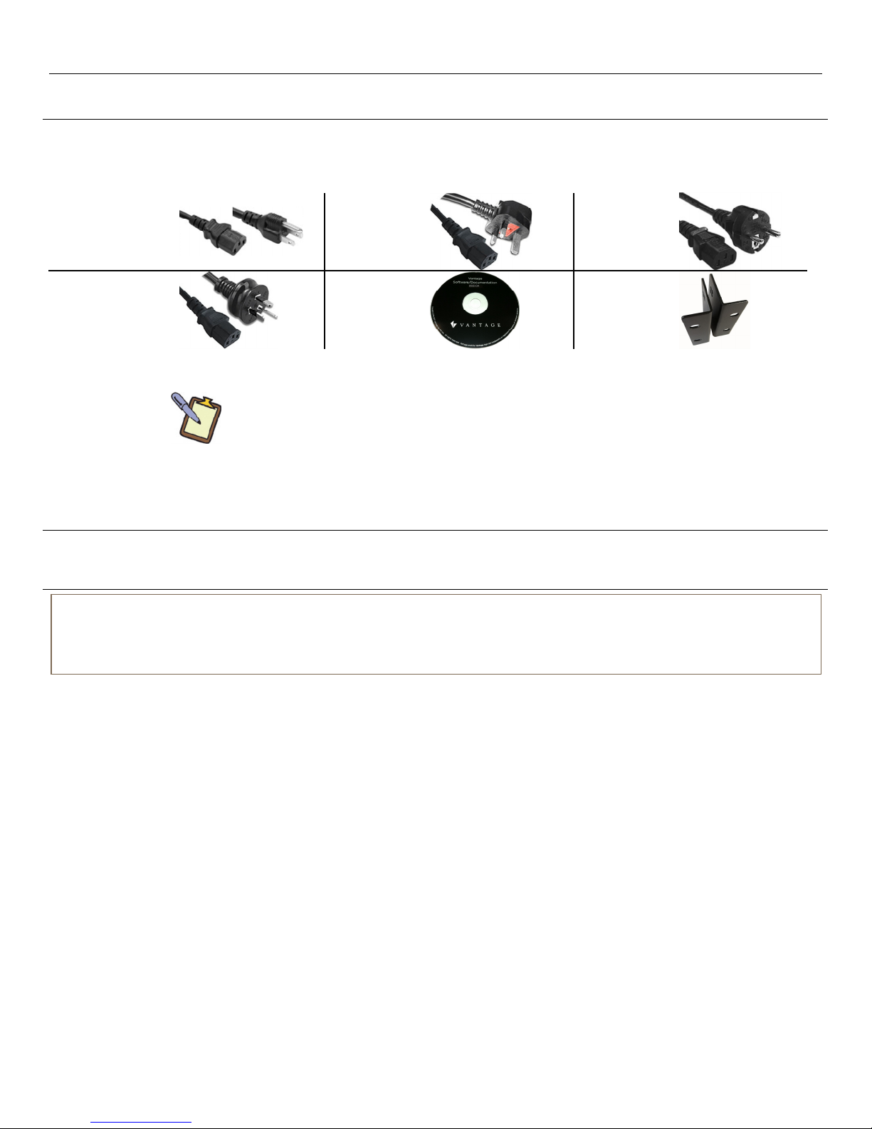
Use speaker wire pins for wire larger than 14AWG.
SECTION 1 – Quick Install Overview
Congratulations on purchasing Vantage's 850D-DA, Digital
Distributed Audio Amplifier. Please read this manual
thoroughly before making connections and plugging in the
unit. Follow the instructions in this manual to obtain optimum
performance and enjoyment from the new Vantage, 850D-DA
amplifier. Please retain this manual for future reference.
Unpacking / Setup
Check for damage:
oImmediately upon receiving the new 850D-DA Digital
Distributed Audio Amplifier, inspect the carton for
evidence of mishandling during shipment.*Then
carefully unpack the unit and inspect for damage.
Please save the shipping carton and all inner packing
materials in the event that the 850D-DA needs to be
shipped for service or moved to a new location.
*IMPORTANT: If the 850D-DA digital amplifier has been
damaged during shipping, please contact a
Vantage supplier immediately.
Read this entire Instruction Manual.
Verify that all accessories have been included, see, Preface
and Safety Instructions / Supplied Accessories.
Connect sources 1-8 using RCA Coax Digital Audio and/or
analog stereo. Connect sources 9-12 using Optical Digital or
RCA Coax Digital Audio. RCA Coax Digital connections are
RCA type SPDIF (S/PDIF-Sony/Phillips Digital Interface, aka
SPDIF) See SECTION 4 – Rear Panel Guide and SECTION 5 –
Installation Example.
NOTE: Sources 1-8 can accept two physical connections from
the same source when the source has both analog and digital
outputs. Depending on the media being played, the signal may
be encoded or un-encoded. The 850D-DA will automatically
select the correct source. If the signal sent is Encoded Digital
Audio, the amplifier automatically uses analog. If the signal is
un-Encoded the amplifier automatically uses the digital source.
Connect zones 1 – 6 to speakers via high quality speaker
audio cables (e.g., 16awg stereo audio cable or better).
oUse recommended wire size for distributed stereo
systems (use table above).
oWhen possible, keep LEFT and RIGHT speaker runs, in
that zone, the same length.
oAvoid crimping speaker wire (sharp 90bends should be
avoided)
oGenerally, in-wall speaker wire should be CL2R or CL3R
rated speaker wire. Check with local authorities for
distributed speaker wire rating requirements.
oSpeaker wire should be properly distanced from RFI
and/or EMI interference (e.g., keep at least 12" (305mm)
away from parallel high voltage house wiring).
In rare cases, if RFI and/or EMI interference is
unavoidable, the use of shielded speaker cable wire
may help, test first.
oDo not connect dual-coil speakers with shared left and
right channels for common. Speaker connections can
not be combined. In other words, the common/ground
speaker terminals from right channel and left channel
can not be paralleled/combined. In this amplifier,
speaker ground outputs are not common.
oZone 7 and Zone 8 are line-level outputs. Use high
quality shielded cable made for line level runs. Line level
wire run lengths are not published and must be tested
for noise and suitability. Vantage also recommends
using Stereo Audio Baluns for long, line-level runs.
Connect unit to the local network via the Ethernet port.
Connect Power cord to unit and then plug into an AC outlet
to apply power.
Connect / Configure unit to the InFusion System;
oVantage Controller using Ethernet;
Do not attempt to assign an IP address. A DHCP
address is assigned by the router or the 850D-DA
obtains an “AutoConf” IP address in a reserved range
the InFusion Controller can see.
Type the 850D-DA’s serial number in the Object
Editor inside of Design Center. The 850D-DA will
come on line when the InFusion controller is
programmed, or
Program the system and then click on Configure
Stations in Design Center. With the 850D-DA
highlighted in Design Center press the configuration
button which shows up on the touchscreen of the
amplifier or, press the Config. button on the back of
the 850D-DA (see page 5).
Special Notes For Setup
When replacing an 850D-DA amplifier in an existing
installation or adding as a new unit to an existing
installation, confirm that all firmware is the same on all
850D-DA, Digital Distributed Audio Amplifiers.
oFirmware is updated through Design Center software.
Use firmware that has been suggested for the version of
Design Center used on the current project.*To
determine which firmware is loaded, go to SECTION 7 –
Front Panel LCD Touchscreen Guide / Systems Settings
Page / Device Information Page. If updates are needed
or wanted, check the Vantage Dealer website for the
latest release of Design Center.
*NOTE: All firmware files, in each release of Design Center,
are the recommended versions at the time of
release. Some newer or older versions of firmware,
Driver Tools, Vantage InFusion Media etc. may or
may not be fully compatible. Vantage recommends
keeping all firmware versions as current as possible
and at the same time, use the firmware versions
recommended for the specific release of Design
Center used on each project. Please check the
Vantage Dealer Website for firmware updates,
http://dealer.vantagecontrols.com. Contact a
Vantage dealer for additional questions on
compatible firmware versions.
Each 850D-DA ships with 8 zones, 12 sources and 1
MediaPlayer (streaming network / NAS) source already
setup by default. When the 850D-DA is configured,
programmed and on line with the InFusion System, Design
Center automatically addresses the audio zones 1 through 8,
whether a single or multiple units configuration is used.
oWhen adding multiple 850D-DA units in Design Center,
the zone names are identical for each additional unit
added (i.e., Zone 1, Zone 2, Zone3, etc. is assigned for
each 850D-DA added). From Design Center, rename
the new zones, to help identify them properly when
programming. Design Center is able to differentiate
each zone due to unique VID numbers and parent ID,
but unique names will make selecting the correct zone
more intuitive to the programmer and client.
The 850D-DA has an onboard digital MediaPlayer source for
streaming local NAS (Network Attached Storage) music on
the local network via its Ethernet connection.

SECTION 2 – Features 850D-DA
850D-DA Digital Distributed Audio Amplifier
Installation Manual 41316 / 1308134-A © 2011 Page 2
SECTION 2 - Features
Multi-Zone, Multi-Source, Switching
The 850D-DA amplifier has six separate amplifiers and two
separate preamplifiers, providing 8 zones of independent yet
integrated control.
There are 12, buffered, input/output sources plus one
streaming source comprised of the following.
Sources 1 - 8 are either Analog Stereo (RCA), or Coax
(SPDIF) Digital Audio, or both.1
Sources 9 - 12 are either Coax (SPDIF) or Optical Digital
Audio.
Two contact inputs for door bells, etc., may be
programmed to internal decoded streams (virtual inputs)
by setting up page 1 and/or page 2 parameters. Up to four
door bell sound files may stored and each file may be up
to 480 KB in standard WAV format.
1NOTE: Sources 1-8 can accept two physical connections from
the same source when the source has both analog and digital
outputs. Depending on the media being played, the signal may
be encoded or un-encoded. The 850D-DA will automatically
select the correct source. If the signal sent is Encoded Digital
Audio, the amplifier automatically uses analog. If the signal is
un-Encoded the amplifier automatically uses the digital source.
Onboard MediaPlayer Digital Streaming Source
Vantage’s 850D-DA has an onboard digital media source, via
the local Ethernet connection, adding the ability to stream
most network based audio files. Please note, the onboard
MediaPlayer supports audio files with 1 or 2 channels and a
sample rate of ≤48kHz.
On Source Unit 1, the MediaPlayer Source has the ability to be
linked and buffering through multiple 850D-DA units playing,
synchronized, across each unit’s zones assigned to source 12.
Please see Section 6 and Section 8 for additional detail.
TIPS:
The MediaPlayer (streaming network) source via the
Ethernet connection is a streamed source comprised of
sound files which are not compressed or changed in
quality by streaming over the local network.
This source uses a network storage device or similar
connected music source to play media files, AKA, NAS
storage devices.
Supported File Types: Ogg Vorbis, MP3, MP1/MP2, MPEG4,
HE-AAC v2, WAV and FLAC.
oThe onboard MediaPlayer supports audio files with 1
or 2 channels and a sample rate of ≤48kHz.
Organize music files on the NAS device into folders. When
organizing the songs for each folder of music on the NAS
drive, think of each folder as a Playlist or Genres. This will
allow a better interface, allowing the user to select a UNC
knowing what music/type will be streamed. See Section 7 |
MediaPlayer Page for UNC setup.
Streaming supports Previous, Next, Pause, Stop, and Play.
If Stop is selected instead of Pause, the next time Play is
pressed the playing list starts over.
Preamp Zones and Amplified Zones
Each output zone supports, independent bass, treble,
loudness, balance, volume, maximum volume, and mute
control. Each output has a delay feature; range is from 0ms to
315ms. These settings are accessed through Design Center
programming or through the front panel program. The
maximum volume setting is useful for protecting connected
speakers. It may be applied to both amplifier and preamplifier
outputs.
Amplifier Power, Protection, and Clipping Indicators
Each zone supports 50Watts per channel at 8 ohms and is
capable of being driven into 6 or 4 ohm loads. The amplifiers
are protected against short-term output shorts. The front panel
zone indicators will momentarily turn red when the zone
amplifiers are over-driven into clipping. The amplifiers have
programmed algorithms that prevent hard clipping when the
zone amplifiers are over driven.
Thermal Control: Power Inputs and Zone Outputs
This unit has built-in thermal protection for low voltage, high
voltage, and two progressive levels for zone outputs.
Description of zone output protection levels:
LEVEL 1 - The amplifier volume is reduced 20dB.
LEVEL 2 - All internal amplifiers are shutdown until the
temperature reduces below the first level.
Care should be taken to ensure adequate ventilation - see
"Important safety instructions" at the beginning of this
Instruction Manual.
Ethernet Bus, USB, and IR Control
The 850D-DA amplifier may be controlled and monitored from
InFusion Design Center, touchscreens, mobile interfaces, the
unit’s front panel touchscreen, and the USB*on rear panel. IR
control is also possible but does not provide system status
feedback.
* The USB connection is for diagnostic purposes
and is not used with a Vantage InFusion System.
In multi amplifier installations - where the amplifiers are
interconnected via SPDIF - each of the 850D-DA amplifiers
require a connection to the local network in the stack of
amplifiers.
In standalone installations, an 850D-DA amplifier may receive
IR directly from the receiver on the front panel of any amplifier
and pass the information to other 850D-DA units in a stack if
the units are connected via the expansion bus. There are zone
specific IR commands and also a set of global IR commands.
Zone Specific
IR Commands:
ON, OFF, Standby (toggling),
Mute, Amp Volume Up, Amp Volume Down,
Pre Volume Up, Pre Volume Down,
Source Selects
Global IR
Commands:
PRESET 1 – PRESET 6,
Alarm Enable, Alarm OFF, & 5 minute Sleep
Real Time Clock Applications
Using the InFusion Controller’s internal real time clock or
astronomical clock, the amplifier may be setup to function as
an alarm clock. Alarm clock programming possibilities are
potentially limitless in Design Center software. The InFusion
System clock continues to operate up to 2.5 years un-powered
(dependent on the InFusion Controller battery’s condition).
The 850D-DA amplifier is also equipped with a real time clock.
The InFusion controller periodically sends time information to
the amplifier keeping the amplifier’s time synchronized with
the InFusion System. The amplifier may be set up to function
as an alarm clock via the front panel and from Design Center.
For example, at 6:30am in the morning, five days a week, the
master bedroom zone could be made to turn on using
programmed parameters (e.g., select tuner, specific volume
level, etc.). Multiple Alarms are feasible (max. of 14). The Clock
can be set to automatically compensate for daylight saving.
The clock continues to operate, typically > 48 hours, without
power - more than enough to keep the time current during
extended power outages.

SECTION 2 – Features 850D-DA
850D-DA Digital Distributed Audio Amplifier
Installation Manual 41316 / 1308134-A © 2011 Page 3
Presets and Paging
There are fourteen amplifier presets and two Page presets..
NOTE: To properly setup Presets from Design Center, the
amplifier must be connected and configured to the system.
1. 14 Program Presets.
a) Page 1 and 2 use 1 of 4 uploaded sound files, however
Page 2 must be assigned to one of the other 14
Presets.
i. Page 1: Select 1 of 4 sound files to automatically
play when triggered by a contact, typically a Door
Bell or from a programmed task, time control, etc.
ii. Page 2: Select 1 of 4 sound files to automatically
play when triggered by a contact and must be
assigned to one of the 14 Presets. Page 2 may also
be triggered from a programmed task, time control,
etc.
b) All Presets may be tied to internal programmed alarms
or InFusion programmed alarms for specific time of
day execution.
i. Please note that output zones have a Do Not
Disturb feature that may be toggled, allowing or
preventing a programmed alarm in that zone.
ii. Alarms support Time (including daylight savings)
and individual Day of Week setup.
c) Presets can be named through Design Center software
2. Preset Feedback reports to the InFusion Controller
through the Ethernet Bus
Zone Linking
Zone linking is part of the Zone Settings menus and ties all
selected zones together. A zone may be setup to link with any
combination of zones or all zones. The zone that is being
actively edited determines the source of the other linked
zones. Linked zones can also link volume and/or standby,
however the volume and standby may be left independent of
the zone link. This is useful for closely coupled audio areas
where it is advantageous to have different volume control but
the same source, or the same volume with separate standby
control, and etc. Zone linking from Design Center’s Procedure
Wizard (tasks) allows source, selected zones, volume and
standby in any combination. Zone linking is not possible from
Design Center’s Live Source Control; see Section 8 for
information about Live Source Control.
72 Maximum Number of Zones
The system may be expanded up to 72 zones (nine units) of
possible control. Through Design Center and the InFusion
system each zone on the 850D-DA amplifier, is different or
independent, even when they have the same name. However,
in a standalone installation, multiple amplifiers connected via
the expansion bus, share the same zone names causing the
zones to mimic each other and act as a single zone unless
renamed through the front panel user interface. To reiterate,
when using an Infusion Controller, the zones may have the
same name, but the zone’s address is assigned by the Infusion
Controller and duplicate zone IDs are not allowed.
Expansion Bus
On the InFusion System, multiple 850D-DA amplifiers may be
linked or distributed throughout the project as separate,
independent, units. In a linked configuration, the source
equipment’s audio outputs must be plugged into the first
amplifier where they are buffered and sent to the next
amplifier. The maximum number of linked units is nine. When
linked, each unit is connected to the next using a standard
Ethernet patch cable to and from the Expansion Bus ports to
enable communication among multiple amplifiers. Linked or
separate, Vantage requires that each unit be connected to
the local network via a standard Ethernet connection.
Conversely, the Expansion Bus is not used on the 850D-DA if
the units are independent and each unit must have its own
audio source equipment.
Zone ON Outputs - “Amp-On”
Each zone has connections for AMP-ON status: 12VDC OUT on
the rear panel connector: (1, 2, 3, 4, 5, 6, 7, 8). These outputs
activate a secondary AMP (e.g., the Vantage 7+7 Watt
Amplifier Series, part number AX-07S). The OV terminal is the
common (shared) terminal for the 8 AMP-ON terminals. Please
note that the AMP ON outputs are protected against shorts.
Power Failure Restoration
After an AC power outage the 850D-DA amplifier restores its
settings to the pre-interrupted state. All internal settings are
stored in non-volatile memory, except the clock that runs for
at least 48 hours on stored power. When power is restored the
unit will always reset its internal clock to the InFusion
Controller’s time.
Restore Defaults
The 850D-DA amplifier may be readily set to the default
settings. Factory defaults resets the zone allocations back to
1 - 8, clears all zone and source names, presets, zone links,
maximum volume limits, bass, treble and loudness settings. See
SECTION 7, Front Panel LCD Touchscreen Guide.
Setup Lockout
Locks access to the System Setup menus where critical
installation adjustments can be made. A press and hold for
about 5 seconds on the Lock icon will unlock the setup.
Firmware Upgradable
The 850D-DA’s firmware may be updated via Design Center
over the Ethernet Bus connection. Please check the Vantage
Dealer site for firmware updates. Typically the latest release of
Design Center will have the latest 850D-DA firmware. See
SECTION 1 / Special Notes For Setup.

SECTION 2 – Features 850D-DA
850D-DA Digital Distributed Audio Amplifier
Installation Manual 41316 / 1308134-A © 2011 Page 4
30
Ω
, 5W
Door Bell
Button
RESISTOR 12VDC, 600mA
Power Supply
Door Bell
Up to four door bell sound files may be stored directly on the
850D-DA. Each sound file may be up to 480 KB in standard
WAV format. Upload door bell sound files to the 850D-DA via
Design Center software. The sound files may be played back
by Page 1 or Page 2 programming.
It is also possible, through Design Center programming, to play
any source file through any of the 850D-DA amplifier zones as
a result of either page 1 or page 2 contact closure triggers. Use
this method for door bell sounds as an alternative to copying
the page sound files directly to the 850D-DA’s own page file as
the source (e.g., play a sound file from Vantage’s DMM).
Page 1 and 2 require an outside 12-24V AC/DC power supply.
The contact closure must have an external power source, (i.e. a
12 – 24V AC/DC powered door bell). When the Page Call is
released the amplifier zones return to their previous states.
PG1 is always assigned to the Page 1 Preset.
PG2 may be assigned to any one of the 15 available Presets.
For page 1 and 2 contact wiring, see Doorbell Wiring Example
below using a 12VDC, 600mA power supply with a 30Ω,
5Watt Resistor.
Doorbell Wiring Example*
The contacts, Page 1 and Page 2, require a 12VDC power
supply. The example below illustrates, in a very simplistic way,
how Page 1 could be wired to a lighted doorbell to enable
auto-paging. This example bypasses the doorbell’s built-in
chimes. The P1 screw terminal connects to the 12VDC power
supply and the doorbell button. The Cscrew terminal connects
to the doorbell button and the 30Ω, 5Watt Resistor. The
other end of the resistor connects to the negative or common
side of the 12VDC power supply, as illustrated.
* NOTE: This example assumes new construction and requires
the door bell button, but does not require the traditional
doorbell chime and AC power supply. If an existing door bell
system is in place, the electromagnetic relay of the chime
replaces the 30Ωresistor and the AC transformer replaces the
12VDC, 600mA power supply.
Page 1 Wiring Example
A second doorbell can be attached to P2 following the same
procedure.

SECTION 3 – Front Panel Guide 850D-DA
850D-DA Digital Distributed Audio Amplifier
Installation Manual 41316 / 1308134-A © 2011 Page 5
SECTION 3 – Front Panel Guide
Descriptions
1. Front Panel
Solid aluminum front panel using Vantage’s custom design.
This design is used in the Vantage 1080HD video switcher,
DMM-4S multi-zone audio distributor and the IRX II units
making it a perfect match in a rack or stack system.
2. Infra-Red Receiver
Receiver for front panel IR control - Used only for amplifier
control, not IR pass through.
3. Power Indicator
The power indicator glows blue whenever AC power is
applied.
4. Color TFT LCD & Resistive Touch Panel
LCD Touch Panel display for menu guided control and
programming. The display is dimmed to "Off" after 15
minutes of inactivity.
5. Chassis Feet
High*enough to provide unrestricted airflow through the
chassis for convection cooling when placed on an unheated,
solid surface. The 850D-DA amplifier fits in a standard 19
rack 2U space. See Important Safety Instructions for proper
ventilation at the beginning of this document.
*NOTE: Do not place amplifiers on top of each other in linked
configurations, unless 1U of space is provided between each
850D-DA amplifier. Do not place the 850D-DA amplifier on top of
another, third-party amplifier.

SECTION 4 – Rear Panel Guide 850D-DA
850D-DA Digital Distributed Audio Amplifier
Installation Manual 41316 / 1308134-A © 2011 Page 6
SECTION 4 – Rear Panel Guide
Rear Panel Guide
Rear Panel Guide Details
1. AC Inlet
IEC socket.
2. Speaker Terminals
Plug in terminal clamp connectors accept up to 2.5mm2
/ 14awg speaker wires. For larger wire use speaker wire
pins. See SECTION 1 - Quick Install Overview, speaker
connections.
3. Expansion Bus
Used when linking multiple amplifiers requiring
communicate with each other and sharing audio
sources.
Not used if multiple amplifiers are to remain
independent.
4. Coax, Optical, and Analog Source Terminals
Coax digital (SPDIF) outputs for sources 1 through 12
are for expansion to further amplifier zones in a stack.
All SPDIF coax channels are buffered to keep additional
zones synchronized. Always connect the coax SPDIF
Output to the coax (SPDIF) Input in a stack. Follow this
rule even if sources are connected via the analog or
optical inputs. The 850D-DA converts all connected
audio to digital format for additional units.
Coax digital (SPDIF) inputs for sources 1 through 12.1
1NOTE: Sources 1-8 can accept two physical connections from
the same source when the source has both analog and
SPDIF outputs as in many Blu-ray players. Depending on
the media being played, the signal may be analog or
digital. The 850D-DA will automatically use SPDIF
instead of analog when the audio signal is digital.
5. USB For Programming
USB mini B socket for standalone programming,
firmware updates, and trouble-shooting. No end user
applications supported.
6. Ethernet Bus Port
Allows communication between the 850D-DA and the
InFusion Controller via the Vantage Ethernet Bus.
Connect to a standard network switch or router. All IP
settings are managed and auto detected by the
InFusion system and usually does not need to be
modified. Do not attempt to assign an IP address.
7. Line-Level / Preamplifier Zones Out
Pre-amp / line level, L&R analog audio outputs for Zone
7 and Zone 8. Use high quality shielded cable for line
level runs.
8. Config Button
Used to configure the 850D-DA amplifier, when using
the configure stations button in Design Center.
9. Status LED Indicator
This red LED has various flash/pause intervals indicating
configuration and connection status. The serial number
of the 850D-DA may also be typed directly into Design
Center and when the system is programmed the 850D-
DA should be on line within ten minutes.
Blink patterns:
Steady blink = Configured.
Triple Blink = Connected to network but not
configured in Design Center.
Five Blink = Configuration Mode, press the Vantage
configure button to configure. The
850D-DA must be selected in Design
Center before pressing the configure
10. “AMP ON” and “PAGE” Control
AMP-ON 1 - 8 terminals, output 12VDC when the zone is
ON. This may be used to trigger secondary amplifiers
not controlled by the InFusion System. Note, that OV is
the shared common for AMP-ON 1 - 8 terminals.
Page 1 and 2 from a 12 - 24V AC/DC powered doorbell.
Connect the doorbells 12-24V AC/DC to the P1 or P2
terminal and the doorbells common to the Cterminal.
Continue the P1 or P2 and C wires to the doorbell.
Button. Closure between P1 or P2 and C invokes a
preset enabling paging or doorbell function. See Door
Bell example on page 4 for additional information.

SECTION 5 – Installation Example 850D-DA
850D-DA Digital Distributed Audio Amplifier
Installation Manual 41316 / 1308134-A © 2011 Page 7
Kitchen
DMM
BLU-RAY
TUNER
ZONE 8
1080HD
Amplifier
Wiring Key
Source I
N
Z
one OU
T
Line OU
T
Page
Networ
k
SOURCE
ZONE
LINE
DOOR
CONTACT
ETHERNET
ZONE 4 ZONE 5 ZONE 6 ZONE 7
ZONE 1 ZONE 2 ZONE 3
Exercise RoomGuest BedroomMaster Bedroom
Living Room Office Rec. Room
ETHERNET
PAGE 2
PAGE 1
Amplifier
LINE 8
LINE 7
SECTION 5 – Installation Example
Sources, distribution, and other connections:
Typical Installation Example
The figure above depicts a typical installation configuration where the 850D-DA audio amplifier provides independent audio source1
selections to eight remote locations/devices. Notice: Zone 7 is a line level, analog, right / left audio out to a remote amplifier and Zone
8 is also a line level, analog, right / left audio out to another amplifier. Use high quality shielded cable for line level runs.
1NOTE: Sources 1-8 can accept two physical connections from the same source when the source has both analog and SPDIF outputs
as in many Blu-ray players. Depending on the media being played, the signal may be analog or digital. The 850D-DA will automatically
use SPDIF instead of analog when the audio signal is digital.

SECTION 5 – Installation Example 850D-DA
850D-DA Digital Distributed Audio Amplifier
Installation Manual 41316 / 1308134-A © 2011 Page 8
CD PLAYER
Wiring Key
Source IN
Z
one OUT
Line OUT
SOURCE
ZONE
LINE
ZONE 4 ZONE 7
Music Room
Main Speakers
Sub-
woofer
Subwoofer Installation Example:
Subwoofer Installation Example
The figure above depicts an installation configuration using the 850D-DA audio amplifier to power main speakers and a self-powered
subwoofer. The preamplifier zone, Zone 7 in this example, can be used to provide line level output for a powered subwoofer. The above
example links the preamplifier zone 7 to the digital amplifier zone 4 through the Link Zone command. Now the two zones will share the
same sources and volume.
CAUTION: See cautionary information (next page) concerning Linking Preamplified Z7 or Z8 With Amplified Zones Z1 – Z6

SECTION 5 – Installation Example 850D-DA
850D-DA Digital Distributed Audio Amplifier
Installation Manual 41316 / 1308134-A © 2011 Page 9
Control
The 850D-DA is controlled using the Vantage InFusion
controller over the Ethernet Bus. Connect the 850D-DA to the
local area network using a standard Ethernet patch cable.
Control from InFusion includes TPT touchscreens, portable
mobile devices connected to the local network, and other
wired devices on the InFusion System. NOTE: USB, RS232 and
IR control means are also available for third-party control or
testing.
Source Equipment
Sources 1 – 8: The 850D-DA amplifier has eight stereo RCA
audio inputs for connecting to source
equipment. These eight channels also feature
coax digital (SPDIF) inputs. Vantage
recommends using the digital inputs
whenever possible.1
1
NOTE: Sources 1-8 can accept two physical
connections from the same source when the
source has both analog and SPDIF outputs
as in many Blu-ray players. Depending on
the media being played, the signal may be
analog or digital. The 850D-DA will
automatically use SPDIF instead of analog
when the audio signal is digital.
Sources 9 – 12: There are four additional Digital only input
channels featuring coax (SPDIF) or Optical
connections.
Any output zone may select any of the connected sources. For
example, classical music may be playing in the lounge, while
nature sounds are playing in the Study.
All eight zones or stacked zones may be assigned to the same
source, or any combination of zones may be assigned to the
same source. Only one source may be connected to one
source input.
Source Onboard MediaPlayer:
Vantage’s 850D-DA has an onboard digital media source, via
the local Ethernet connection, adding the ability to stream
most, 1 or 2 channel files at ≤48kHz, network based audio
through the 850D-DA’s stereo, multi-zone system.
On Source Unit 1, the MediaPlayer Source has the ability to be
linked and buffering through multiple 850D-DA units playing,
synchronized, across each unit’s zones assigned to source 12.
Please see Section 6 and Section 8 for additional detail.
The onboard MediaPlayer (streaming network) source via
the Ethernet connection is a streamed source comprised of
sound files which are not compressed or changed in
quality by streaming over the local network.
oThis source uses a network storage device or similar
connected music source to play media files from
storage devices like the Vantage DMM or a NAS drive,
etc.
oSupported File Types: Ogg Vorbis, MP3, MP1/MP2,
MPEG4, HE-AAC v2, WAV and FLAC.
NOTE: The onboard MediaPlayer supports audio files with 1
or 2 channels and a sample rate of ≤48kHz.
Speakers
Speakers in each zone are connected to the amplifier by
"Home Run" speaker cables. Please see SECTION 1 - Quick
Install Overview, for recommended speaker wire.
Preamplifier Zone Outputs
Output zones 7 and 8 are line-level outputs. These preamplifier
output zones are completely independent of the digital
amplifier zones and of each other. These may be used for
locations where a higher or lower power amplifier / speaker
would be required. A third party power amplifier is required to
power these zones to speakers. See cautionary information
below.
Linking Preamplified Z7 or Z8 With Amplified Zones Z1 – Z6
Over amplification may damage third party
equipment. Employ caution using line-level outputs
to third party amplified equipment. Test equipment
connected to either zone 7 or zone 8 line-level
outputs to prevent over amplification. Due to varying gains of
third party amplifiers attached to Z7 or Z8, it is recommended
that the attached equipment have independent
attenuation/volume control. This can help the installer set a
trimmed level so the third party equipment is able to handle
either line-level Zones 7 or 8 when set to their maximum
output.
It is also possible to set the Max Volume level of zone 7 or
zone 8; this also helps prevent over amplification of the
attached equipment. Please note when linking volume, the Max
Volume level of each zone in the link is still enforced. For
example if zone 4 and zone 7 are linked including volume, and
the Max Volume of zone 4 is set to 100% and the Max Volume
of zone 7 is set to 50%, raising the linked volume control to full
on will result in zone 4 being at level 100% and zone 7 being at
level 50%. This is another way to help minimize potential
damage if the attached equipment cannot handle the line
level’s maximum output.
Summary
A preamplifier zone may be linked to one of the digital
amplifier zones or have an independent connection to a third-
party amplifier. This provides a line level output to another
speaker source, such as a subwoofer, as in the example on
page 7. The preamplifier zone and the amplified zone are
linked through the Link Zone command, allowing the two
zones to share the same source, and have a single volume
control or separate volume controls, etc.

SECTION 6 – Multiple Amplifiers Linked 850D-DA
850D-DA Digital Distributed Audio Amplifier
Installation Manual 41316 / 1308134-A © 2011 Page 10
Receiver
EXPANSION – UNIT 2
SOURCE – UNIT 1
Use Ethernet patch cables
for linked configurations
SPDIF OUT
TO
SPDIF IN
ETHERNET
ETHERNET
Satellite
CD
Player
Tuner
DMM
Buffered digital (SPDIF) out to next
850D-DA Digital Distributed Audio Amplifier
SECTION 6 – Multiple Amplifiers Linked
Linked Example:
Linking Multiple 850D-DA Amplifiers
Link multiple 850D-DA units to add additional audio zones within a project. When linking the 850D-DA, connect each unit via the
expansion bus using standard Ethernet patch cables. Each 850D-DA must have its own dedicated Ethernet Bus connection to the
local network as illustrated. The source equipment’s audio outputs are connected to the first 850D-DA unit in the stack. This is known
as the source unit. Audio signals are buffered and sent to the next amplifier in the stack via the SPDIF out to the SPDIF in using RCA
type connectors. The maximum number of 850D-DA amplifiers in a multiple unit configuration is nine (9). This allows 72 zones of
stereo audio.

SECTION 6 – Multiple Amplifiers Linked 850D-DA
850D-DA Digital Distributed Audio Amplifier
Installation Manual 41316 / 1308134-A © 2011 Page 11
EXPANSION – UNIT 2
SOURCE – UNIT 1
Use Ethernet patch cables
for linked configurations
SPDIF OUT
TO
SPDIF IN
ETHERNET
ETHERNET
Satellite
CD
Player
Tuner
DMM
Buffered digital (SPDIF) out to next
850D-DA Digital Distributed Audio Amplifier
MediaPlayer
Streamed Source is
routed to S12 out
and sent to next
850D-DA
Receiver
Linked MediaPlayer Example:
Media Player Linking Multiple 850D-DA Amplifiers
On Source Unit 1, MediaPlayer Source has the ability to be linked through multiple 850D-DA units thus buffering the source to play
synchronized across each unit’s zones assigned to source 12. In Design Center from the source unit 1, place a check in the Output on
S12 OUT checkbox. By checking this box, the media player source selected on unit 1 is routed internally to the source 12 SPDIF output.
In a linked configuration, additional units, set to source 12 will automatically play the MediaPlayer source from the main 850D-DA
amplifier in unison. Design Center will also automatically set a zone’s source to 12 if the zone is set to the media player source and this
checkbox is checked.

SECTION 7 – Front Panel LCD Touchscreen Guide 850D-DA
850D-DA Digital Distributed Audio Amplifier
Installation Manual 41316 / 1308134-A © 2011 Page 12
SECTION 7 – Front Panel LCD Touchscreen Guide
Front Panel Touchscreen Guide
The Vantage 850D-DA amplifier has a 2.4” LCD touch panel color display used for initial zone settings, system settings, trouble
shooting, and local control of the unit. The screens are intuitive and can be learned fairly quickly. Use the front screen interface for
stand-alone systems only; use Design Center for all setup and programming, with the exception of Lock-out mode. The touchscreen is
simply a tool*for local control, information, etc., of the 850D-DA amplifier.
*Please Note: Anything that can be managed from the front panel touchscreen should be managed
from Design Center software and the InFusion system via programmed tasks.
After 2 minutes of inactivity the LCD dims to 50% brightness, after a further 15 minutes it turns off. If the screen is off, the first touch
will restore the LCD to full brightness, enabling touch control.
Zone Settings Path
Home Page
Select Zone Settings on the
Home page.
Zones Page
On the zones page, it is possible
to:
Toggle zone power
Adjust or mute the volume
Change the source
Scroll through Zones by
threes using up and down
arrows
Return to Home
Press and hold any zone for
1 second to move to the selected zone’s individual setup.
Selected Zone Setup Page
On the Zone Edit page, it is
possible to:
Edit the zone name
Edit zone number
oUse when multiple 850D-
DA units are connected –
72 zones maximum (0-
71)
Edit linked zones
Navigate to Equalizer,
Delay, and Levels pages
Navigate to previous or next zone page
Zone Equalizer Page
On the Zone Equalizer page it is
possible to:
Edit the bass level
Edit the treble level
Toggle the zone Loudess
button
Navigate back to the Zone
Setup page
Zone Delay Page
On the Zone Delay page it is
possible to:
Edit the Delay time interval
(i.e., lip-sync a video)
Range may be set from 0ms
to 315ms
Navigate back to the Zone
Setup page
Default all set to 0ms
Zone Levels Page
On the Zone Levels page it is
possible to:
Edit maximum volume level
Range may be set from 20
to 100 percent of volume
range (minimum volume
level is 20)
Adjust the left and right
balance
Navigate back to the Zone
Setup page
Edit Zone Name Page
On the Edit Zone Name page it
is possible to:
Edit the zone name via a
soft keyboard
Press and hold buttons for
different amounts of time to
change selected button’s
character / case
Save or Cancel changes
Save and Cancel Navigates
back to the Zone Setup page
Table of contents
Other Vantage Hearth Amplifier manuals
Popular Amplifier manuals by other brands

Behringer
Behringer Ultrabass BX600 Technical specifications

THORLABS
THORLABS LIA100 Operation manual

Rockford Fosgate
Rockford Fosgate Power 360 installation manual

Audio Note
Audio Note PALADIN Owner's Information

JL Audio
JL Audio NexD2 MV1000/1 Connection guide

System Fidelity
System Fidelity SA-D30 manual