Varec 4120 User manual

Varec, Inc.
5834 Peachtree Corners East, Norcross (Atlanta), GA 30092 USA
Tel: +1 (770) 447-9202 Fax: +1 (770) 662-8939
www.varec.com
4120 IOM006GVAE1103
Multi-Element Temperature Transmitter
Highly accurate and effective transmission of temperature data
Installation and
Operations Manual

Multi-Element Temperature Transmitter
1 Installation and Operations Manual

IOM006GVAE1103 2
4120
Copyright
All rights reserved. Printed in the United States of America.
Except as permitted under the United States Copyright Act of 1976, no part of this
publication may be reproduced, stored in a retrieval system or transmitted in any form
or by any means- electronic, mechanical, photocopying, recording or otherwise-
without the prior written permission of the Publisher:
Varec, Inc.
5834 Peachtree Corners East
Norcross (Atlanta), Georgia 30092
Phone: (770) 447-9202
Fax: (770) 662-8939
Trademarks acknowledged
Trademarks of other products mentioned in this manual are held by the companies
producing them.
FuelsManager® is a registered trademark of
Varec, Inc.
Microsoft® is a registered trademark of Microsoft
Corporation.
Acrobat® is a registered trademark of Adobe Systems
Incorporated.
MODBUS® is a registered trademark of Modicon, Inc.
TIWAY® is a registered trademark of Texas Instruments
Corporation
Varec® is a registered trademark of Varec, Inc.
HART® interface is a registered trademark of HART
Communications Foundation
All other trademarks are acknowledged.
Revision Control Original Issued: August 1995

Multi-Element Temperature Transmitter
3 Installation and Operations Manual
Disclaimer of Warranties
The contract between the Seller and the Buyer states the entire obligation of the Seller.
The contents of this instruction manual shall not become part of or modify any prior or
existing agreement, commitment or relationship between the Seller and Buyer. There are
no express or implied warranties set out in this instruction manual. The only warranties
that apply are those in the existing contract between the Seller and Buyer.
Varec Model 4120 has not beentested by Varec under all
possibleoperational conditions, and Varec maynot have all the data relative
to your application. The information in this instruction manual is not all inclusive and
does not and cannot take into account all unique situations. Consequently, the user
should review this product literature in view of his/her application. If you have any
further questions, pleasecontact Varec for assistance.
Limitations of Seller's Liability
In the event that a court holds that this instruction manual created some new warranties,
Seller's liability shall be limited to repair or replacement under the standard warranty
clause. In no case shall the Seller's liability exceed that stated as Limitations of Remedy
in the contract between the Seller and Buyer.
Use of parts that are not manufacturedor suppliedby Varec voids any
Varec warranty and relieves Varec of any obligation to service the
product under warranty. Varec recommends the use of onlyVarec
manufactured or supplied parts.
Terms of Use
The information provided in this document is provided "as is" without warranty of any
kind. Varec, Inc. disclaimall warranties, either express
or implied, including the warranties of merchantability and fitness for a particular
purpose. In no event shall Varec, Inc. or its suppliers be
liable for any damages whatsoever including direct, indirect, incidental, consequential,
loss of business profits or specialdamages, evenif Varec,Inc
or its suppliers have been advised of the possibility of such damages.

IOM006GVAE1103 4
4120
Safety Precaution Definitions
The following typesof warnings havebeen catagorized by Varec for this
product. Read and understand this Manual before installing, operating or performing
maintenance on a Model 2500 Automatic Tank Gauge. Follow all precautions and
warnings noted herein when installing, operating or performing maintenance on this
equipment.
Safety Precautions
Note!
Follow these specific instructions to optimize the procedure or process
Caution!
Damage to equipment may result if this precaution is disregarded.
Warning!
Direct injury to personnel or damage to equipment which can cause injury to personnel may result if this precaution is not fol-
lowed.
Caution!
Read and understand static and lightning electrical protection and grounding described in API 2003. Make certain that the tank
installation, operation and maintenance conforms with the practice set forth therein.
Warning
Make certain that the tank is empty and not in service. Ensure that the tank has been leak and pressure tested as appropriate for
the liquid to be stored. Observe appropriate safety precautions in flammable or hazardous liquid storage areas. Do not enter a
tank that has contained hydrocarbons, vapors, or toxic materials, until a gas-free environment is certified. Carry breathing
equipment when entering a tank where oxygen may be displaced by carbon dioxide, nitrogen or other gases. Wear safety glasses
as appropriate. Use a hard hat.
Warning!
Read and understand this instruction manual before installing, operating or performing maintenance on the Varec Model 4120
Multi-Element Temperature Transmitter. Follow all precautions and warnings noted herein when installing, operating or perform-
ing maintenance on this equipment.

4120
IOM006GVAE1103 5
Table of Contents
Copyright . . . . . . . . . . . . . . . . . . . . . . . . . . . . . . . . . . . . . . . . . . . . . . . . . . . . . . . . . . . . . . . . . . . . . . . . . . . 2
Revision Control . . . . . . . . . . . . . . . . . . . . . . . . . . . . . . . . . . . . . . . . . . . . . . . . . . . . . . . . . . . . . . . . . . . . . 2
Acknowledgments . . . . . . . . . . . . . . . . . . . . . . . . . . . . . . . . . . . . . . . . . . . . . . . . . . . . . . . . . . . . . . . . . . . . 2
Disclaimer of Warranties . . . . . . . . . . . . . . . . . . . . . . . . . . . . . . . . . . . . . . . . . . . . . . . . . . . . . . . . . . . . . . . 3
Limitations of Seller's Liability . . . . . . . . . . . . . . . . . . . . . . . . . . . . . . . . . . . . . . . . . . . . . . . . . . . . . . . . . . . 3
Safety Precaution Definitions. . . . . . . . . . . . . . . . . . . . . . . . . . . . . . . . . . . . . . . . . . . . . . . . . . . . . . . . . . . . 4
Safety Precautions. . . . . . . . . . . . . . . . . . . . . . . . . . . . . . . . . . . . . . . . . . . . . . . . . . . . . . . . . . . . . . . . . . . . 4
Table of Contents . . . . . . . . . . . . . . . . . . . . . . . . . . . . . . . . . . . . . . . . . . . . . . . . . . . . . . . . . . . . . . . . . . . . . 5
List of Illustrations . . . . . . . . . . . . . . . . . . . . . . . . . . . . . . . . . . . . . . . . . . . . . . . . . . . . . . . . . . . . . . . . . . . . 5
Section 1 - Introduction and Installation . . . . . . . . . . . . . . . . . . . . . . . . . . . . . . . . . . . . . 7
Using This Manual . . . . . . . . . . . . . . . . . . . . . . . . . . . . . . . . . . . . . . . . . . . . . . . . . . . . . . . . . . . . . . . . . . . . 7
Getting Acquainted with the Multi-Element Temperature Transmitter (METT) . . . . . . . . . . . . . . . . . . . . . . 7
Installation . . . . . . . . . . . . . . . . . . . . . . . . . . . . . . . . . . . . . . . . . . . . . . . . . . . . . . . . . . . . . . . . . . . . . . . . . . 8
Section 2 - Operation . . . . . . . . . . . . . . . . . . . . . . . . . . . . . . . . . . . . . . . . . . . . . . . . . . . . 12
Temperature Configurations . . . . . . . . . . . . . . . . . . . . . . . . . . . . . . . . . . . . . . . . . . . . . . . . . . . . . . . . . . . 12
Temperature Averaging . . . . . . . . . . . . . . . . . . . . . . . . . . . . . . . . . . . . . . . . . . . . . . . . . . . . . . . . . . . . . . . 12
HART Communications Interface . . . . . . . . . . . . . . . . . . . . . . . . . . . . . . . . . . . . . . . . . . . . . . . . . . . . . . . 12
Varec Handheld Terminal Interface . . . . . . . . . . . . . . . . . . . . . . . . . . . . . . . . . . . . . . . . . . . . . . . . . . . . . . 13
Section 3 - Specifications and Reference Data . . . . . . . . . . . . . . . . . . . . . . . . . . . . . . . 17
Specifications and Physical . . . . . . . . . . . . . . . . . . . . . . . . . . . . . . . . . . . . . . . . . . . . . . . . . . . . . . . . . . . . 17
Functional . . . . . . . . . . . . . . . . . . . . . . . . . . . . . . . . . . . . . . . . . . . . . . . . . . . . . . . . . . . . . . . . . . . . . . . . . 17
Hazardous Location Approvals . . . . . . . . . . . . . . . . . . . . . . . . . . . . . . . . . . . . . . . . . . . . . . . . . . . . . . . . . 17
Environmental . . . . . . . . . . . . . . . . . . . . . . . . . . . . . . . . . . . . . . . . . . . . . . . . . . . . . . . . . . . . . . . . . . . . . . 17
Performance . . . . . . . . . . . . . . . . . . . . . . . . . . . . . . . . . . . . . . . . . . . . . . . . . . . . . . . . . . . . . . . . . . . . . . . 17
Physical . . . . . . . . . . . . . . . . . . . . . . . . . . . . . . . . . . . . . . . . . . . . . . . . . . . . . . . . . . . . . . . . . . . . . . . . . . . 17
Model Options . . . . . . . . . . . . . . . . . . . . . . . . . . . . . . . . . . . . . . . . . . . . . . . . . . . . . . . . . . . . . . . . . . . . . . 18
Section 4 - MFT/HIU and TankView Support for the METT . . . . . . . . . . . . . . . . . . . . . . 19
MFT/HIU Support. . . . . . . . . . . . . . . . . . . . . . . . . . . . . . . . . . . . . . . . . . . . . . . . . . . . . . . . . . . . . . . . . . . . 19
TankView Support . . . . . . . . . . . . . . . . . . . . . . . . . . . . . . . . . . . . . . . . . . . . . . . . . . . . . . . . . . . . . . . . . . . 19
Section 5 - HART Protocol Implementation . . . . . . . . . . . . . . . . . . . . . . . . . . . . . . . . . . 20
Transmitter Variables . . . . . . . . . . . . . . . . . . . . . . . . . . . . . . . . . . . . . . . . . . . . . . . . . . . . . . . . . . . . . . . . . 20
Standard HART Commands . . . . . . . . . . . . . . . . . . . . . . . . . . . . . . . . . . . . . . . . . . . . . . . . . . . . . . . . . . . 20
METT Device Specific HART Commands . . . . . . . . . . . . . . . . . . . . . . . . . . . . . . . . . . . . . . . . . . . . . . . . . 21
Command 130 - Write Level . . . . . . . . . . . . . . . . . . . . . . . . . . . . . . . . . . . . . . . . . . . . . . . . . . . . . . . . . . . 21
Command 131 - Read Temperature Configuration . . . . . . . . . . . . . . . . . . . . . . . . . . . . . . . . . . . . . . . . . .21
Command 132 - Write Temperature Configuration . . . . . . . . . . . . . . . . . . . . . . . . . . . . . . . . . . . . . . . . . .21
Command 133 - Read Temperature Element Height. . . . . . . . . . . . . . . . . . . . . . . . . . . . . . . . . . . . . . . . . 22
Command 134 - Write Temperature Element Height . . . . . . . . . . . . . . . . . . . . . . . . . . . . . . . . . . . . . . . . . 22
List of Illustrations
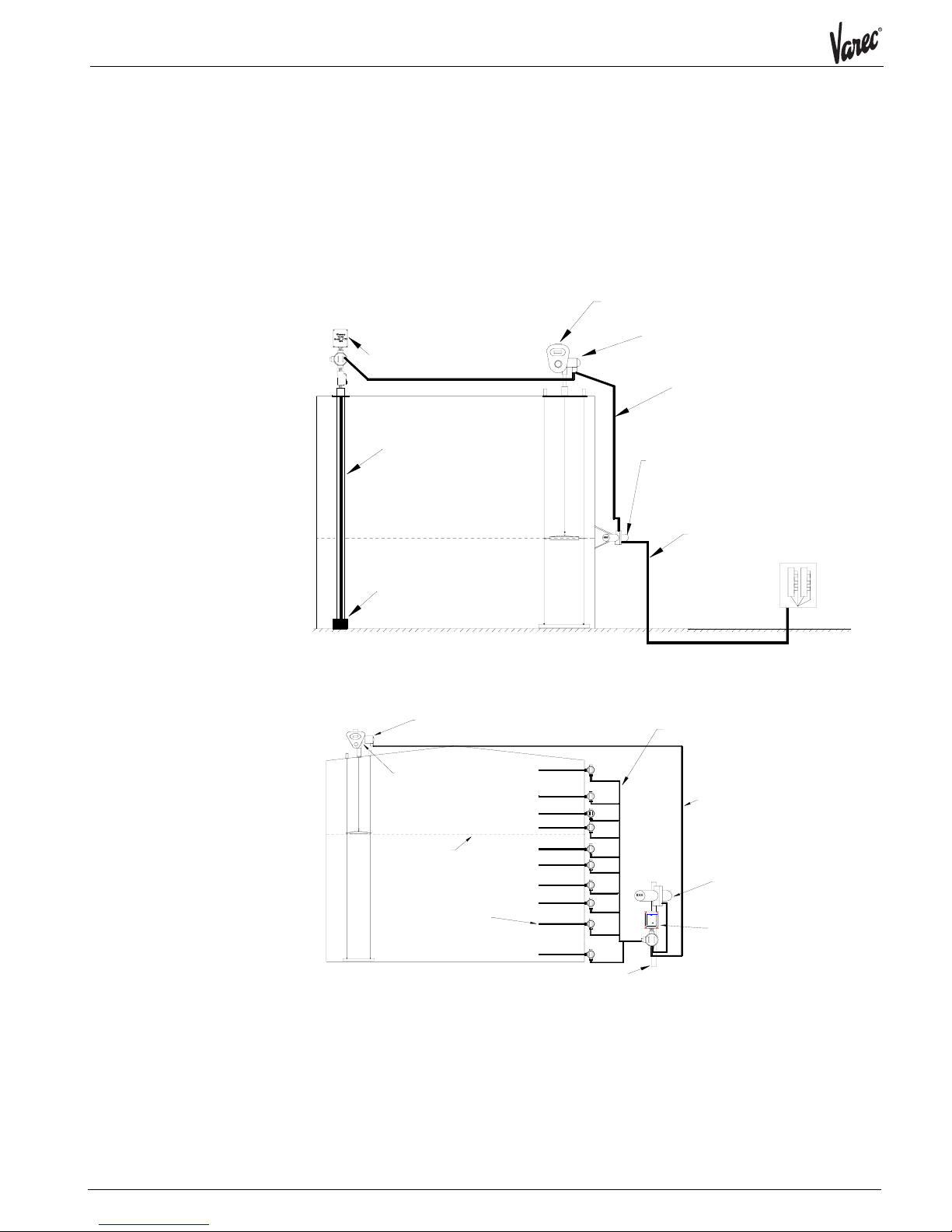
Figure 1 Typical Model 4120 Installation with Averaging Bulb . . . . . . . . . . . . . . . . . . . . . . . . . . . . . . . . . .8
Figure 2 Typical Model 4120 Installation with Multiple Spot Bulbs . . . . . . . . . . . . . . . . . . . . . . . . . . . . . . .8
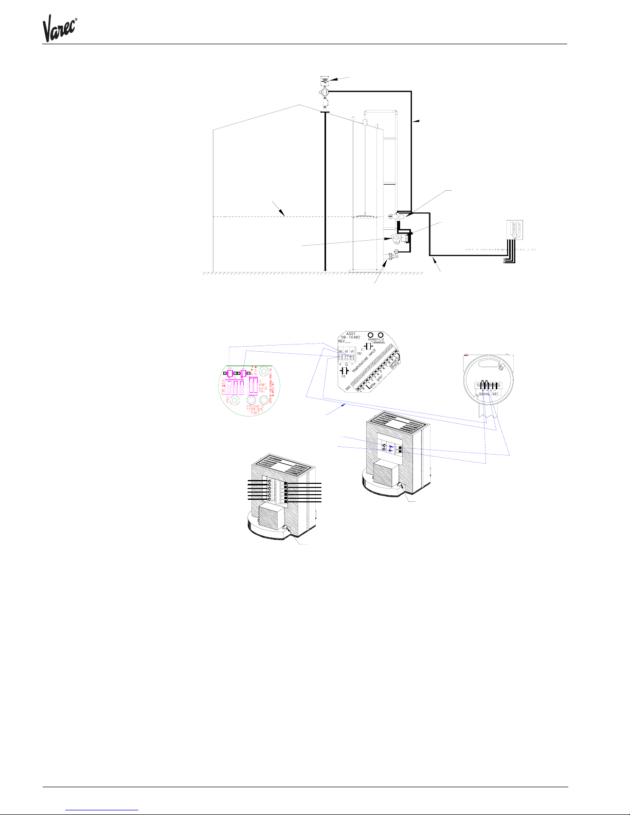
Figure 3 Typical Model 4120 Installation with Hybrid Gauging System . . . . . . . . . . . . . . . . . . . . . . . . . . . 9
Figure 4 Typical MFT/HART Host Communication Wiring . . . . . . . . . . . . . . . . . . . . . . . . . . . . . . . . . . . . . 9
Figure 5 Typical Average Bulb Wiring. . . . . . . . . . . . . . . . . . . . . . . . . . . . . . . . . . . . . . . . . . . . . . . . . . . . 10
Figure 6 Typical Multiple RTD Wiring . . . . . . . . . . . . . . . . . . . . . . . . . . . . . . . . . . . . . . . . . . . . . . . . . . . . 10
Figure 6 Dimensional Outline . . . . . . . . . . . . . . . . . . . . . . . . . . . . . . . . . . . . . . . . . . . . . . . . . . . . . . . . . . 10
Figure 8 Model 4120 Component Identification . . . . . . . . . . . . . . . . . . . . . . . . . . . . . . . . . . . . . . . . . . . . 16

IOM006GVAE1103 6
4120

Multi-Element Temperature Transmitter
7 Installation and Operations Maunual
Section 1 - Introduction and Installation
Using This Manual This manual describes the operation and usage of the Varec Model 4120 Multi-Element
Temperature Transmitter.
•Section 1 - Introduction and Installation
•Section 2 - Operation
•Section 3 - Specifications and Reference Data
•Section 4 - MFT/HIU and TankView Support for the METT
•Section 5 - HART Protocol Implementation
Getting Acquainted
with the Multi-Element
Temperature
Transmitter (METT)
The Varec Model 4120 Multi-Element Temperature Transmitter is designed for use with
two types of tank temperature configurations.
•Multiple Averaging Temperature Bulb
•Multiple RTDs
The first configuration uses a multiple averaging element temperature bulb and is
shown in Figure 1. Up to 10 elements are supported. Additionally, it has the capability
to acquire temperature from top and bottom spot elements. The top spot element is
used to measure the temperature of vapor space. In the averaging configuration the top
and bottom probes are expected to be part of the averaging temperature bulb assembly.
All temperature inputs are single wire with two common returns for all elements.
The second configuration uses multiple RTDs and is shown in Figure 2. The RTDs are
mounted at different heights on the side of the tank. Up to 12 RTDs are supported. All
RTDs must be of the 3-wire type and must all be of the same type. That is, they must
all be copper or platinum but not a mix.
The METT converts the resistance values to engineering units and transmits the
information over the HART bus. It is designed for use with the Varec Model 4100
Multifunction Transmitter, Model 4200 Hydrostatic Interface Unit or any other HART
host. The ATTI version is designed to operate with the Varec Model 4000 Advanced
Technology Transmitter.

IOM006GVAE1103 8
4120
Installation The Varec Model 4120 Multi-Element Temperature Transmitter is housed in a NEMA 4X
enclosure and is designed to meet FM, CSA, and CENELEC intrinsically safe approvals.
The METT mounts directly to a standard (API 2543) averaging temperature bulb such as
the Varec Model 9909. A junction box is included with terminal connections for the
averaging bulb wires, the Handheld Interface, and the HART bus. The METT provides
galvanic isolation and lightning protection between the HART bus and the temperature
elements. A larger terminal box is included with three terminals for each RTD
(maximum 30).
The ATTI bus version of the METT requires intrinsic safety barriers installed within a
junction box because the ATTI bus is not intrinsically safe.
Figure 1 Typical Model 4120 Installation with Averaging Bulb
Figure 2 Typical Model 4120 Installation with Multiple Spot Bulbs
Model 4110 HART Level Encoder
Model 2500 Tank Gauge
Bottom Weight
Model 9909 Averaging
Temperature Bulb
Model 4120 Multi-Element
Temperature Transmitter
Model 4100/4200
MFT or HIU
Four conductor cable
Mark/Space or EIA485
and DC power
to control room
Two conductor HART cable
intrinsically safe
Model 2500 Tank Gauge
Three conductor RTD cable.
One cable per RTD.
Model 4110
HART Level Encoder
Model 8500
Spot Temperature Bulb
three wire RTD
or equal up to 10 places
Model 4120
Multi-Element Temperature
Transmitter
Two wire HART cable
intrinsically safe
Model 4100
Multifunction Transmitter
Product level
Two inch mounting pipe
SERIALNO.
MODEL4120
WHESSOE
VAREC
MULTI-ELEMENTTEMPERATURE

Multi-Element Temperature Transmitter
9 Installation and Operations Manual
Figure 3 Typical Model 4120 Installation with Hybrid Gauging System
Figure 4 Typical MFT/HART Host Communication Wiring
Model 4120 Multi-Element Temperature Transmitter
Model 2500 Tank Gauge
Hydrostatic Pressure Transmitter
Product level
Model 4110
HART Level Encoder
Model 4200
Hydrostatic Interface Unit
Four conductor cable
Mark/Space or EIA485
to control room
To other tanks
Two conductor HART cable
intrinsically safe
Model 4100/4200
termination block
HART "+"
HART "-"
Ground Connection
STATUS-1 INPUT -5
STATUS-2 INPUT -6
COMMON (B-) -1
MARK/EIA485 "+" -3
SPACE/EIA485 "-" -4
B+ INPUT -2
10- RTD: B-LEAD
11- RTD: A-LEAD
12- STATUS COM.
8- 4-20 mA "-" Return
7- 4-20 mA "+" Source
9- RTD: C-LEAD
2 wire IS HART cable
shielded 18 AWG
LE
Model 4110
Ground Connection
Pressure Transmitter
Model 340F
METT
Model 4120

IOM006GVAE1103 10
4120
Figure 5 Typical Average Bulb Wiring
Figure 6 Typical Multiple RTD Wiring
TB2
CB
Colors shown for Whessoe Varec Model 9909
Averaging Temperature Bulb
Black
Black
Bottom Spot
3' Brown
5' Red
7' Orange
10' Yellow
14' Green
20' Blue
26' Violet
32' Gray
40' White
50' Pink
Vapor Space Spot
TEMPERATUREINPUT
ASSY
08--10482
REV_____
X2
+ G --
TB1
1234567891
0
BTM.SPOTVAPOR
SPACE
HANDHELD
TERMINAL
X1
Pins----RTD
TB2
1-3---1 ABC
4-6---2 ABC
7-9---3 ABC
10----4 A
TB3
1-2---4 BC
3-5---5 ABC
6-8---6 ABC
9-10-7 AB
TB4
1-2----7 C
2-4----8 ABC
5-7----9 ABC
8-10--10 ABC

Multi-Element Temperature Transmitter
11 Installation and Operations Manual
Figure 7 Model 4120 Dimensional Outline
2.180"
5.250"
4.000"
6.000"
MULTI-ELEMENT TEMPERATURE
SERIAL NO.
MODEL 4120
WHESSOE
VAREC
4.500"
12.817"
HANDHELD
TERMINAL
TEMPERATUREINPUT
ASSY
08--10482
REV_____
3/4 inch conduit entry
TB2
X2
+ G --
BTM.SPOT
CB
VAPOR
SPACE
1234567891
0
X1
TB1

IOM006GVAE1103 12
4120
Section 2 - Operation
The functional blocks of the Varec Model 4120 Multi-Element Temperature Transmitter
are described below.
Temperature
Configurations
The METT handles three temperature system configurations as follows.
API Averaging Bulb. API standard 2543 is used. An API averaging bulb has elements at
3', 5', 7', 10', 14', 20', 26', 32', and 40' for a 50' tank. For levels below 3', a spot probe
is expected at the 2'. The standard specifies that non-merchantable product should be
kept at least 1' below spot probe. The METT handles the bottom spot and a top spot for
vapor space temperature measurement.
Non-API Averaging Bulb. This is a multiple-spot system which consists of up to 10
averaging RTD elements. The elements may be of non-standard lengths. The length of
each element is configurable. Top and bottom spot temperatures are supported as
above.
Multiple Spot. A multiple-spot system can consist of up to 12 3-wire RTDs. The height
of each RTD is configurable. The first 11 can be averaged. The last spot is used as the
top spot for vapor space temperature measurement.
Temperature Averaging Averaging of the temperature depends on the type of temperature configuration being
used. For averaging bulb configuration, the METT reads the longest immersed element
and reports its temperature. The top probe is never used for averaging.
For multiple spot configuration, the METT reads all immersed elements and averages all
readings. For simplicity, spot temperatures are averaged given equal weight to all
immersed probes. The top probe is never used for averaging.
A host computer can read all temperature inputs via the HART protocol. Assuming the
host knows the level and has the temperature configuration in its database, it can then
calculate the average temperature. A host computer is also able to periodically write the
current level and read back the average temperature. This method is preferred since the
METT contains all the configuration information.
HART Communications
Interface
The METT communicates to a host system via the HART communication protocol. The
HART protocol allows the average temperature, temperature, and resistance to be read.
It also allows the current level and configuration information to be sent to the METT.

Multi-Element Temperature Transmitter
13 Installation and Operations Manual
Varec
Handheld Terminal
Interface
To support non-host configuration, the METT supports the Model 1200 Varec Handheld
Interface. The Rosemount Model 268 may be used if available. The METT supports the
ASCII interface in a similar manner to the Varec Model 4110 HART Level Encoder (LE).
That is, it answers to two different HART addresses. The first address is its address for
normal operation. The second address is the ASCII terminal address. The LE uses
address 15 for this. The METT will use HART address 14 to allow for tandem operation
with the LE in an MFT system.
To communicate with the METT using the Varec Handheld Interface, perform the
following steps:
•1.Make sure the Handheld Interface is not connected to the HART bus.
•2.Turn the Handheld Interface off and then on. It will first go through its self-test, then
try to communicate to a HART sensor at address 0. It will fail and display a warning
message, "Xmtr/268 not in communication".
•3.Press F2 to select multi-drop mode.
•4.Press F2 to select the address to communicate to.
•5.Press F2 twice to select address 14 and press F4 to start communication.
•6.The METT will clear the screen and place the cursor at the upper left corner.
•7.Pressing any key causes the METT to display the version number and ask if you want
display or alter mode. Press 'D' followed by F4 for display mode or 'A' followed by F4
to select alter mode.
•8.The F1 - F4 function keys have pre-defined functions. F1 is up, F2 is down, F3 is
modify/backspace, and F4 is the enter key. The 'Previous Function' key can be used to
abort modification of a variable or go up a menu level.
It is important to note that modifications done in Alter Mode do not take effect unless
'Exit and Save" is selected. This will cause the modifications to be saved to EEPROM and
used. If you disconnect the Handheld Interface or select the 'Quit' command, any
modifications that were made will be lost.
The menu interface is organized in a multi-level menu structure starting with the
Main Menu.
Main Menu Decription
Average Temperature1Average Temperature. Only valid if host, such as MFT, has been
writing the level to the METT.
Level1Last level written to METT. This can be manually entered to
observe the effect of different levels.
Config Menu Contains METT configuration menu items. See table below.
Diagnostic Menu1Contains METT diagnostic menu items. See table below.
Exit and Save2Must be used to exit the Alter Mode if configuration data modified
are to be entered.
Quit/Exit Used to quit Alter Mode without saving. Also displayed as Exit in
display mode.

IOM006GVAE1103 14
4120
Configuration Menu Decription
HART Address METT's short address on HART bus. Set to 5 to use with MFT.
Address 14 is reserved for Handheld Interface dumb terminal
mode. (0-13 and 15 are valid)
Serial Number Used for long address in multi-drop HART. Usually set at the
factory. If problems communicating, try setting to same as HART
address above.
Temp Units Temperature units used for display. Use F2/F3 keys select.
Level Units Level units used for display. Use F2/F3 keys to select.
Damping Value Amount of damping. (0-16 is valid. 0 is minimal damping, 16 is
maximum damping)
Noise Reject Type of noise rejection. 50 Hz/60 Hz are valid. Use F2/F3 keys to
select.
Temp Type: API Avg
Bulb/Avg Bulb/Multi-
Spot
Type of temperature system connected. API Avg Bulb/Avg Bulb/
Multi-Spot are valid. Use F2/F3 keys to select.
Temp Element Type Type of temperature element used. Can be copper or platinum.
Use F2/F3 keys to select.
Bottom Probe Type
None/Installed
Indicates if bottom probe is installed. Use F2/F3 keys to select.
Bottom Probe Height Height of installed bottom probe.
Top Probe Type: None/
Installed
Indicates if top probe is installed. Use F2/F3 keys to select.
Top Probe Height Height of top probe.
Temp Elements Number of temperature elements attached. (1 - 10 is valid)
Element 1 Height Height/Length of element. The heights are ignored and over-
written if API average bulb is configured.
Element 2 Height .
Element 3 Height .
Element 4 Height .
Element 5 Height .
Element 6 Height .
Element 7 Height .
Element 8 Height .
Element 9 Height .
Element 10 Height .
HART Variable 1 Type Parameter to be returned as the first HART PV. Use F2/F3 to
select. No configuration required if used with Varec's MFT.
HART Variable 2 Type Same as above for the second HART PV.
HART Variable 3 Type Same as above for the third HART PV.
HART Variable 4 Type Same as above for the fourth HART PV.

Multi-Element Temperature Transmitter
15 Installation and Operations Manual
1 Only displayed if in Display Mode
2Only displayed if in Alter Mode
3Only displayed if TRUE
Diagnostics Menu Description
Bad EEPROM3EEPROM holding the configuration data could not be written to.
Bad EE Cksum3EEPROM configuration data's checksum is bad. Review all
configuration data and perform an Exit and Save.
Bad RAM3RAM chip is bad.
Bad EPROM3Program memory is bad.
HART Polls3Number of HART polls received since power-up/new configuration
write. (0-65535 and resets to 0 after full value)
HART Errors3Number of HART communication errors encountered since power-
up/new configuration write. (0-65535 and resets to 0 after full
value)
Bottom Temperature Temperature at bottom probe
Temperature 1 Temperature at probe number 1
Temperature 2 Temperature at probe number 2
Temperature 3 Temperature at probe number 3
Temperature 4 Temperature at probe number 4
Temperature 5 Temperature at probe number 5
Temperature 6 Temperature at probe number 6
Temperature 7 Temperature at probe number 7
Temperature 8 Temperature at probe number 8
Temperature 9 Temperature at probe number 9
Temperature 10 Temperature at probe number 10
Top Temperature Temperature at top probe.

IOM006GVAE1103 16
4120
Figure 8 Model 4120 Component Identification
Item Description Part Number
1 NEMA 4X Enclosure 15-10727
2 Conduit Box P109-18-014
3 METT Terminal PCB Avg. Bulb 08-10482
Not shown METT Terminal PCB RTD 08-10747
4 Nipple Assembly
5 Conduit Entry P109-16-009
6 METT CPU PCB 08-10494
7 Standoff P102-21-085
8 Screw 10-32 P031-06-1805
9 Label varies
10 4120 Harness Assembly 02-10726
11 Screw 6-32 P31-824
1234567891
HANDHELD
TERMINAL
BTM.SPOT
TB2
CB
TEMPERATUREINPUT
X2
+ G --
X1
TB1
ASSY
08--10482
REV_____
VAPOR
SPACE
0
WHESSOE
VAREC
SERIAL NO.
MULTIPLE ELEMENT TEMPERATURE
MODEL 4120

Multi-Element Temperature Transmitter
17 Installation and Operations Manual
Section 3 - Specifications and Reference Data
Specifications and
Physical
The following specifications apply to the Varec Model 4120 Multi-Element Temperature
Transmitter assembly over the operating temperature range.
Functional RTD Inputs Supported 100 Ohm Copper, 100 Ohm Platinum Characterized
Copper and
100 Ohm Platinum (DIN)
Input Voltage 15 to 65 VDC
Operating Current 4 mA Constant Current
Accuracy +/- 0.5 oF (+/- 0.25 oC)
Hazardous Location
Approvals
Designed to meet FM, CSA, and CENELEC intrinsically safe approvals for
Class 1, Division 1 Groups B and C.
(Consult factory for approval status.)
Environmental Operating Temperature -40 oC to +85 oC
Storage Temperature -40 oC to +85 oC
Transient Lightning Meets ANSII/IEEE C62.41
Humidity 0 to 100%
Enclosure NEMA 4X, Fiber Reinforced Resin
Performance Accuracy, repeatability and sensitivity per American Petroleum Institute Manual
of Petroleum Measurement Standards, Chapter 7, Section 7.4, fourth draft,
December 3, 1990.
Physical Shipping Weight 6 lb. (3 kg)

IOM006GVAE1103 18
4120
Model Options
Model Description
4120 Multi-Element Temperature Transmitter
Code Bulb Type
AB Averaging Bulb
MS* Multiple Spot Bulb
Code Bulb Type
HA HART
AT* ATT - For use with Varec Model 400
Code Approvals
00 No Approval
FM Factory Mutual (FM)
CS Canadian Standard Asscociation (CSA)
CE CENELEC
ÈÈÈÈ
4120 AB HA 00 Sample Ordering No: Multi-Element Temperature
Transmitter with Averaging Bulb, HART Bus, and No
Approvals
* Consult Factory

Multi-Element Temperature Transmitter
19 Installation and Operations Manual
Section 4 - MFT/HIU and TankView Support for the METT
MFT/HIU Support Model 4100 Multi Function Transmitter (MFT) and Model 4200 Hydrostatic Interface Unit
(HIU) versions 1.6 and above include specific support for the METT.
•The MFT allows setting of the METT's HART address. It will expect it to be at address
5. This is the same address as the Rosemount 3044.
•A temperature selection of METT must be specified to the MFT under TEMP TYPE item
located in the Sensor Configuration menu.
•If METT is the temperature sensor, the MFT periodically writes the level to it and reads
the average temperature from it. Additionally, the MFT also reads all 12 temperature
values from the METT and map those values into its MODBUS register. This allows a
host computer to read all 12 values.
•The MFT does not duplicate all the configuration menus of the METT. The MFT expects
the METT to have been configured for the desired temperature system .
TankView Support The current TankView support for the METT is minimal. It basically allows the METT
temperature type to be entered to tell the MFT the type of temperature device it is
connected to.
Table of contents
Other Varec Transmitter manuals