VAS PS21 User manual


ATTENTION!!! SCHOCK HAZARD!!!
DO NOT ACTIVATE WITHOUT GROUNDING!!!
Table of contents
1 Purpose of VAS-PS21 .................................................................................................2
2 Technical characteristics..............................................................................................2
3 Description...................................................................................................................3
4 Warranty ......................................................................................................................6
5 Appendixes ..................................................................................................................7
1 Purpose of VAS-Power Supply
Power supply unit VAS-PS21 is created to supply backup low voltage (12V and 24V) to
power amplifiers and other equipment of Public Address and Evacuation management system.
Unit also may be used to supply power to emergency light system, other technical
systems such as light emergency signs, electromagnetic locks of emergency exits, siren
generators etc.
Unit complies with EN54-16:2008 and EMC Directive 2004/108/EC which is confirmed
by relevant papers.
All units have a built-in battery, charging and battery control system with indication of
condition of battery and circuit voltage, nonswitched DC outputs for 12V and 24V, switched DC
for 24V and switched 220V AC.
2 Technical characteristics
Parameters
PS-21
Main power
220V AC/ 50Hz
Max current consumption from main power circuit
1.5A
Type / Voltage / Capacity of built-in batteries
AGM / 12V / 7Ah
Number of built-in batteries
6
Capacity of built-in batteries (for 24V output)
21Ah
Battery LED light up threshold
22V
PS outputs number and parameters:

Constant voltage / Max current on nonswitced +24V
output
24-28V / 2A
Constant voltage / Max current on nonswitced +12V
output
12.2-12.6V / 2A
Constant voltage on switched output +24V
24-28V
Max constant current on switched output +24V
21A
Size (W/H/В)
3U (480/144/433)mm
Weight not more than
24kg
3 Description
3.1 Description of Power Supply unit.
Power Supply unit distribute power to any components of Public Address and Evacuation
management system which are calculated to supply from 12/24V unstabilized power.
Voltage change limit on 24V output with current 2A is from 24 to 28V.
Voltage change limit on 12V output with current 2A is from 12,2 to 12,6V.
When unit is supplying from 220V AC main circuit the total available power of
nonswitched outputs for 12V and 24V is 70W. In case of circuit voltage raise to 230V the total
available power will decrease to 60W. In case of circuit voltage raise higher than 230V the total
available power will decrease to 50W.
In case of excess above limits electric protection may switch off the outputs.
When unit is supplying by built-in batteries it can distribute following current from
powerful switched 24V output:
21A for VAS-PS-21
Unit has built-in battery charging and condition control system, as well as temperature
controller of each battery.
Attention! Backup output current should not exceed mentioned numbers, to supply
nominal charging regime.
Power Supply unit has two built-in relays to expand system capabilities. It allows to
commutate voltage to some loads such as amplifiers, evacuation light signs, electromagnetic
door locks etc.).
3.2 Structural diagram of the unit is shown of pic.1. Unit consist of following
components: Power supply and battery charging module, maintenance-free battery, control and
indication module, output voltage commutation relays.

Pic.1 Structural diagram.
24V Output control input is calculated on 24V and located on the rear panel of the unit.
220V output control input is calculated on 220V and located on the rear panel of the unit as euro
socket.
3.3 Controls and indication located on the front panel description.
The appearance of the unit is shown on the pic. 2
There are following items located on the front panel:
1. ON/OFF button
2. Power LED. In case of power on and main voltage of 220V is it lights green.
In case of 220V loss it lights red.
3. Batteries (Accumulator) Discharge LED lights yellow in case of battery
voltage drop less than normal value (21-22V). This LED signalize of necessity
of charge batteries. If continue to work without main power and batteries
voltage drop less than 20.5V, the unit will beep for attention, than turn off.
4. Batteries (Accumulator) Failure LED lights up in case of batteries failure.
Need to change batteries.
Pic.2 Appearance of the unit.
3.4 Back panel inputs and outputs description.
Back panel appearance is shown on the pic. 3.

Pic 3 Back panel appearance.
The following items are located on the back panel:
1. “Power for amplifier 24V” –the main switchable 24V…28V Output for amplifier
backup supply. The 24V voltage appears on this output in case of 2 events. Power
switch is turned on, and 24V comes to the “Control Commutation Output” clamp.
2. “Input 220V from Control Unit” is to control the switchable 220V output.
3. “Output 220V to another supply unit” is to connect the control voltage to the next
power supply unit. ATTENTION! This output is calculated for small current. It is
strictly prohibited to connect power amplifier to this socket.
4. Fuse 220V, 2A
5. “Power to amplifier 220V” socket is switchable 220V socket for power supply to
amplifier.
6. “220V 2A” Socket is to connect the unit to the main power circuit 220V.
7. “Ground” clamp is for protection grounding.
8, 9, 10. “Battery 1”, Battery 2”, “Battery 3” is for installation of protective fuses for each
of three pairs of batteries.
11. Multifunctional terminal block. It consist following contacts:
“24V control input”
Nonswitchable outputs 12V, 2A and 24V, 2A
Open collector type Failure output. Close to the ground in case of main power loss
or battery failure.
Open collector type Start output. Close to the ground in case of voltage supply to
switchable 24V and/or 220V outputs.
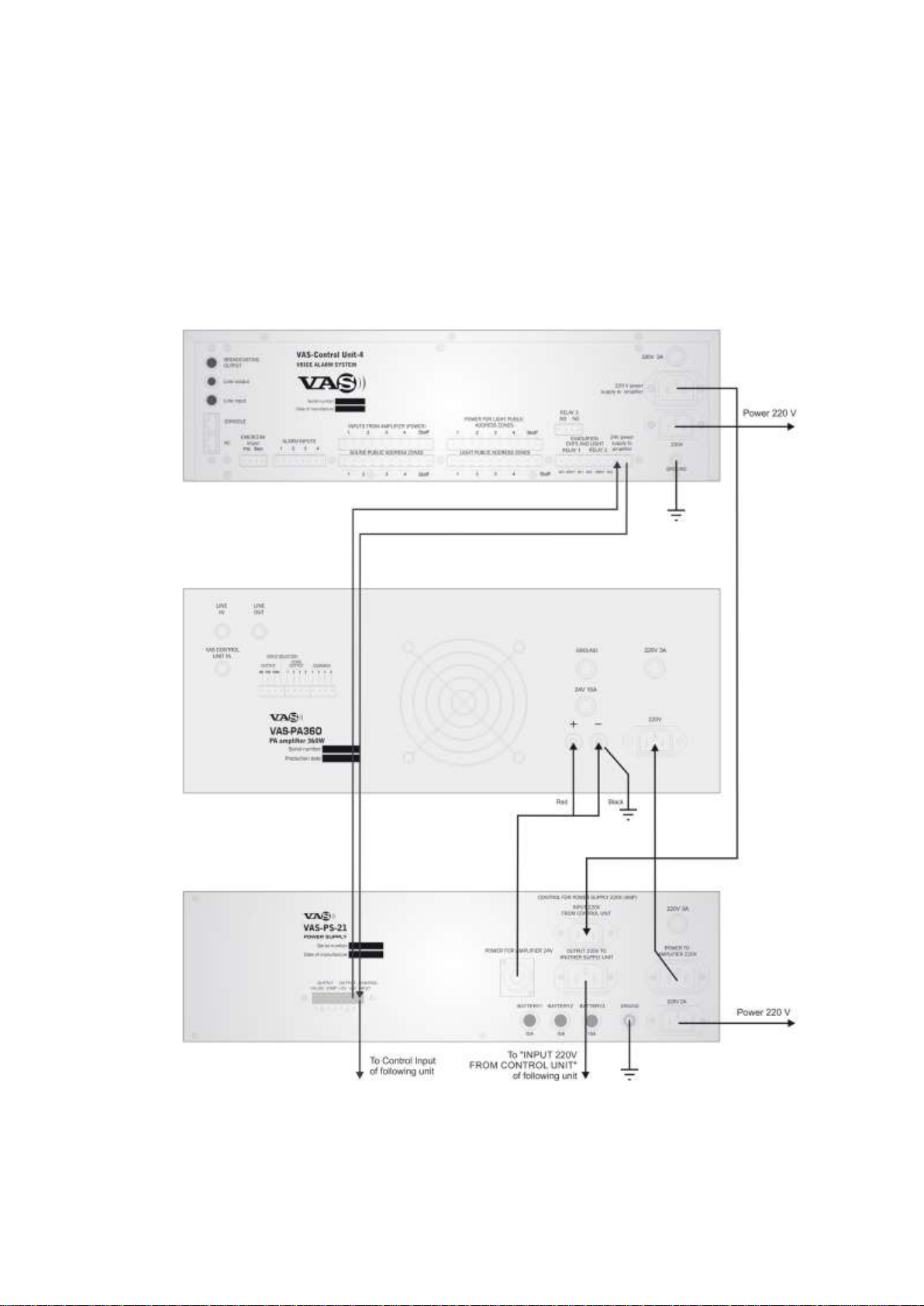
Typical connection diagrams of power supply unit “VAS-PS-XX” as part of Public Address and
Evacuation management system are shown on appendixes 1-5.

Attention! All cables for grounding and connection of backup power 24-30V using in
diagrams shown below must be calculated to corresponded current.
We recommend to use cables in thermo proof isolation with following cable cross-
section: not less than 2.5 mm2for VAS-PS-21.
4 Warranty
Warranty period for the device is 24 months from the moment of sale.
During a warranty period the owner has the right for free repairs of a product at if he produces
the guarantee filled properly.
Warranty is not extended to a product, which has the broken seals, mechanical damages, or signs
of misuse.
Warranty and after warranty repairs are carried out only by the enterprise-manufacturer.
Expenses of the owner for delivery of a product to a place of warranty repair are not
compensated.
Manufacturer
VAS Tronics
4210, OfficeTower, Convention Plaza, 1 Harbour Road, Wanchai, Hong Kong
www.vastronics.com
5 Appendixes
Appendix 1
One or several power amplifiers main and backup power control
diagram.

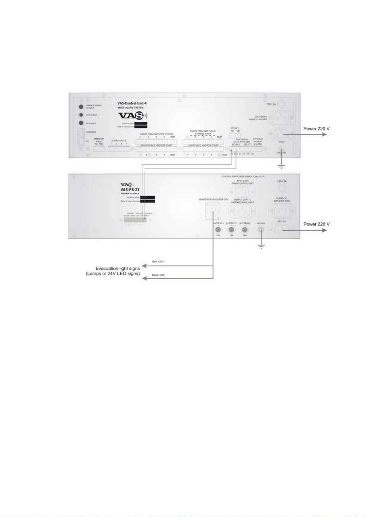
Appendix 2
24V light signs connection diagram

Appendix 3
24V evacuation light connection
diagram
Appendix 3
24V evacuation light connection diagram (var. 2)
Table of contents


