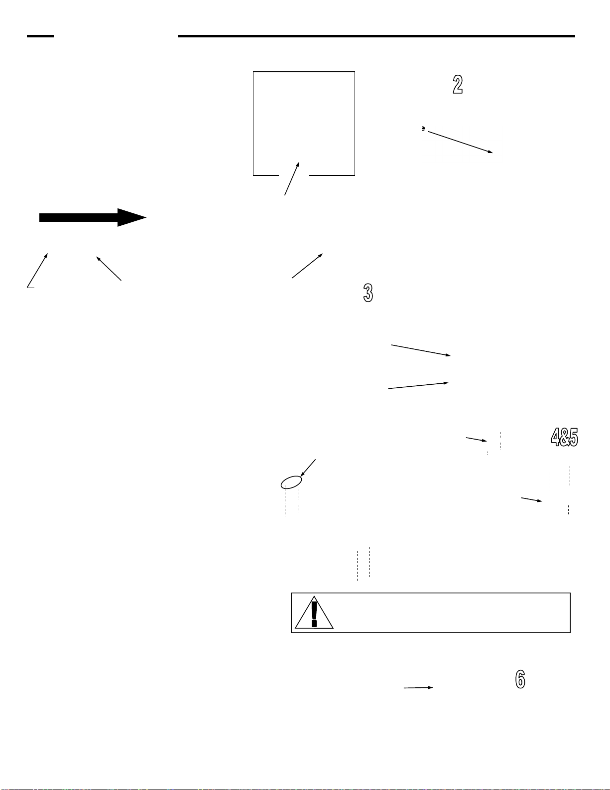
VASTEX LittleRed-X Series User manual

LittleRed-X Series Dryers
Assembly, Operating, and Maintenance Instructions
LittleRed-X Series Dryers (X1/X1D/X2/X2D/X3/X3D)
Serial Number:
(Please log your machine's serial number and date of purchase for future reference.)
Date:____/____/______
Electrical Drawing #: Rev:______
Doc. # 01-28-001M
VTX
Vastex E-mail assistance
Purchasing & Product Info:
Electrical Support:
stech@vastex.com
Tech Support, Mechanical Setup, and Operation:
techsupport@vastex.com
Original Instructions
Vastex International, Inc.
7 Emery St
Bethlehem, Pa. 18015-1982 USA
Phone# 610 625-2702 Fax# 610 625-2775
Web Site www.vastex.com
Authorized Representative in Europe:
Certification Experts BV
Nieuwstad 100 1381 CE Weesp,
The Netherlands
Tel : + 31 (0) 294 – 48 33 55
Fax : + 31 (0) 294 – 41 46 87
Year of Manufacture:
Contents Page#
Introduction / Safety 2-3
Assembly 4-7
Electrical Hookup 6
Component Identification 8
Controls 9
Controls / Zone Information 10
Operation 11-12
Exhaust 13
Maintenance 14
Troubleshooting 15
Speed Adjustments 16-17
Conveyor Details 18
Ducting Information 19
Warranty / Terms & Conditions 20

The Instruction Manual and Safety Instructions must be read and understood by anyone
operating the Vastex Conveyor Curing System.
The operator should read and understand the instruction manual before operating this equipment. Store instruc-
tion manual and safety instructions near equipment for easy access to operators.
VASTEX Conveyor Curing System is intended for the curing of non-flammable inks on screen printed materials.
Do not use for any other purpose unless authorized by Vastex International, Inc. Use of this equipment for any
other purpose can be dangerous and may cause damage to this equipment, voiding the warranty.
It is recommended that the area around this equipment be designated as a work area and only authorized em-
ployees be allowed in the area.
Children and pets must be kept clear of the work area.
Do not place any objects on top of the drying chamber. Surfaces are hot!
Never leave equipment unattended.
Do not operate conveyor or dryer with any cover or guard removed.
Operator must be familiar with controls of the dryer and conveyor.
Never put excessive load on the conveyor belt.
Before starting production, the operator must check that all covers and guards are in place, no material has been
left on the conveyor, and the work area is clear of obstructions.
Switch on and verify conveyor belt is moving before turning on the heat.
Allow dryer to cool to 300°F (149°C) before switching off conveyor.
Always turn off power at the main disconnect at the end of production.
In case an abnormal symptom occurs, for example excessive vibration, noise, and strong smell or smoke devel-
opment, turn off the VASTEX Conveyor Curing System and contact a qualified technician.
Immediately turn off the VASTEX Conveyor Curing System if products become jammed in the drying chamber or
conveyor belt.
Do not remove any cover or guard until power at the main disconnect is switched off and locked out. No unau-
thorized persons are to be allowed inside the control boxes.
Turn off and lock out power at the main disconnect before any cleaning or maintenance.
Only qualified technicians should be allowed to make repairs on the VASTEX Conveyor Curing System.
Noise and vibration: This equipment does not produce noise exceeding 70 dB(A) at workstations.
Operating Temperature: Vastex Equipment should not be operated in temperatures below 40°F(5°C) or
above 105°F(41°C)
Stability during use, transportation, assembly, dismantling when out of service, testing, and foreseeable
breakdowns: This equipment is designed and expected to be stable during all foreseeable conditions, so long
as the procedures and instructions given in this manual are followed.
Congratulations, you have chosen a VASTEX conveyor curing system. VASTEX has been designing and building
dryers since 1960 and has the knowledge and expertise to supply a quality dryer and help you keep it running for
years to come. VASTEX has innovated many of the features found in conveyor ovens today from control methods,
modular features, air movements and belt tracking.
Your Vastex Infrared Dryer has been Factory tested and burned in for a period of 2-8 hours. All components are
tested to be sure they work correctly when the Dryer leaves our factory.
Introduction
Safety
Pg. 2

Safe handling, transport, and storage: Before storing the unit, follow the shutdown procedure on P. 9
(or on the front of your machine) to allow the heater assembly to cool properly. No special handling con-
siderations are necessary, except to be aware of the weight of the equipment and take standard precau-
tions for moving such weights:
LittleRed-X1D-18: 172 lbs (78kg), 47.5” x 28” x 50” (121 cm x 72.3cm x 127 cm)
LittleRed-X1-30: 172 lbs (78 kg), 47.5” x 40” x 46” (121 cm x 102 cm x 117 cm)
LittleRed-X1D-30: 220 lbs (100 kg), 47.5” x 40” x 46” (121 cm x 102 cm x 117 cm)
LittleRed-X1-54: 380 lbs (172 kg), 65.5” x 65” x 50” (166 cm x 165 cm x 127 cm)
LittleRed-X2-30: 304 lbs (138 kg), 83.5” x 40” x 48” (212 cm x 102 cm x 122 cm)
LittleRed-X2-54: 480 lbs (218 kg), 83.5” x 65” x 50” (212 cm x 165 cm x 127 cm)
LittleRed-X2D-30: 304 lbs (138 kg), 65.5” x 40” x 50” (166 cm x 102 cm x 127 cm)
LittleRed-X3-30: 420 lb (191 kg), 87.5” x 40” x 50” (222 cm x 102 cm x 127 cm)
LittleRed-X3-54: 700 lb (318 kg), 87.5” x 65” x 50” (222 cm x 165 cm x 127 cm)
LittleRed-X3D-30: 420 lb (191 kg), 87.5” x 40” x 50” (222 cm x 102 cm x 127 cm)
LittleRed-X3D-54: 700 lb (318 kg), 87.5” x 65” x 50” (222 cm x 165 cm x 127 cm)
LittleRed-X3D-78 850 lb (386 kg), 102” x 88” x 54” (258 cm x 225 cm x 137 cm)
*** REMOVE THE CLEAR HEATER / SENSOR PROTECTOR SHEET BEFORE OPERATING THE DRYER ***
(protector sheet is located between the heater face and the sensor bracket)
At the end of all shifts and / or production runs, follow the Dryer Shutdown Procedure posted on the front of the dryer.
Any restriction in the dryer exhaust may result in excessive heat buildup within the chamber. Follow the Dryer & Exhaust
Hood Ducting directions in the manual.
Placing your equipment into service and using your machine:
To place your machine into service, follow steps 1-9 on pages 4 through 6.
To use your machine, follow the instructions on pages 11 and 12, after familiarizing yourself with the controls of
your machine (see pages 9 and 10).
Please read and understand all parts of this manual to avoid any Residual Risks.
Loose or dangling clothing may become entangled in the pulley. The pulleys are guarded against direct contact.
Your Vastex Infrared Dryer has high temperature heaters. There is an inherent danger when dealing with a heat
source of this degree. These heaters are often run at temperatures near 1,000° F(538° C). Any body part or item that
comes in direct contact with the heaters will be damaged. The heaters are guarded against direct contact from all
sides except the bottom.
The workspace that your Vastex Infrared Dryer occupies must be kept clean and clear of debris.
All sides of dryer must be reasonably accessible by the operator. A clear perimeter of 18” is preferred.
Do not store items, especially food or drink, on the top of your Vastex Infrared Dryer.
The room that you are operating your dryer in should be adequately ventilated. Please refer to the MSDS sheet of
the ink you are curing.
Important
Safety (cont’d)
Residual Risks
Workspace
Pg. 3

Tools Needed: (2) 9/16” open end wrenches, (1) 7/16” open end wrench or socket, (1) 1/4” nut driver OR flat blade screw driver
1b) Each conveyor has a pair of legs, a Front section,
Rear Section, and middle conveyor pieces. Bolt together
each section, as shown in the diagrams. Refer to Page 18
for each conveyor’s specific layout.
All parts are attached together using 3/8-16 x 3/4”
bolts, square washers and 3/8” serrated locknuts.
Assemble the Front Section, Rear Section, and mid-
dle conveyor pieces first.
Place assembled conveyor onto legs, attach using
3/8-16 x 3/4” Bolts and 3/8” Locknuts
Tighten all with 9/16” open end or socket.
Front
Section
Drive
Section
Assembly
Middle
Section
1a) For X1-30 and X1D only, the legs must be
assembled. Using (20) 10-32 Bolts and
(20) 10-32 Serrated nuts, assemble each
leg set as shown on right. Stock dryers
have 2 legs. Conveyor Extensions which
lengthen the conveyor to 10’+ should add
an additional leg per 3’ extension.
10-32 Bolt
10-32 Serrated Nut
Pg. 4

4) Install the chain guard with the (2) black #8
machine screws. Tighten with 1/4” nut driver.
See Maintenance section for chain adjust-
ment
5) Install the (3) Belt covers. Each uses (2)
black #8 Screws. Tighten with 1/4” nut driver.
Do not operate with Chain Guard removed.
Serious Injury may result!
6) Place the Heat Chamber on the conveyor, centered
between the belt’s rollers, with the Control Panel on
the right side.
2) The belt needs to be installed as shown in
the diagram. To connect your belt, align
the Alligator Lace and install the pin.
NOTE: If the pin walks out of the alligator
lace during use, pull the pin out about 1
inch add a kink to it and push the pin back
in.
Aligner
3) The belt needs to be tightened and ad-
justed. To tighten and adjust the belt, use
the Aligner Bolts. To raise the Aligner,
turn the Aligner Bolt clockwise with a
7/16” wrench. To lower it, turn it counter
clockwise. Raise the Aligner until you
have about 2”-2½” of slack as shown on
right. Additional details on PAGE 7.
Aligner Bolt
Belt Travel
Front Pulley Rear Pulley
Alligator lace
Chain Guard
Belt Cover
#8 Machine
Screws
Heat Chamber
Assembly (cont’d)
2a) For LittleReds
equipped with a drop
down motor and rear
idler, route the belt
above rear idler.
Rear Idler
(Optional)
Never tighten this nut!
Pg. 5

Motor
Threaded CPC connection
7) Have a licensed electrician complete the electrical hook-up and fill out the warranty card. Send it back to Vastex
to validate your warranty. A wiring diagram has been included with this manual and must be referenced to con-
nect this machine to power. If your machine has a plug installed from the factory, under no circumstances may
anyone other than a Vastex Employee modify the line cord or plug. Plug this into the correct wall socket with
dedicated breaker and appropriate sized wire. No extension cords may be used.
8) Plug the wire from the control box into the threaded cpc connector near gear motor. Shown below
9) Have a licensed electrician test the shops voltage at the machines disconnect, for shops with less than 240V service,
it is necessary to auto tune your controller. This procedure can be found in the Troubleshooting section.
Please record your shops actual voltage here:______________________
Review spec tag and wiring diagram for electrical requirements.
FLA refers to Full Load Amps, NOT the recommended line size.
A licensed electrician should perform electrical installation.
Please follow the NEC for wire selection and sizing.
Do NOT use solid or aluminum wiring for main power hookup.
All connections, especially power hookup, should be checked
and tightened after one month of operation
Ground
Assembly Electrical
Spec Tag
Motor CPC
Main Power
Feed
Pg. 6

Assembly (cont’d)
Belt Tracking
(Move in small increments while belt is moving. Do not leave
conveyor running unattended.)
If the belt is slipping, add belt tension by raising equally
both sides of aligner roller. 1”-2” of belt sag at the bottom side
is desirable. To raise roller turn adjustor bolt clockwise.
Belt moving to the left, raise left side of aligner by turning
aligner bolt clockwise 1/2 turn at a time.
Belt moving to the right, raise right side of aligner by turning
aligner bolt clockwise 1/2 turn at a time.
If belt is tracking off center at the drive roller, slightly loos-
en bearing bolts, (2) 1/2” wrenches needed. Turn adjustor
screw clockwise to move belt toward motor end of pulley and
counter clockwise to move belt away from motor end of pul-
ley, retighten all bolts. Recheck belt tracking at front end.
Note: Do not over-tighten belt. Final Belt tightness can be
gauged by the ability to stop the rear (drive) pulley
by applying a moderate force to the belt. Exceeding
your drive’s weight capacity should cause the belt to
slip before motor damage occurs.
Belt aligner pulley Aligner bolt
Conveyor Front End
Drive roller adjustor
Adjustor screw
Bearing bolts
Conveyor Rear End
DO NOT
TIGHTEN
NUT!
To move the belt to the Left
To move the belt to the Right
Turn bolt Clockwise,
Raising this side of
Aligner Roller
Turn bolt Counter Clockwise,
Lowering this side of Aligner
Roller
Turn bolt Counter Clockwise,
Lowering this side of Aligner
Roller
Turn bolt Clockwise,
Raising this side of
Aligner Roller
Never tighten this nut!
Pg. 7

Conveyor Components
IR Heater- w/ J Sensor Gear Motor
Belt
Belt Aligner
Front Pulley
Belt The conveyor belt is made of Teflon coated fiberglass. It is joined together with an alligator lace using a steel pin to connect each side.
The belt will not burn under normal conditions but the dryer should always have the belt moving while the heaters are above 300°F(149°
C). The belt should remain tracked in the center of each pulley. (See “Belt Installation and Tracking” for adjustment instructions.)
Aligner The aligner is a device for tracking the belt and keeping it on the pulley. As the belt moves from side to side the aligner is used for ad-
justments to keep it centered. The belt does not have to be perfectly centered on the pulley but should not be hanging over either edge.
LittleReds come standard with an aligner roller.
Pulley The pulleys at either end of the conveyor are made by VASTEX of 4 ½ inch tubing with ¾ inch center shaft. They are mounted on self
aligning flange bearing blocks for precision rolling.
Gear Motor A 90 or 130 Volt DC gear motor is located to the rear of the conveyor. It drives the rear pulley and belt with a roller and a #25chain
(standard drive) or #35chain(HD drive). Replacement part numbers can be found on the wiring diagram.
IR Heater The infrared heaters in VASTEX dryers emit medium wave infrared heat, perfect for curing many types of inks. The heater connections
are located in the trough on the right side of the heater, connected with high temperature terminals and stainless steel socket head cap
screws. (See Wiring Diagrams for Heater Specs)
J Sensor The sensor is mounted under the heating element, on the side closer to the control panel, with a shield beneath it. On X2 models, the
sensor is on the rear heater. The sensor is wired to the temperature controller using two wires, a red (positive) and a white (negative).
They must be attached to the proper terminals on the controller. Refer to wiring diagram when replacing “J” Sensor. (if SBER is dis-
played on controller “J” Sensor is malfunctioning)
Control Box The Control Box houses all the electrical components of the Dryer except the Drive motor. More information on the Control Box and
Control Panel found in section Controls.
Powered Powered exhaust removes fumes/moisture from the chamber. See Dryer & Exhaust Hood Ducting on pg19 for more information.
Exhaust Powered exhaust is standard on all LittleReds manufactured after May 2020
Chamber Components
Control Box
Powered Exhaust
Rear Pulley
(LR-X2-30 Shown)
Component Identification
Pg. 8

DC Volt Meter:
Digital Volt Meter displays, in
volts, the amount of power going
to the belt motor. A table showing
the time associated with voltage
can be found in Dryer Operation.
Belt Speed Control: An AC-DC
converter, mounted to the face of the
control panel, allows the operator to
vary the belt speed / DC volts to the
motor. The dial is for reference only and
does not represent seconds in the heat.
Control Output Light:
This light should cycle on & off
with the controller, indicating
output signal to relay.
(1 light per temp control)
System Switch:
Sends power to Controls.
Shut off power at main dis-
connect before servicing,
Power Light must be out be-
fore entering any part of this
machine
Power Light: It is wired to
the line cord and/or the Shut
Off Switch and will be
illuminated whenever power
is coming into the unit. At the
end of the day, the machine
should be disconnected so
this light is out.
Temperature Control:
See Dryer Operation
for more information
(1 control per zone)
Relay Output Light:
This 250 volt RED pilot light
is wired to the output side of
the relay. This light will cycle
on & off with the control
output light. It verifies that
the relay is working properly.
(1 light per relay)
Heat Switch:
Controls power
to heater only.
Controls (LittleRed X1/X2/X3)
Shut Off Switch
Machines that are direct wired by the end user are
equipped with a shutoff switch. This is the main junction
block for incoming power, and is used to restrict access
to the control box while it is live. The shutoff must be in
the OFF position to enter the control box.
Shut Off Switch:
Fuses:
Fuses for control circuit
are located on the face for
easy maintenance. Older
models have fuses located
inside the control box.
Please refer to wiring
diagram for fuse specs.
Heater Light:
This 6v WHITE pilot light is
wired to the IR Heaters. These
lights indicate when electricity
is flowing through each heater.
(1 light per heater)
Controls (LittleRed X1D-18)
Heat Switch: Main Heat Switch
controls power to heater.
Boost Zone Diagnostics:
The Boost Zone on your X1D is always
active. These 2 lights should stay on while
the Heat Switch is on and the Boost Zone
is functioning. BOOST mode runs the front
19% of the heater at 100% power to
preheat the garment on tunnel entry.
Pg. 9

Controls (LittleRed-X1D-30/X2D/X3D)
Controls between all LittleRed-X Models are similar. Refer to previous page for all unlisted controls.
BOOST Zone Temp Control:
Controls Temperature of Boost
Zone. Must be set to the same
temperature OR HIGHER than the
MAIN Temperature control.
MAIN Temp Control:
Controls Temperature of
MAIN heat zone.
Heat Switch:
Controls power to
BOTH heat zones
Zone Control X2D/X3D
Zone “BOOST”
Zone “BOOST” on your LittleRed X2D or X3D is controlled independently. This Zone is used to superheat your garments on the
way into the chamber. Typically, the longer your garment is in the chamber, the lower this BOOST zone can be set.
Setting the BOOST to 1100F+ is recommended for cure times at or below 60 seconds.
Setting the BOOST to 800F+ is recommended for cure times between 2 and 4 minutes
Zone “MAIN”
Zone “MAIN” on your LittleRed X2D or X3D is controlled independently. This Zone encompasses 85%(X2D) or 90%(X3D) of
your cure time. If you are running plastisol or other non-specialty items, you may set the BOOST and MAIN zones to the same
temp. The dryer will perform similar to other infrared dryers when BOOST and MAIN zones are set the same.
Setting the MAIN to 650F + is recommended for cure times at or below 60 seconds.
Setting the MAIN to 500F + is recommended for cure times between 2 and 4 minutes
BOOST ZONE TEMP CONTROL
BOOST ZONE DIAGNOSTICS
MAIN ZONE DIAGNOSTICS
Controls (LittleRed X3D-78)
MAIN ZONE TEMP CONTROL
BOOST ZONE TEMP CONTROL
Exhaust System Fault
Warning Lights:
These lights will flicker upon
startup as the fans reach
their full operating speed.
These lights MUST be off
during normal operation. If
either illuminates, there is
likely an obstruction in the
exhaust or a fan has failed.
Heat Switch:
Controls power to
BOTH heat zones
Heat Switch:
Controls power to
BOTH heat zones MAIN ZONE TEMP CONTROL
Pg. 10

Set the Belt Speed: Rotate the Belt Speed Control Knob clockwise to increase speed and counter-clockwise to
decrease it. Refer to the charts on the next page for “Time Through Chamber” settings. For
Plastisol inks, a good starting point is 20-25 seconds in the chamber.
Set the temperature: With the power on, push and hold the up arrow, the (SV) will climb. The longer you hold the
button, the faster the (SV) will climb, it will start climbing by one, then ten, then hundreds. Set
the desired temperature and allow approximately 15 minutes for heat up. Refer to the trouble
shooting section for Controller Error Messages.
Curing Plastisol with infrared:
Plastisol ink can fully cure in approximately 20-30* seconds. The ink must achieve 310°-320° F (154°-160°C) to cure and fuse to
the garment. We recommend* a starting temperature 800°F (400°C) , 3” heater height, and 25 seconds in the chamber.
Discharge or water based:
Water based products require more time than plastisol to cure due to the fact that the water/moisture must be evaporated before
the ink can cure. We have seen cure times from 50 to 90* seconds to achieve a full cure or discharge and not damage the gar-
ment. Please note as the time is increased the temperature must be decreased to protect the garment from scorching.
*Actual cure times can vary depending on conditions such as garment moisture and color, ink color, ink thickness, and
environmental conditions. All three variables should be used to maximize production while insuring a proper cure.
How to determine Temperature set point:
The sensor is located directly under the heater so it will read a much higher temperature than seen at the garment. Set the tem-
perature several hundred degrees higher to compensate for this difference. A non contact heat gun can be used to read the
temperature of the ink at the end of the dryer while it is still under the last heater. Take into consideration the thickness of the
ink when using the heat gun. It will measure the top layer of the ink. If the ink is very thick you must add a buffer to be sure cure
temperature is reached throughout the ink. Temperature set point, heater distance to the garment, and belt speed will all effect
the ink temp.
Turn on Heat Switch: Turn on the temperature controller and set desired temperature.
Set the Heater Height: Using the knobs on the side of the dryer, Raise or lower each side of the heater(s) to desired
height. Loosen the knob, raise or lower it to the desired height, then tighten. Use the individually
height adjustable haters to tune in your required heat profile.
Main Disconnect:
Turn on System Switch: Power is sent to the heater switch, belt speed control and the powered exhaust blower turns on.
Turn on Conveyor: Set speed to desired setting.
Check belt path: Remove any objects from the conveyor and belt.
Turn on Power on The red Power Light will illuminate. The LittleRed should be wired to a Main
Power Disconnect. (Optional) Disconnect bracket available.
Control System Summary:
The control system in your dryer is called a “closed loop system”. The system includes a Digital Controller mounted to
the control panel, a Sensor mounted in a shield under the heater, a relay and an Infrared Heater. The digital controller
is set to the desired temperature and the Sensor measures the temperature at the face of the heater. The sensor re-
ports back to the control, and the relay switches the heat on and off to the heater.
Startup Procedure
Dryer Operation
Pg. 11

Time Through Chamber
LittleRed X2-30
22/22 Sprocket Ratio
11 RPM @ 90v Gear Motor
Volts
12 Sec 90 V
20 Sec 60 V
30 Sec 40 V
40 Sec 30 V
62 Sec 20 V
135 Sec 10 V
Operation Tips
While machine is in operation, it is necessary to have the belt moving while the heater is above 300°F (149°C).
Allow approximately 15 minutes for dryer to reach 700°F - 800°F (371° - 427°C)
If no garments are being run through the dryer for more than 10 minutes, it is recommended to lower the heat set
point to 500°F (260°C). It will take approximately 10 minutes to return to operating temperature.
Periodically check ink temperature at the exit of the dryer. It is recommended that you check the temperature of
the ink towards the outside of the printed image.
When checking temperature with a laser gun, shoot the ink while it is still under heater
Shut Down Procedure
Shut Main Disconnect: Your LittleRed should be wired to a Main Power Disconnect. The dryer must be shut off via
a Main Disconnect at the end of every shift. Some Models are equipped with a shutoff from
the factory. At this point, no lights should be illuminated on the Control Box.
Turn off System Switch: Flip the System Switch to STOP only after dryer has cooled to 300°F (149°C) or lower. Veri-
fy that the only Diagnostic light still on is the Power Light.
Turn off Conveyor: (optional) Once the dryer cools down to 300°F (149°C) or lower, turn the Belt Speed down
to the off position. Skip this step if leaving the conveyor belt speed set for the following shift.
Turn off Heat Switch: Flip the Heat Switch or Heat Switches off. Allow the heaters to drop to a maximum of 300°F
(149°C) before turning off the conveyor.
Volts vs Time in Heat
Always follow dryer shutdown procedure at the end of all shifts and / or production runs.
The Dryer Shutdown Procedure is also defined on a label affixed to the front of the dryer.
Time Through Chamber
LittleRed X1-30
15/36 Sprocket Ratio
11 RPM @ 90v Gear Motor
Volts
18 Sec 90 V
27 Sec 60 V
33 Sec 40 V
56 Sec 30 V
87 Sec 20 V
180 Sec 10 V
Dryer Operation Cont’d
Time Through Chamber
LittleRed X3D-30
19/12 Sprocket Ratio
5 RPM @130v Gear Motor
Volts
25 Sec 120 V
45 Sec 65 V
60 Sec 45 V
90 Sec 30 V
180 Sec 20 V
240 Sec 11 V
Time Through Chamber
LittleRed X2-54
12/18 Sprocket Ratio
20RPM @130v Gear Motor
Volts
18 Sec 82 V
25 Sec 60 V
37 Sec 40 V
43 Sec 35 V
60 Sec 25 V
99 Sec 15 V
Listed Time Through Chamber is for reference only. Test the Time Through Chamber before using machine. Use a small metal
object placed on the edge of the belt and time how long it takes to travel from the front of the chamber to the rear. LittleReds are
available in many different configurations. Below are common configurations and their associated Time Through Chamber times.
Pg. 12

Powered Exhaust
All LittleRed Models manufactured after 5/1/2020 come standard with a top mounted exhaust system.
Recommended cleaning intervals are for high use scenarios.
Monthly Cleaning (20 production days)
Disconnect ducting from machine
Remove (12) Sheet metal screws from top of ex-
haust box and clean next to and around fan.
Re-install all Components
Quarterly Cleaning (60 production days)
Disconnect Ducting
Remove Entire Exhaust with lid
Vacuum and wipe clean any lint or debris.
Remove Inner panel to clean above heaters
Vacuum and wipe clean any lint or debris.
Re-install all components.
Steps shown below are for LR-X2D-30. Many Models have exhaust located on rear lid.
Exhaust
Lid
Monthly Cleaning
Sht Metal
Screw
Remove Sheet metal screws
with 1/4” (5mm) nut driver on
the LID that the exhaust is
located
BE CAREFUL OF WIRING
Set lid aside as shown.
Do not pull on wiring!
Vacuum and wipe clean En-
tire exposed chamber and all
accessible areas.
Set Aside
Carefully
Machine
Lid
Sht Metal
Screw
Remove Sheet metal screws
with 1/4” (5mm) nut driver on
the Inner Panel
BE CAREFUL OF WIRING
Set lid aside Inner Panel.
Vacuum and wipe clean tops
of heaters and all accessible
areas.
Re-install all components
while taking great care not to
pull or pinch any wiring.
Slide out as shown
and set aside
Machine
Lid
Sht Metal
Screw
Quarterly Cleaning
Pg. 13

2) To adjust the drive chain you will need to loosen the three Control assembly mounting screws. The Drive
plate is slotted to allow the entire assembly to slide left or right to loosen or tighten the chain. Adjust the
chain so there is approximately 1/4” of vertical movement in the chain.
CAUTION! Do not over tighten chain, damage to bearings may occur.
1) To remove the chain guard, unfasten the two
black sheet metal screws at the top. Be sure to
replace the guard after adjustment is made.
Do not operate with Chain
Guard removed. Serious
Injury may result!
View with chain guard removed
Drive Chain Adjustment
1
2
Electrical Electrical connections will loosen in time from heating and cooling. Every three (3) months the power should be turned
off at the external disconnect, or unplugged, and all the points of connection should be inspected and tightened.
Lint Buildup As with your clothes dryer at home, lint will build up where ever air is flowing over garments.
The rear exhaust scopp should be removed, and the filter below it cleaned.
Every six months
-The top cover should be removed to clean around the heater and any other visible debris buildup.
-The exhaust blower, located on the rear of the machine, should be cleaned every 2-3 months. To access the exhaust
blower, remove the black #8 machine screws securing the exhaust hood cover to the chamber.
Drive Chain Chains can loosen in time and should be inspected, adjusted, and lubricated when necessary. The drive chain is locat-
ed in the rear of the conveyor behind the Chain Guard.
Connections
Caution! Power must be turned off at the external disconnect, or the machine unplugged,
before entering any part of this machine. The red Power Light labeled “Power” must be off!! A
qualified electrician should perform any internal testing requiring power on!
3) Check the set screws on each sprocket before re-installing the Chain guard. Set screws must be
tightened with a 1/8” allen key.
Gear Motor
(04-02-005) Standard 90vdc
gear motor shown
(04-02-039) Optional H.D. Motor
Control assembly mounting
screws (3 total)
Control assembly
mounting screw
(3 total)
Pulley Sprocket
Motor Sprocket
Chain Guard
Maintenance
Pg. 14

Temperature Controller
Auto Tuning Automatic Tuning has been performed at factory for all machines. Automatic Tuning must be performed by the customer for the
following reasons; When equipment is other than 240v (e.g. 208v), replacing a controller, replacing a sensor, and/or new heating
elements. Controller set point value must be set to 500°F (260°C) for 120V units, for all other units set to 700°F (372°C). Set point value
must be entered before going to the auto tuning selection screen. Auto tuning should only be performed when the heater temperature is
below 300° F (150° C).
Procedure 1) Press and hold the scroll button until A-T is displayed. Release the button.
2) Press and hold the scroll button again until the output indicator displays TUNE and is flashing. Release the button.
3) After releasing the button, the work PASS will be displayed. Press the scroll button one time and the word will disappear.
4) TUNE will continue to flash on the output indicator until the auto tuning process is complete.
5) The process can take as long as 30 minutes.
Manual Mode In the event of a faulty sensor, the display will read “SbEr” and the controller will automatically go into manual mode. Directly below the
“SbEr” will be H0.00 and the output indicator will display MAN and be flashing. (Display on controller will show H0.00. Press the up or
down arrow to set percentage of time the heater will cycle on and off. (i.e. a setting of 80.0 will cycle heater on 80% of time and off
20%). Controller can remain in this mode while resuming production.)
If the need arises to put the controller in manual mode for any reason other than a faulty sensor, follow the procedure below.
Procedure 1) Press and hold the scroll button until the work HANd is displayed. Release the button.
2) Press and hold the scroll button again until the output indicator displays MAN and is flashing.
3) After releasing the button, the work FILE will be displayed. Press the scroll button one time and the word will disappear.
Celsius / The temperature controller on your Vastex Infrared dryer is normally set to Fahrenheit as a default. Follow the procedure below to
Fahrenheit switch the controller from Fahrenheit to Celsius.
Procedure 1) Press and hold the scroll button until the word SEt is displayed.
Release the button.
2) Press the scroll button 5 times until the word UNIt is displayed.
Below the word UNIt you will see °F in green. This indicates that the
temperature displayed in in Fahrenheit. If °F is displayed, press the
down arrow button to change to °C (Celsius). If °C is displayed, press
the up arrow button one time to change to °F (Fahrenheit). If PU is
displayed in green, don’t panic, just press the down arrow button to
either °F or °C.
NOTE: The temperature controller was updated on or
around mid November 2020. Model number changed
from a TEC-9090 to TEC-9400.
Symptom What to check:
No Heat & power
light is off
•Incoming power.
•Shop Disconnect, Fuses, or breakers.
•Power cord and it’s connections
No Heat & power
light is on
•Check for burned out heater
•System fuses on control panel
•Note operation of pilot lights, Call Vastex
Heat too high •Note operation of pilot lights
(Relay can stick on or off)
Heat too low •Note operation of pilot lights
(Relay can stick on or off)
Temperature
fluctuates
•Check sensor location
•Clean sensor connections
•Eliminate Wind or Draft in shop
•Note operation of pilot lights, Call Vastex
Belt Stopped or
is erratic
•Check plug at motor power cord
•Check sprocket and chain
•Check output voltage at plug (90VDC)
•Check for obstruction in belt path
•Check belt tension
•Check brushes on motor (Optional HD
motor)
Temperature Controller Error Codes
Troubleshooting
Symptom Cause (s) Solution (s)
5bEr Sensor break error Replace RTD or sensor.
Use manual mode operation
LLEr Process display beyond the low
range set point Re-Adjust LL,t value
HLEr Process display beyond the high
range set point Re-adjust HL, t value
AHEr Analog hybrid module damage Replace module. Check for
outside source of damage such
as transient voltage spikes
AtEr Incorrect operation of auto tune
procedure Prop. Band set to 0
Repeat procedure. Increase
Prop. Band to a number larger
than 0
oPEr Manual mode is not allowable for an
ON-OFF control system Increase proportional band
C5Er Check sum error. Values in memory
may have changed accidentally Check and reconfigure the
control parameters
Process Value Display
Set Point Value Display
Return Button
Down Arrow Button
Up Arrow ButtonScroll Button
Alarm Indicator
Output Indicator
!
Doc. # 01-28-013
Pg. 15

Belt Speed Min/Max Adjustment for dryers with KB control. (All except X2D and X3D)
Setting the low speed pot adjustment: The low speed pot should be set so the belt (or sprocket) moves very slow at the lowest setting on the controller,
just before the controller is clicked in the off position.
Setting the High speed pot adjustment: The high setting is set to the maximum voltage the motor can take. (90 VDC for standard drive and 130VDC for an
HD drive. If unsure, please check the plate on the motor for max voltage. A volt meter is needed for the high
speed adjustment.
Caution: Do not touch the
open wires around the
controller and the fuse
holder!!
Caution! Power must be turned off at the external disconnect, or the machine unplugged,
before entering any part of this machine. The red Power Light labeled “Power” must be off!! A
qualified electrician should perform any internal testing requiring power on!
Pot near the blue wires HIGH SPEED
Pot near the white wires LOW SPEED
Speed Adjustments (X1/X2/X3)
Pg. 16

Speed Adjustments X2D/X3D
MAX POT
MIN POT
ACCEL POT
NOTE: When an adjustment is made to the MAXIMUM speed of the conveyor; whether higher
or lower; there is a direct impact on the MINIMUM speed which must also be adjusted.
To change the maximum speed of the conveyor for dryers equipped with KBIC control.
1) Rotate the BELT CONTROL knob to the maximum setting.
2) Rotate the MAX POT screw counter clockwise to the desired result.
-The lowest setting of the MAX POT is 70 volts. The Highest setting of the MAX POT is indicated
on the motor’s spec tag. Most X2D/X3D Max Motor Voltage is 130V
3) Rotate the BELT CONTROL knob back to the lowest setting and rotate the MIN POT screw clockwise
until 10 volts, or desired minimum voltage (may not be below 10v) is displayed on the meter.
4) Turn the BELT CONTROL knob back to the maximum setting to check maximum speed voltage.
5) Continue adjusting the MAX and MIN POTS accordingly to achieve desired results.
NOTE: DO NOT ATTEMPT TO SET MAX. CONVEYOR SPEED ABOVE 130 VOLTS!!!
Pg. 17

Inch
LittleRed X3D-30
LittleRed X2-54
XX-54= 54"(1372mm) Belt, 59.8"(1519mm) Conveyor Width
LittleRed X2-30
LittleRed X3D-54
Doc# 01-28-003B
LittleRed X3D-78
LittleRed X1-54
Conveyor Length and Leg Placement
XX-30= 30"(762mm) Belt, 35.8"(909mm) Conveyor Width
Dimension Format
[MM]
LittleRed X1-30
"
815 4
870
47.5
34
1206.5
15.9" 15.9
5
8"
14 609.6
65
"
1
24"
1663.7
2
4"
374.7
3
374.7
143
4"
4
42" "
3
4" 604.2603.3
323
1066.8
23
2579
1011
2"
87
18 1066.8
"
1
42"
2222.5
2
4"
476.3
3
374.7
143
4"
Pg. 18

LittleRed Dryers should be connected to a ducting system with a flexible section to allow for cleaning of
the exhaust and upper chamber.
A 10% reduction of airflow is permitted due to customer added ducting.
Exhaust Fan Nominal CFM:
X1D-18/X1-30: 177CFM 4” stack X1D-30/X1D-54/X2-54/X2D-30: 380CFM 6” stack
X3-30/X3D-30: 486CFM 8” stack X3D-54/X3D-78: 1175CFM 8” stack
Exhaust Ducting
Pg. 19

Vastex Warranty
Doc#01-00-005D Revised 2/20/2018
(1.) Vastex, hereinafter referred to as “seller” warrants only to its original “purchaser”, who holds a copy of the original invoice and is the original end user of the equipment in question, its
new equipment against manufacturer defects in materials or workmanship on a pro-rated basis. Warranty period begins from date of shipment to the buyer and will only apply to customers
paid in full. Warranty periods are as follows: one (1) year for E-1000, three (3) years for all other complete machines (including F-Flash), fifteen (15) years for infrared heaters (excluding F-
Flash) installed by Vastex in a new dryer, three (3) years for replacement infrared heaters, and one (1) year for replacement parts. Rubber blankets, light bulbs and glass on exposure units
are particularly subject to wear while in use. Wear is not covered by this warranty but as stated above only manufacturers defects are covered. All sales made through Vastex dealers must
be certified by that dealer before a warranty replacement is issued. All equipment is thoroughly tested and inspected before packaging. This warranty does not cover minor cosmetic
damages that occur during shipment that do not affect the functionality of the equipment.
(2.) This warranty is expressly contingent upon the buyer delivering to seller, at the address below, with all transportation charges prepaid, the part or parts claimed to be
defective within the above mentioned warranty periods stated in paragraph one. The defective part or parts will be repaired or replaced at the discretion of Vastex International,
Inc. If the equipment in question is less than one (1) year old, it will be shipped to the customer at no charge, with an RGA issued by Vastex for the defective part. The defective
part must be shipped back to Vastex freight prepaid within 30 days or the account will be billed. If the equipment is more than a year old, the part will be shipped after we
receive the defective part. If it’s necessary to expedite the movement of parts and to minimize down time to the buyer, the replacement part shall be supplied on a C.O.D. basis. If
testing and analysis of said part by the seller or its supplier discloses that said part is defective, the cost of said part will be refunded to the buyer on a prorated basis.
(3.) Except as otherwise provided herein, the equipment is being sold “as-is”. Final determination of the suitability of the equipment for the use contemplated by the buyer, is the sole
responsibility of buyer, and seller shall have no responsibility in connection with the suitability.
(4.) All warranties implied by law, including the implied warranties of merchantability and fitness are hereby limited to manufacturer defects in materials or workmanship during the
warranty period stated in paragraph one. The express warranty and remedies contained herein and such implied limited warranties are made solely to the sole warranties and remedies and
are in lieu of all other warranties, guarantees, agreements, and other liabilities, whether express or implied, and all other remedies for breach of warranty or any other liability of seller, in no
event shall seller be liable for consequential damages.
No person, agent, distributor, or service representative is authorized to change, modify or extend the terms hereof in any manner whatsoever.
These terms and conditions are an essential part of the transaction between the parties and constitute the entire agreement between them with respect to the same.
Some states do not allow limitation on how long an implied warranty lasts of the exclusion or limitation of incidental, or consequential damages, so the above limitation may not
apply to you.
This warranty gives you specific legal rights, and you may also have other rights which vary from state to state.
Infrared heaters are the only replacement parts covered for a period of (3) years from date of shipment and contingent to receipt of payment in full.
Electrical components cannot be returned once installed unless proven defective.
Please refer to doc. 01-00-015 for specific terms and conditions of sale and the limited warranty.
Please refer to doc. 01-00-017 for V-2000HD printer warranty.
Updates: V1000 to 3 year warranty 01/09/12, Heater warranty to 15 years 01/02/2012.
---------------------------------------------------------------------------------------------------------------------------------------------------------------------------------------------------------------------
TERMS AND CONDITIONS OF SALE AND LIMITED WARRANTY Doc.#01-00-015
1. Buyer’s order will constitute an offer in accordance with the terms hereof and such offer, upon acknowledgment of Seller, will constitute the agreement between Buyer and Seller.
Buyer’s order after such acknowledgment by Seller will not be subject to cancellation, change or reduction in amount, or suspension by Buyer of deliveries, unless prior to such
action Buyer has obtained Seller’s written consent. Notwithstanding anything to the contrary in Buyer’s Purchase Order or other communications, the parties agree to be bound by
these Terms and Conditions. Acceptance of the product by the Buyer shall be deemed to constitute unconditional acceptance of these Terms and Conditions.
2. Any of these terms, conditions and provisions of Buyer’s order which are inconsistent with Seller’s acknowledgment and these Terms and Conditions of Sale shall not be binding on
the Seller and shall be considered not applicable to any sale so made. No waiver, alteration or modification of any of the provisions on either side of the document shall be binding
upon Seller unless agreed to in writing by Seller.
3. (a) All prices are F.O.B. Seller’s Plant and method of delivery and routing shall be at Seller’s discretion, unless specifically otherwise stated herein. Notwithstanding any agreement
to pay freight, delivery of products purchased hereunder to a common carrier or licensed trucker shall constitute delivery to Buyer and be determinative of the date and time of
shipment and all risk of loss or damage in transit shall be borne by Buyer. If the Buyer fails to accept the goods from the common carrier or licensed trucker, the Seller shall be
entitled to claim payment from the Buyer. Seller shall arrange for storage, the risk and the cost, including insurance costs, to be borne by the Buyer (and Buyer agrees to pay
such amounts upon demand) except if the failure to accept delivery is due to any of the exceptions noted in Paragraph 4.
(b) Terms of payment shall be as stated on invoice.
4. It is understood that deliveries will be made in accordance with Seller’s regular production schedule. Every reasonable effort will be made to meet the Buyer’s required delivery
dates but Seller will not be liable for damages or be deemed to be in default by reason of any failure to deliver or delay in delivery due to any preference, priority, allocation or
allotment order issued by the Government, whether Federal, State or local, or causes beyond its control including but not limited to, Acts of God or a public enemy, acts of
Government, fires, floods, epidemics, quarantine restrictions, strikes, lockouts, freight embargoes, severe weather, unavailability of materials or shipping space, delays of carriers or
suppliers or delays of any subcontractors. Should delay in delivery be caused by any of the circumstances mentioned in this paragraph, such extension of the delivery period shall be
granted as is reasonable under the circumstanced of the case. Should delay be caused by an event not specifically mentioned in this paragraph, damages will be limited to
cancellation of the purchase order without penalty, and refund of any monies deposited or prepaid on the purchase order with no liability for any consequential or incidental damages.
5. Seller reserves the right to increase the prices prior to Seller’s acceptance of order and/or after expiration of any price quoted by Seller.
6. Unless otherwise stated in writing, Seller’s prices do not include sales, excise, value-added or other taxes. Consequently, in addition to the price specified herein, the amount of any
present or future sales, use, excise, value-added or other tax applicable to the manufacture, sale, purchase or use of the products hereunder shall be paid by Buyer, or in lieu thereof,
Buyer shall provide Seller with a valid tax exemption certificate acceptable to the taxing authorities.
7. Seller reserves the right, at any time, to revoke any credit extended to Buyer because of Buyer’s failure to pay for any products when due or for any other reason deemed good and
sufficient by Seller and in such event, all subsequent shipments shall be paid for prior to at delivery at Seller’s option.
8. (a) SELLER’S LIABILITY SHALL BE LIMITED TO SELLER’S STATED SELLING PRICE PER UNIT OF ANY DEFECTIVE GOODS AND SHALL IN NO EVENT
INCLUDE BUYER’S MANUFACTURING COSTS, LOST PROFITS, GOODWILL, OR ANY OTHER SPECIAL, INDIRECT, INCIDENTAL OR CONSEQUENTIAL
DAMAGES, ARISING OUT OF THE AGREEMENT, THIS CONTRACT, THE SALE OF THE PRODUCTS TO THE BUYER OR THE USE OR THE PERFORMANCE
OF THE PRODUCTS. Seller may at its discretion repair, replace or give the Buyer credit (pro-rated) for such defective products.
(b) Notwithstanding anything herein to the contrary, Seller shall have no liability for alleged defects with the products which are not specified in written notice from the Buyer to the
Seller within thirty-six (36) months from the date of shipment of machines. Seller shall pass to Buyer any warranty received by Seller from the manufacturer of Limited Life
Components, which in most cases is 12 to 18 months.
(c) Seller shall have no liability under this Limited Warranty unless Buyer has paid in full for the products. Further, this Limited Warranty is expressly contingent on Buyer’s
delivery to Seller, all costs prepaid, the defective part(s) within thirty-six (36) months of shipment to Buyer, together with a written statement specifying the alleged defect(s).
Any replacement part(s) shall be shipped to Buyer on a C.O.D. basis.
(d) SELLER SPECIFICALLY EXCLUDES ALL WARRANTIES, EXPRESSED, IMPLIED OR OTHERWISE, EXCEPT AS STATED EXPLICITLY IN THESE TERMS AND
CONDITIONS OF SALE. SELLER DISCLAIMS THE WARRANTY OF MERCHANTABILITY AND FITNESS FOR A PARTICULAR PURPOSE.
9. The remedies herein reserved by Seller shall be cumulative and in addition to any other legal remedies. No waiver of a breach of any portion of this contract shall constitute a waiver
of continuing or future breach of such provision or of any other provisions hereof.
10. These Terms and Conditions constitute the entire agreement of the parties. No amendments, changes, revisions or discharges hereof in whole or in part shall have any force or effect
unless set forth in writing and signed by the parties hereto. This contract shall not be assignable by Buyer voluntarily by operation of law or otherwise without Seller’s written
consent.
11. This contract shall be governed and shall be construed according to the domestic laws of the Commonwealth of Pennsylvania.
12. Anything herein to the contrary notwithstanding, any action for alleged breach by Seller of the contract between the parties, including but not limited to any action for breach of the
warranties herein set forth, shall be barred unless commenced by Buyer within one (1) year from the date such cause of action accrued.
13. This agreement shall inure to the benefit of and be binding upon the parties hereto, their respective successors and permitted assigns.
14. All notices required by this contract to be given by either party shall be sent in writing or by facsimile and shall be addressed to the last known address of such other
party. Notices shall be deemed to have been received on the fifth business day following deposit in the mail.
-------------------------------------------------------------------------------------------------------------------------------------------------------------------------------------------------------------------
VASTEX 7 EMERY ST
INTERNATIONAL BETHLEHEM, PA. 18015 USA
Pg. 20
This manual suits for next models
6
Table of contents
Other VASTEX Dryer manuals
Popular Dryer manuals by other brands

Whirlpool
Whirlpool LER3624EQ1 Use & care guide

Whirlpool
Whirlpool AWZ 7303 Quick reference guide

Crosley
Crosley Conservator CEDC392PQ0 Use & care guide

GE
GE DRSR483EG Dimensions and installation information

Kenmore
Kenmore 8789 - Elite HE3 7.0 cu. Ft. Electric Dryer quick start guide

Amana
Amana NED4705EW Use and care guide