VAT videofied XMB611 User manual

Product Summary
The Indoor Keypad Model XMB611 is designed for use in
configuring/programming and operating a VideofiedTM security
system. The keypad includes the following features:
> Lithium batteries for long life.
>2-line, 16-character alphanumeric LCD display
>Built-in badge reader for arming/disarming
>Built-in piezo for status and alarm sounds
>Dual tamper function provides detection of both
wall and cover tamper.
>Transmits check-in/status signal every 8 minutes.
Installation Guidelines
For easier installation, programming and RF testing
should be completed before mounting the control panel and
devices.
Install the keypad and other system devices in the following
order:
>Programming/RF Testing - Program keypad and all other
devices into the control panel and test RF communication
from each intended device location to the control panel.
>Mounting - Mount keypad and devices at the tested location.
Programming/RF Testing*
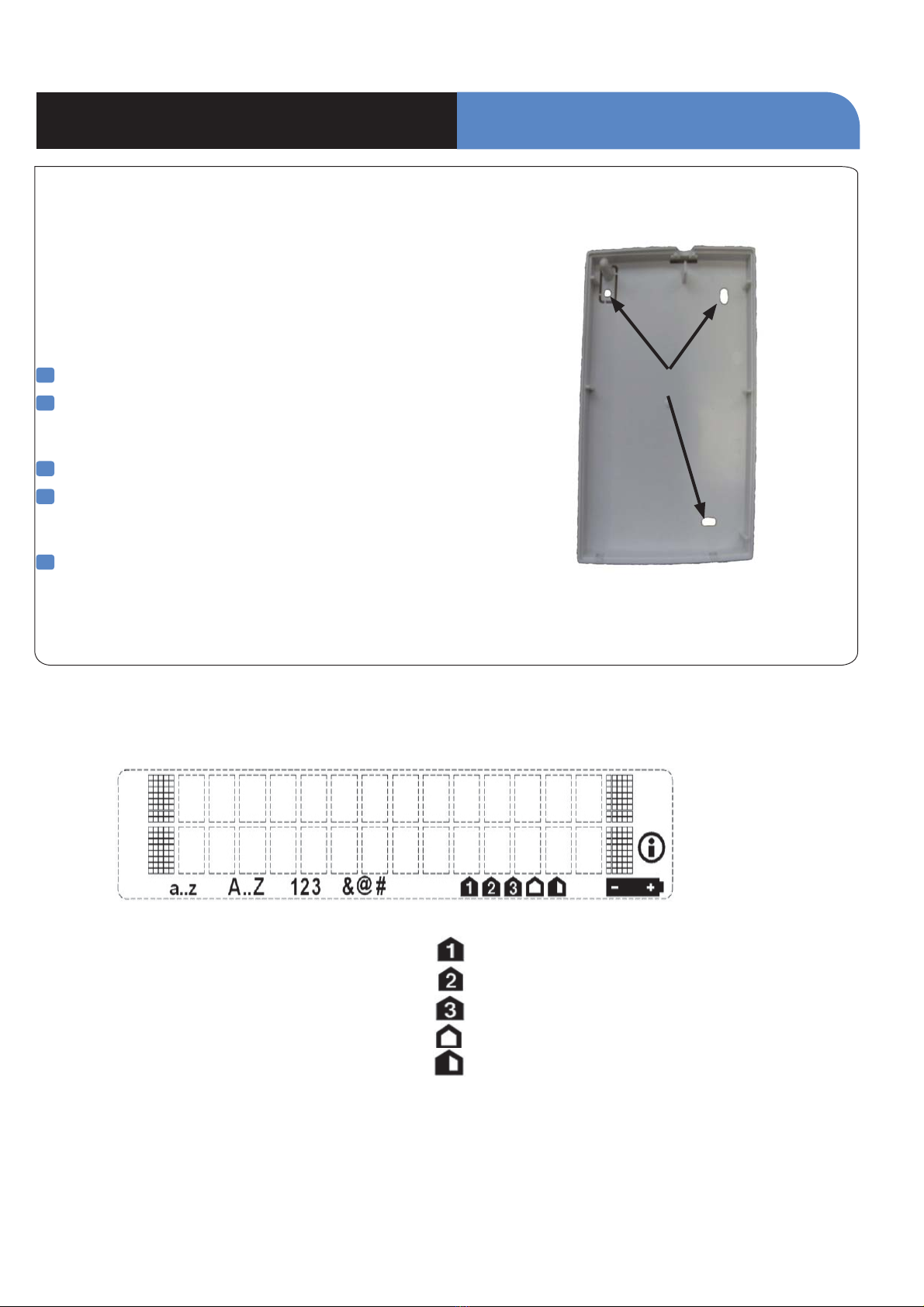
1Open the casing by turning the button toward the opened
padlock symbol and press down lightly on the button to
separate the cover.
2Insert 3 (minimum) or 4 (for longer life) SAFT 3.6v Lithium
AA LS14500 batteries.
3A New Installation: Put the control panel into
keypad registration mode by pressing the
programming button of the control panel one time.
OR
3B Adding to existing system: Using a programmed
alphanumeric keypad, proceed through menus until the
display shows ADD A NEW DEVICE. Press Yes. The
display shows PRESS PROGRAM BUTTON OF DEVICE.
OR
3C Adding to existing system without a keypad: Refer to
the installation manual of the control panel.
4Press and release the programming buttons (CLR and
ESC/NO) on the XMB keypad. The keypad LED will flash.
Wait for keypad display to show KEYPAD# RECORDED.
5 Press Yes. The display shows LANGUAGE: ENGLISH. Press
Yes. (This prompt will only appear when performing a
new installation).
6Display shows RADIO RANGE TEST? Press YES, the
keypad starts displaying the number of successful pings
to and from the control panel out of 9 (0/9 to 9/9).
Devices must be installed in a location with a stable 9/9 RF
test result to ensure reliable communication.
7Press YES to end radio range test, then press Esc/No.
Note: If this is a new installation (3A), the keypad display
prompts other system configuration data. If adding a keypad to
an existing (operational) system, proceed to step 8.
8When finished, exit from configuration mode.
Note: The control panel automatically assigns alphanumeric
keypads automatically to Area 1 (Entry/Exit delay)
*For complete details, refer to the control panel installation manual.
INSTALLATION DATA SHEET
Made by RSI VIDEO TECHNOLOGIES 1010-XMBIN February 2012
Keypad

1. Mounting
> Use proper tools and hardware.
> Mount indoor in a temperature-controlled environment.
> Mount keypad at height that provides proper viewing and
convenience for the customer.
> Mount in a location that provides customer convenience but
out of view from windows.
1Separate base from Keypad.
2Hold base against mounting surface and mark the three
mounting holes. Use the left or right side to level the
keypad.
3Drill pilot holes and install anchors where needed.
4Place base on mounting surface so holes line up with
pilot holes/anchors and secure base with appropriate
screws.
5Attach Keypad to base and secure by turning the button to
the closed padlock symbol.
Note: The XMB611 Keypad is a supervised device and must be
permanently mounted. This product is not intended
for portable use.
Mounting Holes
2. LCD Overview
Icons for entry mode:
a..z Lowercase
A..Z Uppercase
123 Keypad
&@# Symbols
Icons for arming mode:
Partition 1 or SP1 selected
Partition 2 or SP2 selected
Unused
External arming mode selected
Unused
Information Icon
Low Battery Icon
INSTALLATION DATA SHEET
Keypad

Keys Description
Panic
The panic request is launched in two steps:
1. 3 second press on the PANIC key
2. 1 second press on one of the three assistance keys
- The transmitted event type and siren activity depend on programming
OK Used to confirm any data capture or acknowledge messages
ESC Exits the current menu or cancels all data entered
CLR Deletes the last character entered
Symbols
The symbols: 1 . _ @ $ , ‘ ? ! ; : “ ( =space) are accessed through the 1
key
N`k_dlck`gc\(j\Zfe[gi\jj\jfek_\(b\p#k_\lj\i`jXYc\kfj\c\Zkk_\
symbol they are looking for.
9pgi\jj`e^Xe[_fc[`e^k_\(b\p#k_\c`e\n`k_XccjpdYfcjn`ccj_fn%Lj\
the arrow keys to select the symbol and press OK to confirm.
Special
Characters
Special Characters +0-*#=/%& ¥<>() are accessed through the 0 key
N`k_dlck`gc\(j\Zfe[gi\jj\jfek_\'b\pk_\lj\i`jXYc\kfj\c\Zkk_\
special character they are looking for.
9pgi\jj`e^Xe[_fc[`e^k_\(b\p#k_\c`e\n`k_XccjpdYfcjn`ccj_fn%Lj\
the arrow keys to select the symbol and press OK to confirm.
Capital Letter Press and hold appropriate letter key then repeat press
Auto-Repeat
mode
When a user holds an arrow key, the keypad will scroll all available values
Re-sync and
Enrollment
Press and release ESC/NO and CLR buttons simultaneously
3. Product Overview
LCD display
with automatic
backlight
RFID Badge reading zone
Arming
Keys
Red /
Green LED
4. Removal of Protective Film
They keypad is protected by a transparent film.
It is important to remove this film before using
the keypad.
5. RFID Tag Reading
The XMB keypad is equipped with a badge
reader ISO/IEC 14443A. The optimal reading
area is located around the 0 key. Compatible
with MiFare 13.56MHz 1K/4K badges.
The badge reader is inactive until approached
by a user. The system utilizes a capacitive
detector to energize the badge reader. It is
recommended the user holds the badge in place
in front of the reader rather than a quick swipe.
When a badge is detected the Green LED is lit
for a few seconds.
6. Keypad Use
7. Security
- Remove batteries before any maintenance
- WARNING, there is a risk of explosion if a
battery is replaced by an incorrect type!
- Observe polarity when inserting batteries
- Do not throw away used batteries they must
be properly disposed of according to
Hazardous material regulations for Lithium
batteries
Menu
Navigation
Assistance
Requests
INSTALLATION DATA SHEET
www.videofied.com.a
Keypad

8. Specifications
INSTALLATION DATA SHEET
Electrical Data
Panel Compatibility Videofied Alarm Panel XL,XT,XTIP, V6000
Power requirements:
Type: 3.6v SAFT Lithium, LS14500, AA Batteries Only
Nominal Voltage: 3.6v
Low Voltage Limit:
2.1v - LCD will stop functioning but communication is working
3.0v - LCD will function and communication is working
Quantity 3x or 4x
Battery life (estimated) Up to 4 years
RF technology:
2 way S2View© RSI Technologies
Radio type Spread Spectrum Bidirectional RF
Operating frequency
Transmission security AES algorithm encryption
Supervision Panel polls devices every 8 minutes
Antenna Integrated
Tamper detec tion Wall and cover tampered
Keypad:
Keys: 23x Keys
Allowed Time for Code Entry: 60s
Number of Illegal codes: 186 (depending on panel features)
User code input attempts before lockout: 5
Lockout duration: 90 seconds
Memory Lifetime: No Limit (Flash Memory)
Physical Data
Material ABS UL94-V0
Dimensions (LxWxD):6.3 x 3.6 x 1.2 Inches
(160 x 92 x 31 mm)
Weight 6.35oz (180gr) without batteries
Installation/Mounting
Wall Mount 3 Screws (including one for the tamper)
Case Lock Mechanical lock and optional screw
Assistance Request Police/Medical/Fire
Display type Liquid-crystal (LCD)
Display size Two lines, 16 characters each
Display backlighting Automatic
Badge Reader:
Format: ISO/IEC 14443A
Type: MiFare 13.56MHz 1K/4K
Built-in sounder:
Piezo Buzzer: Emits entry/exit delay beeps, alarms
Panic button One (Must be programmed/Enabled)
Operating temperature 14° - +104° F (-10° - +40° C)
Maximum relative humidity 75%, non-condensing
V
ideo Alarm Technologies Pty Ltd.
Enquiries: + 61 7 5491 7415 / 1300 46 44 55
www.videoalarmtechnologies.com.au
920Mh
920MHz frequency
hi
Keypad
Table of contents