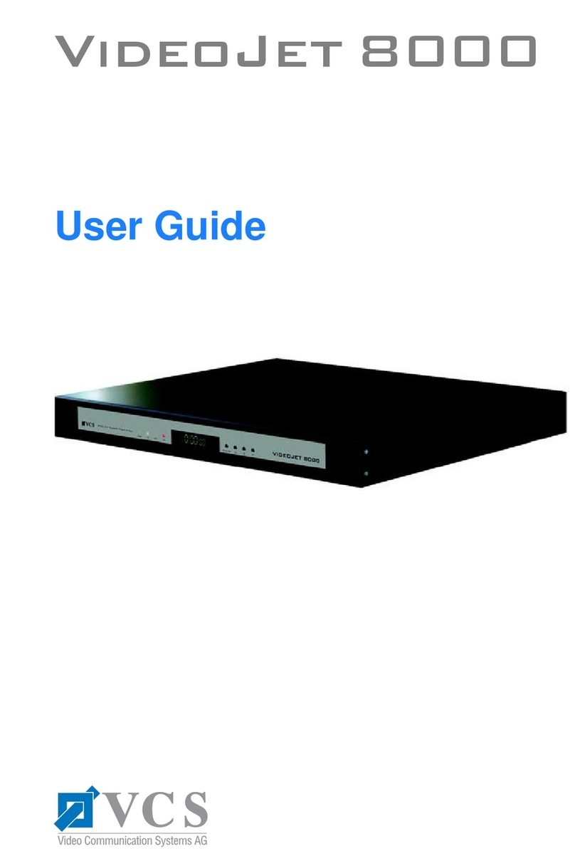
VCS VideoJet 1000 User manual

VideoJet 1000
Manual

Copyright This manual is the intellectual property of VCS and is protected by
copyright. All rights are reserved. No part of this document may be
reproduced or transmitted for any purpose, by whatever means, be
they electronic or mechanical, without the express written permis-
sion of VCS.
Edition: May 2003 (Version 2.5)
© Copyright 2003 VCS Video Communication Systems AG
Note This manual was compiled with the greatest of care and all informa-
tion double checked. At the time of printing the description was
complete and correct. Because of the further development of pro-
ducts, the content of the manual might change without prior notice.
VCS will not be liable for damage which is directly or indirectly due
to errors, incompleteness, or discrepancies between the manual
and the product described.
Trade marks All names used in this manual for hardware and software are very
probably registered trade marks and must be treated as such.

1
VideoJet 1000
Contents . . . . . . . . . . . . . . . . . . . . . . . . . . . . . . . . . . . . . . . . . . . 1
Chapter 1 Preface . . . . . . . . . . . . . . . . . . . . . . . . . . . . . . . . . . . . . . . . . . . . 5
Conventions . . . . . . . . . . . . . . . . . . . . . . . . . . . . . . . . . . . . . . . . 5
Intended use . . . . . . . . . . . . . . . . . . . . . . . . . . . . . . . . . . . . . . . . 6
EU Guidelines . . . . . . . . . . . . . . . . . . . . . . . . . . . . . . . . . . . . . . . 6
Rating plate . . . . . . . . . . . . . . . . . . . . . . . . . . . . . . . . . . . . . . . . . 7
Chapter 2 Safety Information . . . . . . . . . . . . . . . . . . . . . . . . . . . . . . . . . . . 9
Electrical shock hazard . . . . . . . . . . . . . . . . . . . . . . . . . . . . . . . . 9
Installation and operation . . . . . . . . . . . . . . . . . . . . . . . . . . . . . 10
Repairs and maintenance . . . . . . . . . . . . . . . . . . . . . . . . . . . . . 10
Chapter 3 Product Description . . . . . . . . . . . . . . . . . . . . . . . . . . . . . . . . 11
Supplied components . . . . . . . . . . . . . . . . . . . . . . . . . . . . . . . . 11
System requirements . . . . . . . . . . . . . . . . . . . . . . . . . . . . . . . . 11
Configuration requirements . . . . . . . . . . . . . . . . . . . . . . . . . . . . 11
Operational requirements . . . . . . . . . . . . . . . . . . . . . . . . . . . . . 12
Functional overview . . . . . . . . . . . . . . . . . . . . . . . . . . . . . . . . . 12
Rear panel connectors . . . . . . . . . . . . . . . . . . . . . . . . . . . . . . . 15
Front panel . . . . . . . . . . . . . . . . . . . . . . . . . . . . . . . . . . . . . . . . 16
Chapter 4 Installation . . . . . . . . . . . . . . . . . . . . . . . . . . . . . . . . . . . . . . . . 17
Rack mounting . . . . . . . . . . . . . . . . . . . . . . . . . . . . . . . . . . . . . 18
Connections . . . . . . . . . . . . . . . . . . . . . . . . . . . . . . . . . . . . . . . 21
Switching on/off . . . . . . . . . . . . . . . . . . . . . . . . . . . . . . . . . . . . . 25
Contents

Contents
2
VideoJet 1000
Setup using a terminal program . . . . . . . . . . . . . . . . . . . . . . . . 26
Chapter 5 Configuration with
Web Browser . . . . . . . . . . . . . . . . . . . . . . . . . . . . . . . . . . . . . . 29
Establishing the connection . . . . . . . . . . . . . . . . . . . . . . . . . . . . 29
Selecting the configuration mode . . . . . . . . . . . . . . . . . . . . . . . 30
Installation wizard . . . . . . . . . . . . . . . . . . . . . . . . . . . . . . . . . . . 32
System Overview . . . . . . . . . . . . . . . . . . . . . . . . . . . . . . . . . . . 35
Expert Mode . . . . . . . . . . . . . . . . . . . . . . . . . . . . . . . . . . . . . . . 74
Function test . . . . . . . . . . . . . . . . . . . . . . . . . . . . . . . . . . . . . . 119
Chapter 6 Operation . . . . . . . . . . . . . . . . . . . . . . . . . . . . . . . . . . . . . . . . 121
Operation with
MS Internet Explorer . . . . . . . . . . . . . . . . . . . . . . . . . . . . . . . . 121
Storing snapshots . . . . . . . . . . . . . . . . . . . . . . . . . . . . . . . . . . 125
Storing MPEG sequences . . . . . . . . . . . . . . . . . . . . . . . . . . . . 126
Harddisk activity . . . . . . . . . . . . . . . . . . . . . . . . . . . . . . . . . . . 126
Playback of recorded sequences . . . . . . . . . . . . . . . . . . . . . . 127
Back-up . . . . . . . . . . . . . . . . . . . . . . . . . . . . . . . . . . . . . . . . . . 130
Hardware connections
between VideoJet Units . . . . . . . . . . . . . . . . . . . . . . . . . . . . . . 131
Operation with Software-Decoder . . . . . . . . . . . . . . . . . . . . . . 132
Chapter 7 Maintenance . . . . . . . . . . . . . . . . . . . . . . . . . . . . . . . . . . . . . . 133
Network check . . . . . . . . . . . . . . . . . . . . . . . . . . . . . . . . . . . . . 133
Repair . . . . . . . . . . . . . . . . . . . . . . . . . . . . . . . . . . . . . . . . . . . 133
Passing on, Disposal . . . . . . . . . . . . . . . . . . . . . . . . . . . . . . . . 134
Chapter 8 Appendix . . . . . . . . . . . . . . . . . . . . . . . . . . . . . . . . . . . . . . . . 135
Faults – possible causes and remedy . . . . . . . . . . . . . . . . . . . 135
LEDs . . . . . . . . . . . . . . . . . . . . . . . . . . . . . . . . . . . . . . . . . . . . 137
Glossary . . . . . . . . . . . . . . . . . . . . . . . . . . . . . . . . . . . . . . . . . 138
Specifications . . . . . . . . . . . . . . . . . . . . . . . . . . . . . . . . . . . . . 141

Contents
3
VideoJet 1000
Chapter 9 Index . . . . . . . . . . . . . . . . . . . . . . . . . . . . . . . . . . . . . . . . . . . . 143

Contents
4
VideoJet 1000

5
VideoJet 1000
Preface
1
These installation and operating instructions are intended for per-
sons authorised to install and operate the VideoJet 1000. Interna-
tional, national and any relevant regional regulations relating to
electronics must be observed at all times. The operating instruc-
tions explain the installation and operation of the VideoJet 1000.
Conventions
In this manual, the following symbols and notations are used to
draw attention to special situations:
Warning! or Attention!
This symbol indicates that failure to follow the safety instructions
given may directly endanger people, cause damage to the system
or to other equipment. The symbol represents a direct threat of dan-
ger.
Note
This symbol indicates tips and notes that make using the device
easier and more convenient.
Note
This symbol indicates that you might have to find out special infor-
mation to be able to make the settings or start up the system cor-
rectly.

Preface
6
VideoJet 1000
The following typographic conventions are used in this manual:
Intended use
The Network Video Server VideoJet 1000 serves to transmit video,
audio and control signals via data networks (Ethernet LAN, Inter-
net). Due to the integrated hard disk the device provides DVR func-
tionality. It is designed for use in CCTV systems. The connection of
an external alarm generator allows various functions to be triggered
automatically. Other applications are not permitted.
In the event of questions concerning the use of the server which are
not answered in this manual, please contact:
VCS Video Communication Systems AG
Forchheimer Strasse 4
90425 Nuremberg/Germany
Phone +49 (0) 911 9 34 56-0
Fax +49 (0) 911 9 34 56-66
EU Guidelines
The Network Video Server VideoJet 1000 complies with the speci-
fications of European Guidelines 89/336 (Electromagnetic Compat-
ibility) and 73/23, amended by 93/68 (Low-Voltage Guideline).
Configuration Window and menu names, parameters and
buttons
[Enter], [C] Key names
[Ctrl] + [C] Two or more keys that are pressed simul-
taneously.
ping Command line input and output

Preface
7
VideoJet 1000
Rating plate
For exact identification, you will find the model designation and
serial number on the rating plate on the bottom of the housing.
Please note this information here before installation in order to have
it to hand in the event of queries or spare parts orders.

Preface
8
VideoJet 1000

9
VideoJet 1000
Safety Information
2
Electrical shock hazard
!Never attempt to connect the unit to any power network other
than the one for which it was intended.
!Do not open the housing of the unit.
!Disconnect the unit from the mains power supply and from all
other devices if a fault occurs.
!Install the unit only in a dry place protected against the elements.
!If you are uncertain about the safe operation of the unit, shut it
down immediately and secure it to prevent any unauthorised
start-up. Safe operation is no longer possible, for example,
– if damage is visible to the unit or the cables,
– if the unit no longer operates correctly,
– if the server has been exposed to rain or moisture,
– if objects have penetrated inside the unit,
– after long storage under improper conditions or
– after heavy demands during transport.
Have the system checked by VCS in such cases.

Safety Information
10
VideoJet 1000
Installation and operation
!All applicable electrical codes and regulations must be observed
and followed at all times during the installation.
!Before installing or operating the system, ensure that you have
read and understood the documentation for other equipment
connected to the unit, e.g. cameras. These contain important
safety notices and information concerning permissible applica-
tions.
!Perform only the installation and operating work described in this
manual. All other work beyond this may lead to injuries to per-
sons and damage to the system or other equipment.
Repairs and maintenance
!Never open the housing of the VideoJet 1000. The unit contains
no parts which you can repair or replace.
!Ensure that only qualified, specialist personnel (electrical techni-
cians) are permitted to carry out maintenance or repair work.

11
VideoJet 1000
Product Description
3
Supplied components
!Network Video Server VideoJet 1000 incl. mains cable
!RS232 Null modem cable
!Brief description “First Steps” German/English
!German/English handbook on CD-ROM
!VCS software on CD-ROM
!3.5’’ hard drive
System requirements
!Computer with Windows 98/2000/XP operating system and
access to network and
!Web browser Microsoft Internet Explorer (version 5 or higher) or
free serial interface port and terminal program
Configuration requirements
!Computer with Windows 98/2000/XP operating system and
access to network and
!Web browser Microsoft Internet Explorer (version 5 or higher) or
decoder software, e.g. VIDOS from VCS

Product Description
12
VideoJet 1000
Operational requirements
!Computer with Windows 98/2000/XP operating system and
access to network and
!Web browser Microsoft Internet Explorer (Version 5 or higher) or
decoder software, e.g. VIDOS from VCS
or
!VideoJet 1000 acting as receiver and video monitor
Functional overview
Network
video server
The VideoJet 1000 is a network video server. Its primary function is
to decode and encode video, audio and control data for transmis-
sion over an IP network. Because it uses existing networks, rapid
and simple integration into CCTV installations via local networks
can be achieved.
The VideoJet 1000 is designed either as a desktop unit or for buil-
ding into equipment cabinets. Using the appropriate mounting
frame, installation of a single unit or two units alongside each other
on a 19“ shelf is possible.
Two units, i.e. a VideoJet 1000 as transmitter and a VideoJet 1000
as receiver, can form a stand alone system for data transfer without
a PC. The system can be extended to include additional transmit-
ters and receivers so that video images from one transmitter can be
simultaneously received on a number of receivers.
Receiver The appropriate VideoJet 1000 or a computer with installed deco-
ding software, e.g. VIDOS from VCS or with the installed web brow-
ser Microsoft Internet Explorer, can be used as a receiver.
DVR Due to the integrated hard disk the VideoJet 1000 can also function
as a digital video recorder allowing for local long-time recording.

Product Description
13
VideoJet 1000
Video encoding/
Multicast
The VideoJet 1000 operates with the video compression standards
MPEG-2 and MPEG-4. Thanks to efficient MPEG-2 encoding, the
data bit rate remains low even with high image quality and, in addi-
tion, can be matched into the local environment within wide limits.
In this process, simultaneous encoding of the video signal accor-
ding to MPEG-4 is supported, so that concurrent transmission using
low bandwidth, e.g for Internet streaming, is possible.
In suitably configured networks, simultaneous transmission in real
time to a number of receivers is possible using the Multicast func-
tion. A requirement here is the implementation of the UDP and
IGMP protocols on the network.
Remote control For the remote control of external equipment, e.g. remote pan and
tilt heads or motorized zoom lenses, the control data are transmit-
ted via the bidirectional serial interface of the VideoJet 1000. This
interface is also available for the transmission of transparent data.
Configuration Configuration of the VideoJet 1000 can be carried out using a brow-
ser via the local network (Intranet) or from the Internet.
Similarly, firmware updates and rapid loading of equipment configu-
rations are also possible.
Snapshots Individual video frames (snapshots) can be called up in JPEG for-
mat by the VideoJet 1000, stored on the computer hard drive or can
be displayed in a separate browser window.
Back-up Can be accomplished from either the livepage or directly from the
HDD-Replay mode through a simple mouse click.

Product Description
14
VideoJet 1000
Summary The main functions of the VideoJet 1000 can be summarized as
follows:
!Video, audio and data transmission via IP data nets
!Multicast function for simultaneous transmission to a number of
receivers
!Analog BNC composite video input (PAL/NTSC)
!Analog BNC composite video output (PAL/NTSC)
!Audio input and output (Stereo)
!Video and audio encoding to the international standards
MPEG- 4, MPEG-2 and MPEG-1
!Integrated Ethernet interface (10/100 Base-T)
!Two transparent bidirectional data channels via serial interface
ports RS232/RS422/RS485 and RS232
!Local long-term recording on integrated 3,5“ hard disk
!Remote control of all internal functions via TCP/IP
!Password protection to prevent unauthorized connection or
alterations to configuration
!Closed contact input for external sensor (e.g. door contact)
!Closed contact output for external equipment (e.g. lights or
acoustic alarms)
!Event driven automatic connection setup (e.g. on switch-on and
with alarms)
!Integrated video sensor for motion alarms
!Video signal monitoring
!Rapid and user friendly configuration via web browser
!Firmware update through flash memory

Product Description
15
VideoJet 1000
Rear panel connectors
1Video input Video In
BNC socket for video source
2Video output Video Out
BNC socket for an analog video monitor
3Audio connectors Audio Out and Audio In
3.5 mm stereo jack sockets for connection of a loudspeaker and
microphone
4Screw connectors Output and Input
for external sensors or switches and
for switching external equipment (e.g. lights or acoustic alarms)
5Serial interface port COM1: RS232/485
9-pin sub-D socket (m) for control data transmissions
(protocols RS232, RS422 and RS485) and for configuration
using terminal software
6Serial interface port COM2: RS232
9-pin sub-D socket (m) for control data transmissions
(protocol RS232) and for configuration using terminal software
7RJ45 Ethernet connector
for connecting to the network
8Socket Power
mains cable connector

Product Description
16
VideoJet 1000
Front panel
9Diode IR
Infrared receiver (for future development)
10 LED HDD
flashes red during data transmissions to/from the hard drive
11 LED VIDEO
lights up green if a video signal is present on the input
12 LED IN
lights up red to indicate active alarm, green to indicate alarm
ready
13 LED OUT
lights up green to indicate switched relay
14 LED COM
flashes yellow during active data transmissions on the serial
interface ports
15 LEDs ETHERNET
green LED lights up with physical network connection
red LED flashes when data packets are being transmitted
16 LED POWER
lights up green to indicate operationally ready
Additional information on the LEDs can be found on page 137.

17
VideoJet 1000
Installation
4
Due to its compact design and small footprint, the VideoJet 1000
can be used as a desk top unit occupying minimum space.
Using the mounting shelf unit, Accessory Kit 19“ Rack, it is also
possible to mount the unit into a standard 19“ equipment cabinet.
The following installation requirements must be satisfied:
!Do not mount the equipment in close proximity to heaters or
other sources of heat. Avoid locations subject to direct sunlight.
!Allow sufficient space for laying of cables.
!Ensure adequate ventilation of the equipment. When installing in
equipment cabinets with other equipment, make allowances for
the total heat load.
!Only use the cables supplied when connecting up the equipment
or, if necessary, use cables suitably screened for interference.
!Position and lay all cables where they will not be subject to dam-
age and ensure strain relief is provided where necessary.
Warning!
The unit is intended for internal use. Select a suitable location for
installation where the equipment is not subjected to either extreme
temperatures nor to extreme humidity. The ambient temperature
must be between 0 and +50 °C, the relative humidity may not
exceed 80% (non-condensing).
The equipment becomes warm in normal operation. Ensure that
ventilation is adequate and also that there is sufficient clearance
between it and heat sensitive objects or equipment.

Installation
18
VideoJet 1000
Rack mounting
The VideoJet 1000 is adapted for installation into a standard
19“ equipment rack. Either a single unit or two units secured
together alongside each other can be mounted on a single shelf.
For rapid and secure installation, use the appropriate mounting set
from VCS:
!Accessory Kit 19“ Rack order no. 1412,
Mounting set for one or two units
Warning!
In the case of rack mounting ensure adequate ventilation for all
units: free space around the equipment must be at least 5 cm left
and right and must be at least 10 cm to the rear.
The ambient temperature must be between 0 and +50°C, the
relative humidity may not exceed 80%.
The equipment generates heat during normal operation. Make sure
there is sufficient clearance where necessary to heat sensitive
objects or equipment.
When installing additional equipment, direct contact with the
VideoJet 1000 is only permitted if the surface temperature of the
neighboring equipment does not exceed +50 °C.
Other manuals for VideoJet 1000
1
Table of contents
Other VCS Network Hardware manuals
Popular Network Hardware manuals by other brands

Korenix
Korenix JetNet 2205 Quick installation guide

SkyPilot
SkyPilot SkyConnector Outdoor installation guide

CoreTigo
CoreTigo TigoBridge B1 user manual

Vision
Vision TECHCONNECT TC2-MATRIXBRIDGE owner's manual

Western Digital
Western Digital My Cloud EX2 Ultra user manual

Metrodata
Metrodata PacketLINK user manual