vds PM400 Technical document

ATTENZIONE!! Prima di effettuare l'installazione, leggere attentamente questo
manuale che è parte integrante di questa confezione.
Il marchio CE è conforme alla direttiva europea
CEE 89/336 + 92/31 + 93/68 D.L. 04/12/1992 N. 476.
I nostri prodotti se installati da personale specializzato idoneo alla
valutazione dei rischi, rispondono alle normative UNI EN 12453-EN 12445
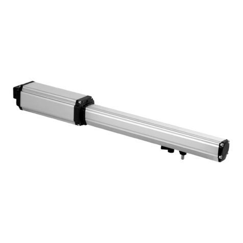
PM/PM1
ATTUATORE
PER CANCELLI E PORTE AD
ANTE BATTENTI

Composizione dell’imballo .................................................................. 2
Prospetto generale ............................................................................. 3
Dati tecnici .......................................................................................... 3
Dimensioni ..........................................................................................
4
Collegamento tipo e sezione cavi ...................................................... 4
Considerazione per l’installazione ......................................................
5
Modalità’ di installazione .....................................................................
5-6
Inconvenienti : cause e soluzioni....................................................... 7
Suggerimenti e sicurezza ................................................................... 8
CONTENUTO DELL’IMBALLO
1- ATTUATORE
1- KIT STAFFE DI FISSAGGIO
1- COPPIA DI CHIAVI SBLOCCO
1- CONDENSATORE (per versioni 230Vca)

DATI TECNICI
Peso Max anta 250 Kg
Lunghezza Max anta 1,80 (300) - 2,50 (400) - 3,50 (600) mt
Alimentazione motore 12Vdc 230 Vac
Potenza motore 50 W 250 W
Giri motore 900 800
Condensatore / 12,5 µF
Sblocco meccanico per manovra di emergenza / / Con chiave
Temperatura di funzionamento -20° C / +55° C
Peso 7.5 Kg
Grado di protezione IP 55
Tempo di apertura 90° 15/25/30 sec
Corsa stelo
300/400
300/400/600
Forza di spinta 1500 N
Assorbimento medio motore 3 A 1 A
2
5
1- Attuatori
2- Fotocellula esterna
3- Lampeggiatore
4- Antenna
Esempio di installazione
43
1
1
5
5- Fotocellula interna
6- Quadro di comando
7- Selettore a chiave
8- Radiocomando
6
7
8
PM1
(irreversibile)
PM
(reversibile)

DIMENSIONI
COLLEGAMENTO TIPO E SEZIONE CAVI
2X1,5mm2 (12 Vdc )
4X1,5mm2 (230 Vca )
2X0,75mm2
4X0,75mm2
4X0,75mm2
RX fotocellula TX fotocellula
2X0,75mm2
3X1,5mm2
Linea 230V
95 mm
280 mm
330 mm
375/475/675 mm 300/400/600 mm
95 mm

MODALITA’ D’INSTALLAZIONE
CONSIDERAZIONI PER L’INSTALLAZIONE
·Le operazioni di installazione e collaudo devono essere eseguite solo da personale
qualificato ai fini di garantire la corretta e sicura funzionalità del cancello automatico.
·La casa costruttrice, declina ogni responsabilità per i danni derivati da eventuali errate
installazioni dovute ad incapacità e/o negligenza.
·Prima di procedere al montaggio dell’automatismo, si verifichi che il cancello sia
perfettamente funzionante, ben incardinato alle proprie cerniere e opportunamente lubrificato
nonché rispondente alle normative sulla sicurezza vigente nel Paese dove viene effettuata
l’installazione.
1- Prima di procedere al fissaggio delle staffe in dotazione, determinare le quote utilizzando i
dati riportati nella Tabella 1, tenendo conto che sono validi se l’attuatore è in posizione di
massima estensione meno un centimetro della corsa disponibile (CD) quando il cancello è
chiuso per ottenere la massima efficienza di funzionamento.
2- I dati B in tabella, con riferimento ai singoli valori di A, sono da considerarsi come valori
(consigliati)
3- Per l’ancoraggio del pistone utilizzare le staffe di fissaggio in dotazione.
QUOTE E TABELLA
TABELLA 1
GRADI
A
B
Cu
90
80
80
160
90
90
180
100
100
200
100
150
250
100
110
110
220
120
120
240
120
100
220
110
130
130
260
140
140
280
150
150
300
90° con corsa diponibile 400mm
160
160
320
175
175
350
190
190
380
200
200
400
90° corsa 600 mm
300
300
600
Nota1: A+B = CU(Corsa utilizzata ) CD= (Corsa disponibile) = 300 mm /400 mm /600mm
1- Stabilire la quota A + B che si
desidera utilizzare.
2- Nota 1: La corsa utilizzabile CU
dell’attuatore non dovrà mai essere
uguale o superiore alla corsa
disponibile CD
3- Nota 2: La somma delle quote A + B,
determina la corsa
utilizzata CU .

Aprire il tappo posto sotto sulla
parte inferiore dell’attuatore,
inserire la chiave in dotazione
e ruotare in senso orario
Procedura di sblocco
INSTALLAZIONE PIASTRE DI FISSAGGIO
Fissare la piastra posteriore al
pilastro.(FIG. 1)
Ancorare la parte posteriore
dell’attuatore alla piastra e
fissarla saldamente. ( FIG. 2)
(FIG. 2)
Attenzione! Nel determinare l’altezza da terra a cui fissare la piastra sul pilastro(FIG.1), tenere
conto che la piastra per l’ancoraggio del pistone sul cancello deve essere fissata allo stesso livello.
(FIG.3)
Installazione della piastra ancoraggio pistone al cancello
1- Fissare la piastra anteriore di ancoraggio
sull’attuatore. (FIG.4)
2- Chiudere il cancello.
3- Accostare al cancello l’attuatore con la
piastra già fissata.
4- Portare l’attacco a fine corsa, riportarlo
indietro di circa 1cm e segnare la
posizione della piastra.
5- Effettuare la stessa operazione in apertura
6- Se le posizioni corrispondono fissare
saldamente la piastra sul cancello. In caso
contrario rivedere le quote Ae B della
tabella 1
(FIG. 3)
(FIG. 1)
(FIG. 4)

INCONVENIENTI-CAUSE E SOLUZIONI
INCONVENIENTE CAUSA PROBABILE SOLUZIONE
Ad un comando con
il radiocomando o con
il selettore a chiave,
il cancello non si apre o
il motore non parte
Alimentazione di rete
230 volt assente
Controllare l’interrutore
principale
Presenza di STOP di
emergenza
Controllare eventuali
selettori o comandi di
STOP. Se non utilizzati
verificare ponticello su
ingresso contatto STOP
su centralina
Fusibile bruciato Sostituirlo con uno dello
stesso valore.
Cavo di alimentazione del
o dei motori non collegato
o difettoso.
Collegare il cavo
nell’apposito morsetto o
sostituirlo.
C’è un ostacolo in mezzo
alla fotocellula o non
funziona
Verificare il collegamento,
togliere eventuale ostacolo.
Ad un comando con il
radiocomando non apre,
ma funziona con il
comando a chiave
Il radiocomando non e
stato memorizzato o la
batteria è scarica
Eseguire la procedura di
riconoscimento del
radiocomando sul
ricevitore radio o sostituire
la batteria con una nuova .
Il cancello parte, ma si
ferma
La forza del o dei motori è
insufficiente
Modificare il valore con il
trimmer FORZA posto
sulla centrale
Un anta si apre e una si
chiude
Il collegamento non è
corretto
Scambiare la polarità dei
cavi del motore
interessato
N:B. - Se l’inconveniente permane, contattare il proprio Rivenditore o il più vicino Centro
Assistenza

AVVERTENZE PER LA SICUREZZA
Le presenti avvertenze sono parti integranti ed essenziali del prodotto e devono essere
consegnate all’utilizzatore. Leggerle attentamente in quanto forniscono importanti indicazioni
riguardanti l’installazione, l’uso e la manutenzione. E’ necessario conservare il presente modulo e
trasmetterlo ad eventuali subentranti nell’uso dell’impianto. L’errata installazione o l’utilizzo
improprio del prodotto può essere fonte di grave pericolo.
ISTRUZIONI PER L’INSTALLAZIONE
·L’installazione deve essere eseguita da personale professionalmente competente e
inosservanza della legislazione locale, statale, nazionale ed europee vigente.
·
·Prima di iniziare l’installazione verificare l’integrità del prodotto
·
·La posa in opera, i collegamenti elettrici e le regolazioni devono essere effettuati a
“Regola d’arte”.
·I materiali d’imballaggio (cartone, plastica, polistirolo, ecc.) non vanno dispersi nell’ambiente
e non devono essere lasciati alla portata dei bambini in quanto potenziali fonti di pericolo.
·
·Non installare il prodotto in ambienti a pericolo di esplosione o disturbati da campi
elettromagnetici. La presenza di gas o fumi infiammabili costituisce un grave pericolo per la
sicurezza.
·
·Prevedere sulla rete di alimentazione una protezione per extratensioni, un
interruttore/sezionatore e/o differenziale adeguati al prodotto e in conformità alle normative
vigenti.
·
·Il costruttore declina ogni e qualsiasi responsabilità qualora vengano installati dei dispositivi
e/o componenti incompatibili ai fini dell’integrità del prodotto, della sicurezza e del
funzionamento.
·
·Per la riparazione o sostituzione delle parti dovranno essere utilizzati esclusivamente ricambi
originali.
·
·L’installatore deve fornire tutte le informazioni relative al funzionamento, alla manutenzione e
all’utilizzo delle singole parti componenti e del sistema nella sua globalità.
AVVERTENZE PER L’UTENTE
·Leggere attentamente le istruzioni e la documentazione allegata.
·Il prodotto dovrà essere destinato all’uso per il quale è stato espressamente concepito. Ogni
altro utilizzo è da considerarsi improprio e quindi pericoloso. Inoltre, le informazioni contenute
nel presente documento e nella documentazione allegata, potranno essere oggetto di
modifiche senza alcun preavviso. Sono infatti fornite a titolo indicativo per l’applicazione del
prodotto. La casa costruttrice declina ogni ed eventuale responsabilità.
·Tenere i prodotti, i dispositivi, la documentazione e quant’altro fuori dalla portata dei bambini.
·In caso di manutenzione, pulizia, guasto o cattivo funzionamento del prodotto, togliere
l’alimentazione, astenendosi da qualsiasi tentativo d’intervento. Rivolgersi solo al personale
professionalmente competente e preposto allo scopo. Il mancato rispetto di quanto sopra può
causare situazioni di grave pericolo.
I dati e le immagini sono puramente indicativi
VDS si riserva il diritto di modificare in qualsiasi momento le caratteristiche dei prodotti
descritti a suo insindacabile giudizio, senza alcun preavviso.
Rev. 1-07/13 IT
Via Circolare p.i.p. N° 10
65010 Santa Teresa di Spoltore (PE) - ITALY
Tel. +39 085 4971946 - FAX +39 085 4973849

WARNING!! Before installing, thoroughly read this manual that is an integral
part of the pack
The CE mark conforms to European directive
EEC 89/336 + 92/31 + 93/68 D.L. 04/12/1992 N. 476.
Our products if installed by qualified personnel capable to evaluate risks,
comply with norms UNI EN 12453, EN 12445
PM/PM1
OPERATOR
FOR SWING GATES
AND DOORS

PACKING CONTENTS ............................................................................. 2
VIEW OF TYPICAL AUTOMATION AND NAMES OF COMPONENTS .............
3
TECHNICAL DATA....................................................................................
3
DIMENSIONS ......................................................................................... 4
TYPICAL CONNECTION AND CABLE SECTION.......................................... 4
CONSIDERATIONS FOR INSTALLATION................................................... 5
INSTALLATION....................................................................................... 5-6
TROUBLESHOOTING............................................................................... 7
SAFETY PRECAUTIONS ..........................................................................
8
PACKING CONTENTS
1- OPERATOR
1- KIT FASTENING PLATES AND
RELATIVE ACCESSORIES
1- UNLOCKING KEY
1- CONDENSER (230Vca)

TECHNICAL DATA
Max. weight of gate 250 Kg
Max. width of gate 1,80 (300) - 2,50 (400) - 3,50 (600) mt
Motors power supply 12Vdc 230 Vac
Motor power 50 W 250 W
Motor RPM 900 800
Condenser / 12,5 µF
Mechanical unlock for emergency manoeuvre / / With key
Working temperature -20° C / +55° C
weight 7.5 Kg
Protection rating IP 55
Opening time 90° 15/25/30 sec
Rod stroke
300/400
300/400/600
Force of thrust 1500 N
motor current input 3 A 1 A
2
5
VIEW OF TYPICAL AUTOMATION AND NAMES OF COMPONENTS
1- Operator
2- External photocell
3- Flashing warning light
4- Antenna
Optimal installation
43
1
1
5
5- Internal photocell
6- Electronic control unit
7- Key-switch
8- Remote control
6
7
8
PM1
(not reversible)
PM
(reversible)

DIMENSIONS
TYPICAL CONNECTION AND CABLE SECTION
2X1,5mm2 (12 Vdc )
4X1,5mm2 (230 Vca )
2X0,75mm2
4X0,75mm2
4X0,75mm2
RX Photocell TX Photocell
2X0,75mm2
3X1,5mm2
230V Line
95 mm
280 mm
330 mm
375/475/675 mm 300/400/600 mm
95 mm

INSTALLATION
CONSIDERATIONS FOR INSTALLATION
1- Before fastening the brackets provided, establish the coordinates using the data given in
Table 1,
bearing in mind that they are valid if the operator is at maximum extension minus one
centimetre of the available stroke (CD) when the gate is closed to obtain maximum working
efficiency.
2- Data B in the table, with reference to the single values A, are to be considered as values
(recommended).
3- To anchor the piston, use the fastening brackets provided.
COORDINATES AND TABLE
TABLE 1
Opening angle A B Cu
90
80
80
160
90
90
180
100
100
200
100
150
250
100
110
110
220
120
120
240
120
100
220
110
130
130
260
140
140
280
150
150
300
90° Available stroke = 400mm
160
160
320
175
175
350
190
190
380
200
200
400
90° stroke 600 mm
300 300 600
Note1: A+B = CU(Stroke used) CD= (Available stroke) = 300 mm /400 mm /600mm
·The installation and testing operations must be performed solely by qualified personnel in
order to guarantee the proper and safe operation of the automatic gate.
·The company declines any responsibility for damage caused by incorrect installations due
to incompetence and/or negligence.
·Before assembling the automatism, check that the gate is in perfect working order, hangs
well on its hinges and is suitably lubricated. It must also comply with the safety standards
in force in the country of installation..
1. Establish coordinates A + B that are
to be used.
2. Note: The stroke used (CU) of the
operator must never be equal or
greater than the available stroke (CD)
3. The sum of coordinates A + B,
establishes the stroke used CU .

INSTALLATION OF FASTENING PLATES
Fasten the plate provided to the
post (fig. 1)
Anchor the rear part of the piston to
the plate and fasten it firmly (fig. 2).
Warning! When establishing the height off the ground at which to fasten the plate to the post
(fig. 1), keep in mind that the plate for anchoring the piston to the gate must be fastened at the
same level (fig. 3)
Installing the anchor plate on the piston to the gate
Release procedure
Open the plug located
underneath on the lower
part of the piston, insert
the key provided and turn
clockwise
(FIG. 2)
(FIG. 3)
(FIG. 1)
(FIG. 4)
1. Fit the anchor plate onto the piston (fig. 4)
2. Close the gate
3. Move the piston with the plate already
fitted towards the gate
4. Move the fitting to limit stop, then move it
back by approximately 1 cm and mark the
position of the plate.
5. realize the same operation in opening.
6. If positions correspond, fix the plate on the
gate; otherwise revise Aand Bunits
(table 1)

TROUBLESHOOTING
PROBLEM PROBABLE CAUSE SOLUTION
On giving a command with
the remote
control or with the
key-switch, the gate
doesn’t open or the motor
doesn’t start
230 volt mains voltage
absent Check master switch
Emergency STOP present
Check for any STOP
selectors or commands.
If not used, check jumper
on STOP contact input on
the control board
Fuse blown Replace with one of same
value.
Power cable of motor or
motors not
connected or faulty.
Connect the cable to
appropriate
terminal or replace.
The photocell is not
functioning or the
beam is interrupted
Check the connection,
remove any
obstacle across the beam
On giving a command with
the remote control, the
gate doesn’t open but
works with the key
command
The remote control has not
been
memorised or the battery
is flat
Carry out the remote
control learning
procedure on the radio
receiver or replace the
battery with a new one..
The gate starts, but stops
immediately
The force of the motor or
motors is insufficient
Modify the value with the
FORCE trimmer on the
control unit
One wing opens and the
other closes
The connection is not
correct
Invert the connection of
the cable of the motor
which rotates in the wrong
sense
N.B. - If the problem persists, contact your Retailer or the nearest Service
Centre

SAFETY PRECAUTIONS
These warnings are an essential, integral part of the product and must be given to the user. They
provide important indications on the installation, use and maintenance and must be read carefully.
This form must be preserved and passed on to subsequent users of the system. The incorrect
installation or improper use of the product may be dangerous.
INSTALLATION INSTRUCTIONS
• The installation must be performed by professionally skilled personnel and in compliance with
current local, state, national and European legislation.
• Before beginning the installation, check the integrity of the product.
• The laying of cables, electrical connections and adjustments must be workmanlike performed.
• The packing materials (cardboard, plastic, polystyrene, etc.) are a potential hazard and should
be disposed of correctly and not left within reach of children.
• Do not install the product in potentially explosive environments or environments disturbed by
electromagnetic fields. The presence of inflammable gases or fumes is a grave danger to
safety.
• Set up a safety device for overvoltage, a disconnecting and/or differential switch suitable for
the product and conforming to current standards.
• The manufacturer declines any and all responsibility for product integrity, safety and operation
in the event incompatible devices and/or components are installed.
• Solely original spare parts should be used for repairs and replacements.
• The installer must provide all the information relating to the operation, maintenance and use of
the individual parts, components and system as a whole.
WARNINGS FOR THE USER
• Read the instructions and enclosed documentation carefully.
• The product must be used for the express purpose for which it was designed. Any other use is
considered improper and therefore hazardous. In addition, the information given in this
document and in the enclosed documentation may be subject to modifications without prior
notice. It is given as an indication only for product application. The company declines any
responsibility for the above.
• Keep products, devices, documentation and anything else provided out of reach of children.
In the event of maintenance, cleaning, breakdown or faulty operation of the product, cut off the
power and do not attempt to operate on the product. Contact solely the professionally skilled
personnel responsible for these operations. Failure to adhere to the above indications may be
dangerous.
Rev. 1-07/13 ING
The data and images are for guidance only
VDS reserves the right to change at any time characteristics of the products described in
its sole discretion, without notice.
Via Circolare p.i.p. N° 10
65010 Santa Teresa di Spoltore (PE) - ITALY
Tel. +39 085 4971946 - FAX +39 085 4973849

ACTUADORES PARA PUERTAS
DE HOJAS BATIENTES
Atención! Antes de efectuar la instalación, leer atentamente el presente
manual, que es parte integrante de este producto.
La marca CE es conforme con la directiva europea R&TTE 99/05CE
Nuestros productos si son instalados por personal cualificado capaz de la
evaluaccion de riesgos, cumplen con la norma UNI EN 12453, EN 12445
PM/PM1

Composición embalaje ........................................................................
2
Prospecto general ...............................................................................
3
Datos Técnicos.....................................................................................
3
Dimensión ............................................................................................
4
Conexiones y secciones de cables ....................................................
4
Consideraciones para la instalación ....................................................
5
Modalidad de instalación .....................................................................
5-6
Inconvenientes : causas y soluciones................................................ 7
Sugerencias y seguridad .....................................................................
8
CONTENIDO EMBALAJE
1- Actuador
1- Kit placas de fijación y accesorios
1- Par de llaves de desbloqueo
1- Condensador (230Vca)

2
5
PROSPECTO AUTOMATISMO TIPO Y NOMENCLATURA COMPONENTES
Instalación óptima
43
1
1
5
1- Actuador
2- Fotocélula externa
3- Indicador luminoso intermitente
4- Antena
5- Fotocélula interna
6- Central electrónica
7- Selector de llave
8- Emisor
6
7
8
DATOS TECNICOS
Peso máximo por hoja 250 Kg
Ancho máximo de la hoja 1,80 (300) - 2,50 (400) - 3,50 (600) mt
Alimentación del Motor 12Vdc 230 Vac
Potencia del motor eléctrico 50 W 250 W
Revoluciones del motor 900 800
Condensador / 12,5 µF
Desbloqueo mecánico para maniobra de
emergencia
/ / Con Llave
Temperatura de funcionamiento -20° C / +55° C
Peso 7.5 Kg
Clase de protección IP 55
Tiempo de apertura a 90° 15/25/30 sec
Carrera disponible
300/400
300/400/600
Empuje máximo 1500 N
Corriente absorbida por el motor 3 A 1 A
PM1
(irreversibile)
PM
(reversibile)
This manual suits for next models
2
Table of contents
Languages:
Other vds Gate Opener manuals