FAAC 885 Technical manual

1

2
Important Safety Information
Both the installer and the owner and/or operator of
this system need to read and understand this
installation manual and the safety instructions
supplied with other components of the gate system.
The owner and/or operator of the gate should retain
this information.
WARNING! To reduce the risk of injury or death
1. READ AND FOLLOW ALL
INSTRUCTIONS.
2. Never let children operate or play with
gate controls. Keep the remote control
away from children.
3. Always keep people and objects away
from the gate. NO ONE SHOULD
CROSS THE PATH OF THE MOVING
GATE.
4. Test the gate operator monthly. The gate
MUST reverse on contact with a rigid
object or stop when an object activates
the non-contact sensors. After adjusting
the force or the limit of travel, retest the
gate operator. Failure to adjust and retest
the gate operator properly can increase
the risk of injury or death.
5. Use the emergency release only when
the gate is not moving.
6. KEEP GATES PROPERLY
MAINTAINED. Read the owner’s
manual. Have a qualified service person
make repairs to gate hardware.
7. The entrance is for vehicles only.
Pedestrians must use separate entrance.
8. SAVE THESE INSTRUCTIONS.
When installing the photo-beams supplied with this unit
two things need to be considered.
1. Care should be exercised to reduce the risk of
nuisance tripping, such as when a vehicle, trips
the sensor while the gate is in motion.
2. One or more photobeams shall be located where
the risk of entrapment exists, such as the
perimeter reachable by the moving gate leaf.
Gate Design
1. A gate is a potential traffic hazard, so it is important
that you locate the gate far enough away from the
road to eliminate the potential of traffic getting
backed up. This distance is affected by the size of
the gate, how often it is used, and how fast the gate
operates.
2. The operator you choose to install on your gate must
be designed for the type and size of your gate and
for the frequency with which you use the operator.
3. Your gate must be properly installed and must work
freely in both directions before the automatic
operator is installed.
4. An automatic operator should be installed on the
inside of the property/fence line. Do not install the
operator on the public side of the property/fence
line.
5. Pedestrians should not use a vehicular gate system.
Prevent such inappropriate use by installing separate
gates for pedestrians.
6. Exposed, reachable pinch points on a gate are poten-
tially hazardous and must be eliminated or guarded.
7. Outward swinging gates with automatic operators
should not open into a public area.
8. The operating controls for an automatic gate must be
secured to prevent the unauthorized use of those
controls.
9. The controls for an automatic gate should be located
far enough from the gate so that a user cannot
accidentally touch the gate when operating the
controls.
10. An automatic gate operator should not be installed
on a gate if people can reach or extend their arms or
legs through the gate. Such gates should be guarded
or screened to prevent such access.
Installation
1. If you have any question about the safety of the gate
operating system, do not install this operator.
Consult the operator manufacturer.
2. The condition of the gate structure itself directly
affects the reliability and safety of the gate operator.
3. Only qualified personnel should install this
equipment. Failure to meet this requirement could
cause severe injury and/or death, for which the
manufacturer cannot be held responsible.

3
4. The installer must provide a main power switch that
meets all applicable safety regulations.
5. Clearly indicate on the gate with the 2 warning signs
that are included (visible from either side of the
gate).
6. It is extremely unsafe to compensate for a poorly
running gate by increasing the force setting.
7. Devices such as reversing edges and photocells must
be installed to provide better protection for personal
property and pedestrians. Install reversing devices
that are appropriate to the gate design and gate
application.
8. Before applying electrical power, be sure that the
voltage requirements of the equipment correspond to
your supply voltage. Refer to the label on your
operator system.
Use
1. Use this equipment only in the capacity for which it
was designed. Any use other than that stated should
be considered improper and therefore dangerous.
2. When using any electrical equipment, observe some
fundamental rules:
•Do not touch the equipment with damp or
humid hands or feet.
•Do not install or operate the equipment
with bare feet.
•Do not allow small children or incapable
persons to use the equipment.
3. If a gate system component malfunctions, turn off
the main power before making any attempt to repair
it.
4. Do not attempt to impede the movement of the gate.
You may injure yourself as a result.
5. This equipment may reach high temperatures during
operation; therefore, use caution when touching the
external housing of the operator.
6. Learn to use the manual release mechanism
according to the procedures found in this installation
manual.
7. Before carrying out any cleaning or maintenance
operations, disconnect the equipment from the
electrical supply.
8. To guarantee the efficiency of this equipment, the
manufacturer recommends that qualified personnel
periodically check and maintain the equipment.
U.L. Class and FAAC Operator
Model Duty Cycle Typical Use
Class I: Residential Vehicular Gate Operator
402 750
422 760
412 400
620 640
885
Limited duty •Home use
•Small apartment building, for example, up to 4 units
in a building, with limited public access
Class II: Commercial/General Access Vehicular Gate Operator
400 640
620 885
Continuous duty •Apartment buildings
•Very public access
Class III: Industrial/Limited Access Vehicular Gate Operator
400 640
620
885
Continuous duty •No public access
Class IV: Restricted Access Vehicular Gate Operator
620 640
885
Continuous duty •Prison rated security

4
Table of Contents
Important Safety Information ..............................................................................................2
Technical Data .....................................................................................................................5
Unpacking the Operator.......................................................................................................5
Installation Instructions .......................................................................................................6
Mounting the Operator ..........................................................................................................6
Attach the Chain ....................................................................................................................6
Preliminary Limit Adjustment...........................................................................................8
Manual Release......................................................................................................................8
Solenoid Lock Conversion ................................................................................................9
Connect the Main Power .....................................................................................................10
Power Switch and Receptacle..........................................................................................10
Connect Accessory Devices ................................................................................................10
Plug-in Loop Detectors....................................................................................................10
Plug-in Radio Receiver....................................................................................................10
Slave Card........................................................................................................................10
Activation Devices...........................................................................................................12
Safety Devices .................................................................................................................12
Stop Devices ....................................................................................................................12
Accessory Power .............................................................................................................12
LED Indicators.................................................................................................................13
Programming .......................................................................................................................13
Test the System....................................................................................................................15
Entrapment Protection .........................................................................................................15
Encoder ............................................................................................................................15
Audible Alarm .................................................................................................................15
Final Limit Adjustment....................................................................................................15
Optional Equipment.............................................................................................................16
Slave/Relay Card .............................................................................................................16
Battery Back Up System..................................................................................................17
Battery Back Up Installation ...............................................................................................17
Maintenance.........................................................................................................................19
The 885 Operator.............................................................................................................19
The 885 CAT Control Panel............................................................................................19
Troubleshooting...................................................................................................................19
Limited Warranty...............................................................................................................21

5
Technical Data
Duty Cycle 100% (Continuous)
Max. Gate Opening 35 ft. ( 10.7 m)
Max. Gate Leaf Weight 1800 lbs. (816.5 kg)
Pulling Force Programmable
Gate Speed 1 ft./ sec
Partial Opening Distance Programmable (.5 m increments)
Electric Motor 1 hp / 1200 rpm
Voltage Required 115 VAC, ±10%, 60 Hz.
Amp Draw (Max.) 11 A
Operator Dimensions 18in. (45.7cm) W x 16in. (40.6cm) D x 23in. (58.4cm) H
Operator Weight 129.4 lbs. (58.7 kg)
Operating Temperature -4°F to 131°F (-20°C to 55°C)
Unpacking the Operator
When you receive your 885 Operator, inspect the
shipping box for physical damage. Then inspect the
operator once you have removed it from the box. Notify
the carrier immediately if you note any damage because
the carrier must witness the damage before you can file a
claim.
As you unpack the box, insure that all the following parts
are included (also see figure 1).
1 each- 885 operator with top cover and housing
1 each- Idler Mounting Plate
2 each- Idler Sprocket
8 each- 10mm Hex Head Bolts
8 each- 10mm Lock Washers
2 each- 10mm Flat Washers
Figure 1. 885 Operator with top and bottom covers removed.
Idler Mounting Plate
Idler Sprockets
Mounting Holes
Cover
Safety Switch

6
Installation Instructions
Note: The following installation instructions
assume you are fully capable of installing a gate
operator. This manual does not instruct you in
designing a gate, installing a gate, or basic
electrical wiring. The installation tasks
discussed in this manual are tasks particular to
the 885 Operator.
Before you install the 885 Operator, make sure that the
gate rolls smoothly, without binding throughout it’s
entire travel. Lubricate, adjust, or replace any gate parts
or rollers to achieve this.
WARNING! A gate that does not roll smooth
at start up or anywhere in it’s travel is a
potential safety hazard. The entrapment
protection feature of the 885 can only work
properly if the pulling force needed to move the
gate is consistent throughout the entire travel.
Mounting the Operator
Before the 885 Operator can be mounted, you must have
a footing that is at least 16” x 24” and at least 18” deep.
If you are in an area with a frost line to consider, be sure
that you get below it. Figure 2 shows an example of a
footing that is flush with the edge of the driveway. The
footing could be placed further away from the driveway
if necessary for your installation.
Before pouring the footing, you must terminate the
electrical conduit for main power and any accessories in
the proper location. Figure 2 shows an area (within the
dashed line, inside the operator) where the conduit can
be stubbed up. If you are able to be more precise, the
shaded areas show the ideal locations for high voltage
(main power) and low voltage (accessory devices)
conduit.
Once the footing has been poured, and had a reasonable
amount of time to set up, the operator can be set in place.
Adjust the operator so that it sits the right distance from
the gate, considering the chain mounting brackets that
will be used. The center of the main sprocket and idlers
of the operator should be in line with the chain mounting
holes (or slots) of the chain mounting brackets. As
shown in figure 2, if you are using the brackets provided
by FAAC, this will place the center of the drive gears
anywhere from 1 ¼” to 2 ½” from the face of the gate.
Once the operator is in place, mark the concrete through
the mounting holes of the operator. Remove the operator
and use a ½” masonry bit to drill holes the appropriate
depth for your concrete anchors. Use ½” concrete
anchors that are at least 3” long. Once the holes are
drilled and blown out, pound the anchors in to place.
Set the operator back in place and adjust the distance
from the center of the sprocket to the gate face, if
necessary. Install the nuts and washers on to the anchors
and tighten.
Attach the Chain
CAUTION! Attach the chain with the gate at
its midpoint (half open). The 885 Operator is
sent to you with the limit adjustments set at the
center position. Failure to attach the chain with
the gate half open can seriously damage the
limit assembly.
If you have a round gate frame (chain link), and plan to
use the chain mounting kit provided with the operator,
attach the “L” shaped plates to the gate as shown in
Figure 2. Use the “U” bolts (muffler clamps) to attach
them so that the slot for mounting the chain is at the
same height as the bottom of the idler sprockets.
If you are using another bracket or have something
prefabricated to the gate, be sure that the hole for the
chain mounting tension bolt is close to the same height
as the bottom of the idler sprockets. If necessary, the
idlers can be mounted in one of three positions to
accommodate a height difference.
Assemble the 10’ chain sections with the master links
that are provided. If necessary, use a chain break to cut
the chain to the appropriate size. Attach the chain
tension bolts to either end of the chain with the master
links. Screw one of the nuts and slide one lock washer
on to each tension bolt before putting it through the hole
(or slot) in the chain-mounting bracket. Screw the
second nut on to the tension bolt after it is installed in the
mounting bracket. Use the second (outer) nut to adjust
the chain tension and then lock down the adjustment with
the inner nut and lock washer.
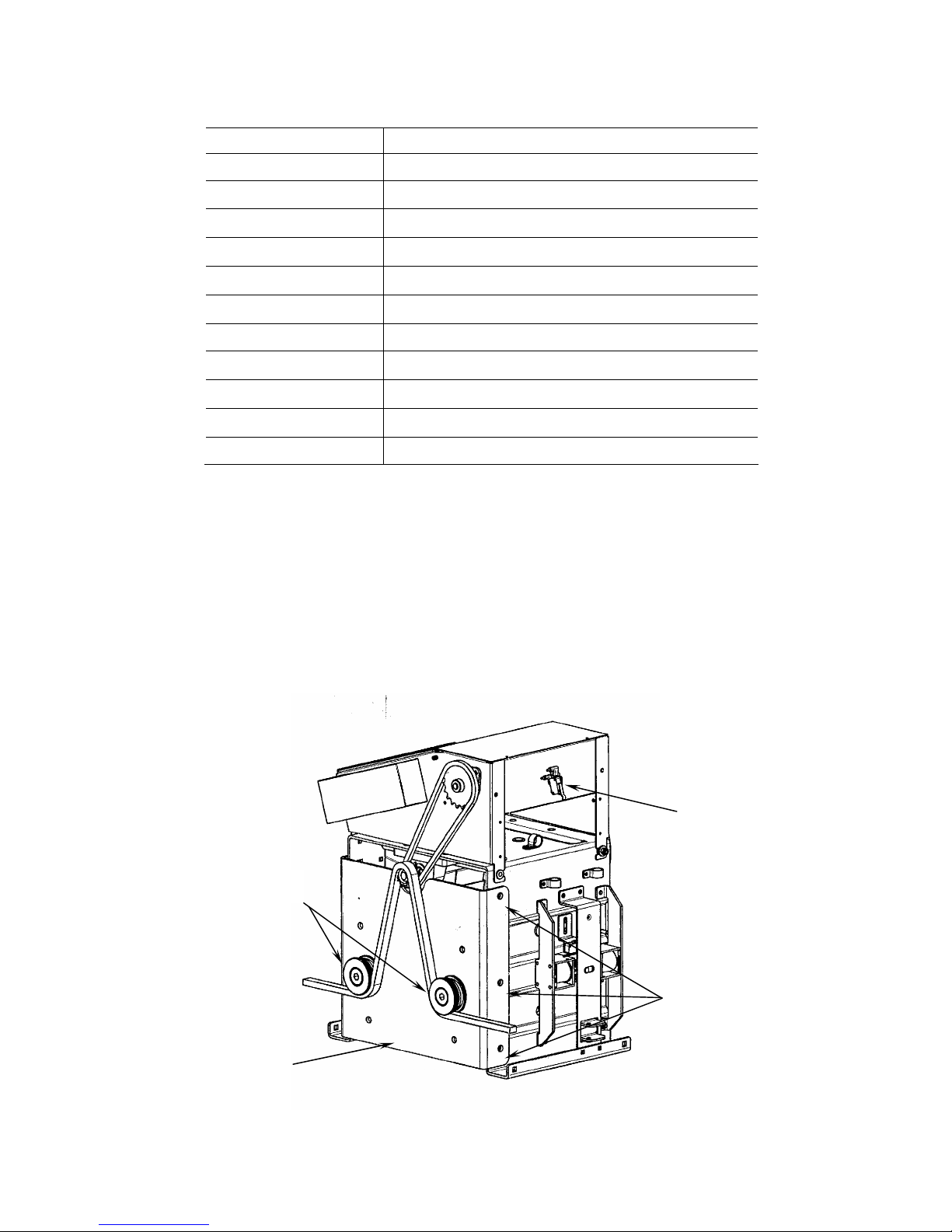
Mount the chain to the gate on one end; then run it under
the first idler, over the main sprocket, and under the
other idler. See Figure 1. Then mount the chain to the
gate on the other end.
To properly adjust the chain mounting and tension, you
must first roll the gate opened and closed to insure
proper alignment.
WARNING! Moving the gate manually before
making a preliminary limit adjustment, can
seriously damage the limit assembly. Please see
the next section before finalizing your chain
mounting.

7
Figure 2. The footprint of the 885 Operator, top view

8
Preliminary Limit Adjustment
Before moving the gate manually with the chain
attached, you must back the limit adjusters off (spin them
toward the center of the adjusting rod)(See Figure 3).
Doing so will insure that you will not bottom them out
on the end of the threaded rod as you move the gate. To
do this, lift the wire retainer while spinning the adjuster.
Once the limits are backed off, you can move the gate by
hand, watching to make sure that the limit adjusters do
not reach the end of the threaded rod as you move open
and closed.
Because the main power has not yet been applied, you
should be able to move the gate by hand. Roll the gate to
the full open and closed positions and make any
adjustments to the chain mounting that are necessary.
Once the chain is properly aligned, move the gate to the
open position and then the closed position to perform a
preliminary limit adjustment. As you move the gate
open, notice that the limit adjusters are moving toward
one of the limit switches. This is your open limit switch.
Lift the wire retainer and spin the closest limit adjuster
toward the open limit switch. Temporarily set it so that
it engages the switch before the gate is all the way open
(6”-12” short of the open position). Be sure that it
triggers the switch early by slowly moving the gate by
hand.
Repeat this procedure in the closed position by setting
the closed limit 6”-12” short as well to be sure that the
gate does not travel too far once power is applied.
Figure 3. The 885 Limit Assemblies
Manual Release
The 885 Operator features a lockable, manual slide lever
that allows you to unlock the gate at any time. As
indicated by the label on the operator cover, the gate is
engaged when the lever is down and disengaged when
the lever is up.
Figure 4. The 885 Operator’s Manual Release
Lever and Lock Solenoid (shown in fail-safe and
fail-secure positions)
The control panel of the 885 operator features a selection
when programming, that allows you to choose whether
the gate will be locked or not in the event of a power
failure. The SO (solenoid, discussed on page 14)
function of the operator gives you two choices:
Y Fail-safe mode: Gate can be moved manually
when power fails.
nFail-secure mode: In the event of a power
failure, you must use the manual release
mechanism for manual operation of the gate.
In addition to the programming choice, the solenoid itself
must be mounted in the proper position for the operator
to function correctly. The solenoid is installed at the
factory in the fail-safe position (shown in figures 4 & 5).
This is the factory recommended position if you are not
using the optional battery backup system (see Optional
Equipment on page 15). Unless you re-mount the
solenoid in the fail-secure position you must choose Y
(fail-safe) on the SO function setting.
Limit Adjusters
Fail-Safe
Fail-Secure

9
Figure 5. The Manual Release Lever and Lock Solenoid (shown in the fail-safe position)
The fail-secure setting is handy in more secure
applications. However, it requires the user to manually
slide the lever to disengage the gate. Because the manual
release lever can be locked (with a padlock, not
included), it may even require the use of a key to
disengage the gate. If your application requires the use
of the fail-secure setting, you will need to follow the
procedure for remounting the solenoid lock.
Solenoid Lock Conversion
WARNING! Turn off the main power before
making any electrical connections or attempting
to perform this conversion.
To convert the solenoid from fail-safe to fail-secure, you
will need a 10mm socket, a small flat blade screwdriver,
and a small pair of external snap ring pliers. Then, refer
to figures 4 and 5, and follow the steps below:
1. Disconnect the two red solenoid wires at the
junction above the solenoid assembly.
2. Remove the solenoid mounting bracket by
removing the two bolts (one on top, one on
bottom) and sliding the assembly to the right.
3. Note the position of the solenoid return springs
(above and below the solenoid pin) and remove
them for safekeeping.
4. Remove the two clip-in nuts that were used to
mount the solenoid bracket and install them in
the new bracket location (two square holes on
the other side of the manual release slide
assembly).
5. Remove the manual release slide assembly (4
bolts) to gain access to the solenoid pin
assembly.
6. Remove the lock pin guide plate (2 carriage
bolts with self-locking nuts).
7. Remove the solenoid pin assembly (nylon slide
block with solenoid pin and lock pin) being
careful not to damage the solenoid switch.
8. Next, remove one snap ring from the lock pin,
slide the pin out, re-insert the pin in the other
side so that it extends the opposite direction,
and re-install the snap ring.
9. Follow steps 7-5 in reverse.
10. Follow steps 3-1 in reverse, keeping in mind
that during step 2, the solenoid mounting
bracket will be installed in the new location on
the left side of the manual release slide
assembly.
The final step will be to set the SO function to n for
fail secure when you get to the programming stage.
Manual Release
Slide Assembly
Manual Release
Lever
Solenoid
Solenoid
Mounting Bracket
Lock Pin
Guide Plate

10
Connect the Main Power
WARNING! Turn off the main power before
you make any electrical connections.
The installer is responsible for providing a dedicated 20
Amp circuit breaker and for making sure that all
electrical wiring and connections conform to all
applicable electrical codes.
By now, the conduit from your power source should be
stubbed up beneath the operator as discussed earlier in
the operator mounting section and shown in Figure 2.
The 885 Operator requires 115 VAC. The 115 volt
power should run through the 2” knockout on the right
side of the operator and be terminated in the junction box
(single gang handy box) mounted slightly above the
knockout, see Figure 6. Remove the blank cover and run
the power wires in through the open fitting on the left
side of the box. Connect the 115-volt line to the black
wire (or the black wire labeled “1”). Connect the neutral
to the white wire (or the black wire labeled “2”).
Connect the ground wire to the yellow wire with the
green stripe. Reinstall the cover on the junction box.
Figure 6. The right side of the 885 Operator
Power Switch and Receptacle
On the top of the 885 Operator (next to the control panel)
there is a main power disconnect switch and a 115-volt
receptacle. The switch controls power to the entire
operator, including the receptacle. The receptacle
provides power for keypads, telephone entry systems,
and other devices that require the use of a plug-in
transformer.
Connect Accessory Devices
WARNING! Turn off the main power before
you make any electrical connections.
Plug-in Loop Detectors
The 885 CAT provides terminals for plug-in Free Exit
and Safety loop detectors. When plugging the detectors
in, be sure that the component side of the detector faces
the display on the 885 CAT. If the installation does not
require the use of one or both detectors, simply leave the
appropriate terminal empty.
The terminal labeled “EXIT LOOP” or “J1” accepts a
detector to serve as a free exit. Plug the detector in and
connect the loop leads to terminals 11 and 12. If you are
using more than one exit loop, connect the loops in series
across terminals 11 and 12. See Figures 7 and 8.
The terminal labeled “SAFETY LOOP” or “J2” accepts
a detector to serve as a safety. Plug the detector in and
connect the loop leads to terminals 9 and 10. If you are
using more than one safety loop, connect the loops in
series across terminals 9 and 10. See Figures 7 and 8.
To activate the Safety Loop Detector you must install a
jumper across terminals 7 and 8, and enable Safety 2 by
choosing Y on the S2 function of the programming. See
the Programming section on page 13.
For more detailed instructions on the loop detectors,
consult the Diablo Controls instruction sheet included
with your operator.
Plug-in Radio Receiver
The 885 CAT provides a terminal for the FAAC plug-in
radio receiver. Simply match the DIPswitches on the
receiver with those on the transmitters and plug it in to
the terminal labeled “DECODER” or “J6”. The receiver
can only be plugged in one way.
Slave Card
There is an optional card that enables you to run two
operators in a master/ slave configuration. It also has six
relays to give you contact closures at different positions.
See the Optional Equipment section on page 16.

11
Connectors J14-Buzzer/ Alarm L.E.D.s
J1-Exit Loop J16-Main Power DL2-Safety 2
J2-Safety Loop J17-Motor DL3-Open A
J3-Encoder DL4-Open B
J4-Slave Card/ Gate State Fuses DL5-Open Limit
J5-Main Terminal F1-1.6A Accessory DL6-Encoder
J6-Radio Receiver F2-12.5A Main Power DL7-Close Limit
J7-Battery Back Up DL8-Stop
J8-Limit Switches Switches/ Buttons DL9-Safety 1
J9-Transformer Primary SW1-+ DL10-Solenoid Lock
J10-Battery Back Up SW2-- DL11-+5 volts
J11-Transformer Secondary SW3-F (Function)
J12-Solenoid Lock SW4-Reset
J13-Cover Stop Switch
Figure 7. The 885 CAT control panel layout
J16 J17

12
Activation Devices
The activating devices for your gate must have normally
open (N.O.) contacts. Connect the normally open (N.O.)
to terminal 1 (Open A) and the common (COM) to
terminal 5 (Common). Multiple devices should be
connected in parallel. The 885 CAT also has a partial
open feature in the A and EP modes. If you have a
certain activation device that you would like to use to
open the gate part way, connect the normally open
(N.O.) to terminal 2 (Open B) and the common (COM)
to terminal 5 (Common). The distance that the gate
opens is determined by the PO (Partial Open) function
that is set during the programming phase. See the
Programming section on page 13.
When using the B or C mode (separate open and close
inputs), terminal 1 (Open A) is the normally open input
to open the gate. Terminal 2 (Open B) is the normally
open input to close the gate.
Safety Devices
The safety devices for your gate must have normally
closed (N.C.) contacts. Connect the normally closed
(N.C.) to terminal 3 (Safety 1) and the common (COM)
to terminal 5 (Common). Multiple devices should be
connected in series.
The way that the 885 responds to a triggered safety
device will depend on how the S1 (Safety 1) function of
the programming is set. See the Programming section
on page 13.
Note: In order to comply with UL325, you must
install two sets of FAAC photobeams, one
inside and one outside.
Stop Devices
The stop devices for your gate must have normally
closed (N.C.) contacts. Connect the normally closed
(N.C.) to terminal 4 (Stop) and the common (COM) to
terminal 5 (Common). Multiple devices should be
connected in series.
Note: If you are not using a stop or safety
device, a circuit must be installed for the control
panel to function normally.
Accessory Power
The 885 CAT control panel provides 24 volt DC to
power accessory devices. There are three positive
outputs (terminals 13, 14, & 15) and three negative
outputs (terminals 16, 17, & 18). Maximum accessory
load is 1.6 amps.
Figure 8. The terminal strip of the 885 Operator

13
LED Indicators
The 885 CAT has ten light emitting diodes that show you
what signals it is being given from the input devices
(open devices, safety devices, limit switches, etc.). The
following table shows the function of each LED.
DL2 Safety 2 Should be on unless the safety
circuit is triggered.
DL3 Open A Should be off unless an
activation signal is being sent.
DL4 Open B Should be off unless a partial
open signal (close signal in B or
C mode) is being sent.
DL5* Open Limit Should be on unless the gate is
open.
DL6 Encoder Comes on each time the optical
reader reads a tooth on the
encoder.
DL7* Close Limit Should be on unless the gate is
closed.
DL8 Stop Should be on unless a stop signal
is being sent.
DL9 Safety 1 Should be on unless a safety
signal is being sent.
DL10 Solenoid
Lock
Shows position of solenoid.
Depends on fail-safe or fail-
secure mounting.
DL11 +5 volts Should be on unless
microprocessor is receiving
inadequate voltage.
* If gate opens to the right DL5 is now the close led and
DL7 is now the open led.
Programming
Programming the 885 is accomplished by using the +, -,
and Fbuttons located near the display on the control
panel. Each time the F button is pressed and held, the
next function is displayed. Each time the F button is
released, the value for that function is displayed and can
be modified with the + and - buttons. As you toggle the
F button through the programming functions, follow the
list below for a detailed description of each function.
Status (the operator status is displayed)
During operation, a number displays the current
status.
00 Closed
01 Opening
02 Stopped (no limit triggered)
03 Open
04 Pause
05 Fail- safe Test
06 Closing
07 Battery On
Be sure to leave the Status function displayed after any
programming changes.
Pause time (selects the pause time before
automatic close from 0 seconds to 4 minutes)
“A” logic only.
Time is adjusted in one-second increments from 0 to 60
seconds. After 60 seconds is reached, time is adjusted in
one-minute increments up to 4 minutes.
Force (selects the motor torque at full speed)
Torque is adjusted from 0 (minimum) to 9
(maximum). The operator starts moving at the
maximum force for approximately 0.8 seconds. The
torque is then reduced to the programmed value.
Note: It is best to start with a force setting of 4
or 5, then adjust it appropriately for the
entrapment protection to work properly.
WARNING! To comply with UL325, the gate
must stop and reverse if it encounters a force of
40 lbs. or more. Be sure that force setting is
adjusted appropriately.
Time Out (selects the maximum motor run
time from 0 to 100 seconds)
Time is adjusted in one-second increments
from 0 to 60 seconds. After 60 seconds is reached, time
is adjusted in 10-second increments up to 1 minute, 40
seconds.
Time out can be calculated by figuring the time it takes
for the gate to run open or close and adding 10%. Either
count the time (in seconds) it takes to open, or do the
math (based on a 1ft./sec speed) to figure the full travel
run time. Then use this formula to figure your time out
setting:
Full travel run time (sec.) x 1.1 = Time out
Logic (selects the operating logic)
There are four operating logics available on the
885 CAT:
AAutomatic mode- Gate opens with an activation
signal, stays open for the programmed pause
time, and closes automatically.
EP Semi-automatic mode- Gate opens with an
activation signal and remains there until another
activation signal is sent, at which time, it closes.
B Guard (manned) mode- Separate open and close
inputs. Use this logic with a 3-button station.
C Constant Pressure mode- Separate open and
close inputs. In this mode you must maintain
the signal throughout the travel or the gate will
stop.

14
Direction (selects the opening direction)
The display for this function shows an arrow
that should point toward the open position.
Choose the appropriate direction for your installation.
Automatic Open (with battery backup only)
Use this feature if you have installed the
optional dc motor, batteries, and battery
backup control unit. Choices are:
YGate automatically opens when power fails.
nWhen power fails, gate remains closed until
open input is given.
Be sure to choose nif you are not using the optional
battery backup.
Automatic Close
This feature is also for use with or without the
optional battery backup. Choices are:
YGate automatically closes when AC power
returns.
nWhen AC power returns, the gate remains open
until an input is given.
Be sure to choose nif you are not using the optional
battery backup.
Solenoid (selects the operation of the manual
release solenoid)
YFail-safe mode: Gate can be moved manually
when power fails.
nFail-secure mode: In the event of a power
failure, you must use the manual release
mechanism for manual operation of the gate.
The manual release solenoid must be mounted properly
for your selection (see the Manual Release section on
page 8). The 885 Operator comes with the solenoid
mounted for fail-safe mode.
Alone (This is a new function that is not yet
incorporated in the software of the 885 CAT.)
YBe sure to choose this setting.
nDo not use. Will cause the control panel not to
function.
Slave (selects master or slave operator in a
master/ slave configuration)
Yslave operator
nmaster operator
If you chose Yon the previous function (stand-alone), be
sure to choose n(master) now.
Fail-safe test (photo beam operational test)
This is a European safety test that tests the
photobeams before every cycle. In the U.S. it
is typically left disabled.
Yenabled
ndisabled
Safety 1 (selects the function of the safety 1
input on terminal 3)
OC Opening: Gate stops when safety device is
triggered and closes when safety device is
cleared.
Closing: Gate stops when safety device is
triggered and opens when safety device is
cleared.
CL Opening: No effect
Closing: Gate re-opens when safety device is
triggered.
Partial opening (Open B input at terminal 2)
Selects the distance of the partial opening from
0.5 meters to 5 meters in 0.5 meter increments.
Leaving the setting at 0 disables the partial opening
feature. 1 meter = 39 inches.
Safety 2 (Use this function to enable or disable
the plug-in safety loop detector).
Ysafety 2 (plug-in detector) is used
nsafety 2 (plug-in detector) is not used.
If you are using the plug-in safety loop detector, be sure
to jump terminal 7 to 8 as well.
Safety 2 (device selection)
This is a new function that is not yet
incorporated in the software of the 885 CAT.
Be sure to choose the Lsetting.
FDo not use. Will cause the control panel not to
function.
L Be sure to choose this setting.

15
Safety 2 (selects how the plug-in safety loop
detector will affect the gate’s operation)
OP Opening: Gate stops when safety device is
triggered and closes when safety device is
cleared.
Closing: No effect
CL Opening: No effect
Closing: Gate re-opens when safety device is
triggered.
OC Opening: Gate stops when safety device is
triggered and closes when safety device is
cleared.
Closing: Gate stops when safety device is
triggered and opens when safety device is
cleared.
After you have made all your programming selections
and run the gate at least one full cycle at full speed, you
must toggle through each function again to lock them in
to the memory. This will also give you an opportunity to
double-check the setting of each function. It is best to
leave the display showing the St (Status) function so that
the status of the gate will always be displayed.
Note: If you find the display showing two red
dots, this is a power saving mode. The display
will return if you push the + or - buttons.
Test the System
Once you have connected main power, connected the
accessory devices, and programmed the 885, you can test
the gate system.
WARNING! If you have not performed a
preliminary limit adjustment (discussed on page
7), do so before testing the operator.
With the gate in the closed position, turn on the main
power and check the status of the LED indicators. See
LED Indicators on page 13. Correct any problems with
your input devices if necessary. Once the LEDs are
illuminated properly, make sure that the gate path is
clear, and give the 885 an activation signal. The gate
should run open slowly as it looks for the open limit. If
you are in the automatic mode, the gate should time out
and close after the programmed pause time. If you are in
any other mode, give the operator a close signal. The
gate should run closed slowly as it looks for the closed
limit.
The initial cycle is a learning mode in which the gate will
run slow as it searches for the limit switches. Once it is
complete, the operator will run at full speed.
Continue to cycle the gate and test all input devices. Be
sure that all safety devices are functioning properly.
Entrapment Protection
The 885 Operator features an entrapment protection
system. It incorporates an optical encoder, which
monitors the gate’s movement, along with an adjustable
force output and an audible alarm to warn you when the
gate encounters something or someone.
WARNING! The entrapment protection system
will not function properly if the force setting
(see Programming on page 13) is not set
properly. It must be set strong enough to move
the gate consistently, but be able to be stopped
if it encounters a force of 40 lbs. or more.
WARNING! The entrapment protection
system must be adjusted to function properly to
comply with UL325.
Encoder
The encoder is a device that monitors that movement of
the gate. It determines when the gate will slow down
before triggering a limit and when the gate has
encountered an obstruction. If it senses that the gate has
stopped moving without a limit being triggered, the gate
will invert movement and run slowly the other way.
Audible Alarm
The 885 features an audible alarm that will sound if the
gate encounters two sequential obstructions in the same
cycle. For example: The gate is running closed and
encounters an obstruction. The encoder senses this and
immediately re-opens the gate. If the gate encounters
another obstruction before reaching the open limit, the
gate will stop and the alarm will sound. The main power
must be reset before the operator will be ready for
another signal.
Final Limit Adjustment
Once the system has been tested thoroughly and
everything is functioning properly, you will need to fine-
tune the limit adjustments. Following the same steps as
you did during the preliminary limit adjustment, fine-
tune the position of the limit adjusters. See Figure 3. If
the gate stops too soon, back the limit adjuster off. If it
goes too far, turn it toward the limit switch. Make small
adjustments and cycle the gate after each adjustment to
check the result.

16
Optional Equipment
The following optional items are available for your 885
Operator.
Slave/Relay Card
The 885 Slave/Relay card is a device that allows you to
obtain the following features.
1) Slave: Enables two opposing operators to
operate simultaneously, preventing any lag time
between the gates when a signal is sent to the
operators to open.
2) Relay: Provides eight normally open (N.O.)
contacts for connecting extra equipment, such
as lighting controls, counters and so forth.
The slave/relay card plugs into the master 885’s control
panel (J1).
Plugging the card into the master 885 control panel and
then wiring the two boards together as shown in Figure 9
achieves the master/slave configuration.
The slave will then react as the master does.
The following things must be done in the programming
stages to insure the proper operation of both the master
and slave operators.
1) The master unit must be installed on the longer
leaf.
2) Set the slave unit time out equal to the time set
on the master.
3) The safety devices must be connected to the
master unit.
4) Program the following function on the master
operator.
“Stand Alone” AL Y
“Slave” SL N
5) Program the following function on the slave
operator.
“Stand Alone” AL Y
“Slave” SL Y
6) If you are in “A” mode and have a jumper
placed between terminals two and five than set your
slave machines pause time to 00 Seconds.
Note: The slave unit provides, to the master, the
following information.
Limit switch activation: During opening or closing
movements, the master unit waits for the slave to end its
cycle. (Limit switch engaged).
Entrapment device activation: When the slave unit
detects an entrapment, the movement reverses both
operators.
Each terminal on the card along with the common
terminal (labeled -) provides a contact with a maximum
rating of 1 amp for a 30VDC accessory, each contact
closes under a certain condition of the gate leaf. Use the
following chart to achieve the desired activation.
Pin 1 Gate closed
Pin 2 Opening
Pin 3 Open (No limit switch engaged)
Pin 4 Opened
Pin 5 Pause Time
Pin 6 Fail Safe
Pin 7 Closing
Pin 8 Power failure and gate stopped
(Battery Use)
Pin - Contact Common
Figure 9. Slave Card Wiring
Note: Apply the jumper wire between terminals two and
five when using “A” mode only.

17
Battery Back Up System
When installed, this system will provide battery power in
the event of a loss of AC power. How it will function
depends on two things:
1. Which logic you are running in (A, EP, or C).
2. If you choose “Y” or “n” for the AO (Automatic
Open) function in the programming of the
885CAT control panel.
If you are running in A or EP mode it will function as
follows:
Automatic Open enabled (select Y for the AO function
of the programming)
When AC power fails, the battery back up instantly
sends power to the control panel. The gate opens after a
short delay and remains open. Once power returns, one
of two things will happen, depending on whether you
have the AC (Automatic Close) function enabled or
disabled. If you have chosen “Y” for the AC function,
the gate will close automatically. If you have chosen “n”
for the AC function, the gate will remain open, but be
ready for a close signal.
Automatic Open disabled (select “n” for the AO
function of the programming)
When AC power fails, the battery back up instantly
sends power to the control panel and it is ready for an
open signal. If a signal is not received right away, the
panel “sleeps” until a signal is received. A signal will
wake the system up and open the gate. In this mode
(Automatic Open disabled), you can continue to open
and close the gate as long as the batteries are charged.
Whether you are running in A or EP logic under normal
power makes no difference. When running on battery
power, the gate will operate in EP mode. The number of
cycles that you can run with fully charged batteries will
depend on the length of your gate.
If you are running in C mode it will function as follows:
Whether you have the Automatic Open (AO) function
enabled or disabled makes no difference. When AC
power fails, the gate will not automatically open. The
battery back up instantly sends power to the control
panel and it is ready for an open signal. You can open
the gate one time and then the back up will shut down
until AC power is restored.
When running on battery power the photobeams will
function normally in any logic. The inherent entrapment
will function, although slightly different than under
normal AC power. If the gate is obstructed while
running under battery power, it will stop and the alarm
will sound. Another open signal will silence the alarm
and the gate will continue in the same direction.
Battery Back Up Installation
WARNING! Turn the main power to the operator
off before performing any of the tasks involved in
installing the battery back up system. This
installation should be performed by qualified
personnel only. When you open the battery back up
system, the box should contain the following:
1- DC Motor
1- Battery back up control panel
2- 12-volt batteries
1- Cross brace for operator chassis
1- Battery tray
1- Set of battery wires
1- 6-wire interface cable
1- 8-wire ribbon cable
1- Drive belt
4- M6 x 20mm carriage bolts
8- M6 flat washers
8- M6 self-locking nuts
1- Pulley
1- M4 x 12mm bolt
1- M4 fender washer
1- Feather key
2- 16mm wire chase nipples
4- Snap-in standoffs
2- M8 x 20mm hex bolts
2- M8 self-locking nuts
The tools needed for installing the battery back up
system are as follows:
3mm Allen wrench
Small flat blade screwdriver
10 mm Socket
13 mm socket
13 mm open end wrench
To install the battery back up system, follow the steps
below and refer to figures 10 and 11.
1. If you haven’t done so already, turn off the main
power.
2. Remove the existing drive belt.
3. Mount the DC motor in the location shown in
figure 11. Secure it with 4 each of the 6mm flat
washers and self-locking nuts.
4. Run the DC motor wires through the wire chase
directly above the DC motor. If there is not a
plastic nipple already installed in the hole, insert
one of the 16mm chase nipples that was provided
with the system. Reach in the left side of the
operator, under the control panel tray to grab the
wires and feed them up into the control panel area.

18
5. Insert the battery tray in the large square hole on
the right side of the operator. The round holes on
the two straps that extend upward from the tray will
line up with the square holes on the operator.
Install the 4 carriage bolts from the inside out and
secure with the remaining flat washers and self-
locking nuts.
6. Install the feather key into the key way of the dc
motor’s output shaft. Slide the pulley on and
secure with the 4mm fender washer and bolt.
7. Install the new (longer) drive belt. Put the drive
belt behind the main pulley for ease of installation.
8. Once the drive belt is installed, mount the cross
brace across the bottom of the operator (mounting
points shown in Figure 11) with the 8mm hex bolts
and self-locking nuts.
9. Run the two battery wires up through the empty
wire chase above the battery tray. If there is not a
plastic nipple already installed in the hole, insert
one of the 16mm chase nipples that was provided
with the system. Reach in the left side of the
operator, under the control panel tray to grab the
wires and feed them up into the control panel area.
Leave enough slack for the four connectors to be
plugged into the batteries before the batteries have
been slid into the tray. Do not install the batteries
yet.
10. Reach in the left side of the operator, under the
control panel tray and install the four snap-in
standoffs for the battery back up control panel.
Snap them in from the bottom up in the holes
provided next to terminal 1 of the 885 CAT.
11. Install the battery back up control panel so that the
four wiring terminals face the gate leaf.
12. Connect the battery and motor wires as shown in
figure 10.
13. Plug the 8-wire ribbon cable into J10 on the battery
back up panel and J10 on the 885 CAT.
14. Plug the 6-wire interface cable into J7 on the
battery back up panel and J7 on the 885 CAT.
15. Turn AC power back on.
16. Plug the batteries in; red to positive, black to
negative. The jumper should connect the negative
of one battery with the positive of the other
(batteries are wired in series because it is a 24 volt
system). Slide the batteries into the battery tray.
Figure 10. The battery back up control panel
Figure 11. The 885 Operator with the Battery Back Up System installed.
Control Panel
Tray
AC Motor
Cross Brace
DC Motor Drive Belt
Battery Tray
Batteries
Blk
Red
+
-
Moto
r
Battery

19
Maintenance
WARNING! Turn the main power to the
operator off before performing any maintenance
or repairs. The manufacturer recommends that
only qualified personnel check and maintain the
equipment.
The 885 Operator
The FAAC recommended maintenance schedule vary
according to the frequency of use of the operator,
whether lightly used (once or twice an hour) or heavily
used (many cycles per hour). Operators used in a humid/
salt air climate should follow the heavy use schedule.
Lubricate the chain and gate rollers.
Use a light, spray on lubricant (teflon, silicon, WD-40,
etc.) to lubricate the entire chain. Grease the gate rollers
appropriately for the type of rollers that you have.
CAUTION! Do not use heavy grease to
lubricate the chain. It will collect dirt and
debris, which could damage the chain and/or
drive sprockets.
Light duty use: every 6 months
Heavy-duty use: every 3 months
Check entrapment protection devices.
Test the photobeams to ensure that the gate responds
properly to a potential obstacle. Also check to see if the
inherent entrapment protection (reverse on contact)
system is functioning properly. The gate should invert
movement if it encounters a force of 40 pounds or more.
Light duty use: every 12 months
Heavy-duty use: every 6 months
Test the batteries.
If you are using the optional battery back up system,
check your batteries to ensure that they are charged.
Light/ Heavy duty use: every 12 months
The 885 CAT Control Panel
Keep the control panel free from spider webs, insects,
etc. Otherwise, the control panel requires no
maintenance.
Troubleshooting
WARNING! Turn the main power to the
operator off before performing any maintenance
or repairs. The manufacturer recommends that
only qualified personnel check and maintain the
equipment.
Problem: When an activation signal is sent, the open
light (DL3) comes on, but the gate does not open.
Possible Solutions:
1. Check to see if the stop light (DL8) is
illuminated. If not, check the cover safety
switch and all other stop devices.
2. If either safety input (Safety 1 or 2) is
programmed to be active in the opening
direction, check to see that the Safety 1 light
(DL9) and the Safety 2 light (DL2) are
illuminated. If they are not, check your safety
devices.
3. Check to see that the Lock Solenoid is retracting
and triggering its switch when the signal is
given. When the switch is triggered it will
illuminate the DL10 led.
Problem: Gate opens, but will not close.
Possible Solutions:
1. Check the logic setting in the programming. If
in A mode gate should close after selected pause
time. In any other mode a close signal is
required.
2. If either safety input (Safety 1 or 2) is
programmed to be active in the closing
direction, check to see that the Safety 1 light
(DL9) and the Safety 2 light (DL2) are
illuminated. If they are not, check your safety
devices.
3. Check to see that the control panel knows that
the gate is open. Make sure that the open limit
light (DL5) is not illuminated. Make sure that
the display shows 03 or 04.
Problem: Gate starts it’s travel (open or close) but does
not make it all the way.
Possible Solutions:
1. Check to see that a limit isn’t being triggered
prematurely. Check the limit lights (DL5 and
DL7). Check the status display.
2. Check to see that the Safety 1 light (DL9) and
the Safety 2 light (DL2) are illuminated. If they
are not, check your safety devices.
3. Check to see that the operator is able to pull the
gate. Increase the force setting if necessary.
Adjust the gate and rollers if necessary.

20
Problem: When the safety devices are triggered, the
gate does not respond, as it should.
Possible Solutions:
1. Check to see that your safety devices are
connected properly. Photocells should be
connected in series across terminals 3 and 5.
Terminals 7 and 8 should be jumped for the
plug-in loop detector to work properly.
2. If the plug-in loop detector is the problem, make
sure that the S2 function is set to Y.
3. Check to see if you have chosen the proper
settings for the S1 and FU functions.
Problem: There are no LEDs illuminated on the control
panel.
Possible Solutions:
1. Check for 115 volts at the operator’s junction
box. If you do not have power there, check the
main breaker.
2. Make sure the power switch on the top of the
operator is on.
3. Check the F1 and F2 fuses on the control panel
with an ohm meter or continuity tester.
4. Make sure that the transformer is connected
properly to the control panel at J9 and J11.
When troubleshooting any problem with the 885
Operator, the ability to interpret the LED indicators will
assist you more than anything. Using the table on page
13 will help narrow down most problems.
A volt-ohm meter (VOM) or a multimeter is also a big
part of troubleshooting. It will give you the ability to
check voltage, resistance, continuity, etc.
If you have a problem with the 885 Operator and these
general solutions don’t solve it, contact your dealer or
distributor for assistance. If you need further assistance,
FAAC offers the best technical support in the industry
and you can reach a technician by calling 800-221-8278
or e-mail us at faactech@vcn.com.
Table of contents
Other FAAC Gate Opener manuals

FAAC
FAAC 411 User manual

FAAC
FAAC Estate Swing User manual

FAAC
FAAC Estate Swing E-S 1600 Series User manual

FAAC
FAAC Safe Zone S418 User manual

FAAC
FAAC 415 Series User manual

FAAC
FAAC T-MODE TM 45 P&P User manual

FAAC
FAAC 844 User manual

FAAC
FAAC Estate Swing e-sU 2200 series User manual

FAAC
FAAC S800H ENC User manual

FAAC
FAAC 415 Series User manual
Popular Gate Opener manuals by other brands

Nice Apollo
Nice Apollo HYPPOETL installation manual

Atecnica
Atecnica B320 INSTRUCTIONS AND RECOMMENDATIONS FOR THE INSTALLER

Avidsen
Avidsen 114461 manual

AES
AES i-GATE 20 installation manual

Manaras Opera
Manaras Opera Opera-GH Installation and instruction manual

GFA
GFA 10003831 10012 installation instructions