INDEX
1.2 Installation
1.2.1 Standard Installation
1.2.2 Dimension Chart
1.2.3 Components of Installation
1.2.4 Installation of Articulated Arm Opener
1.2.5 Emergency Release
1.2.6 Wi-Fi Device (Sold Seperately)
1.2.7 Photocells (Sold Seperately)
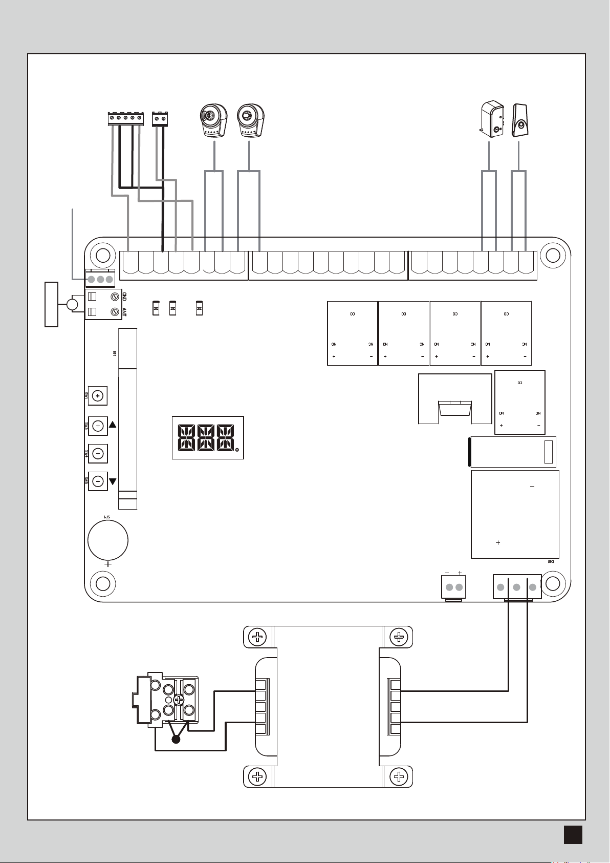
1.2.8 Power Supply Connections
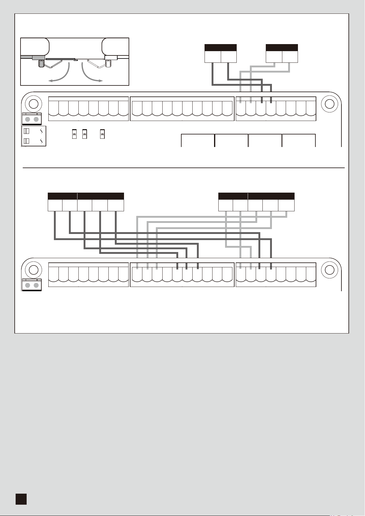
2.1 Wiring Connection
2.1.1 Master Motor is installed at right side
2.1.2 Master Motor is installed at left side
3. Get Started
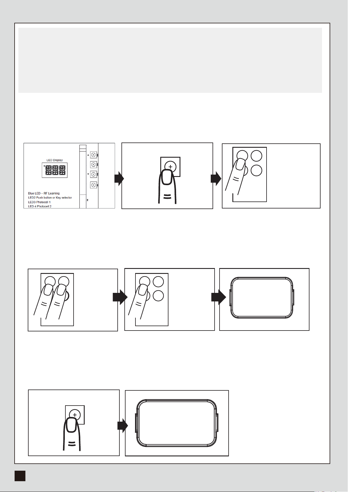
3.1 Step 1: Remote Memorizing
3.1.1 Memorizing
3.1.2 Remote learning without control board
3.1.3 Deleting all memory of all remotes
3.2 Step 2: System Learning
3.3 Gate-moving Logic
3.4 Checking the Gate Movement
3.5 LED Indication
3.5.1 Function of the LED Display
3.6 Parameter
3.6.1 Parameter Learning
3.6.2 Parameter
3.6.3 Photocell Logic
4. Dimension
5.Technical Features
6.Maintenance
1
1
1
2
2
3
3
4
4
5
6
7
8
8
8
8
8
9
10
10
10
10
11
11
11
14
15
16
16
1.1 Warnings
WARNING :
This user manual is only for qualified technicians who is specialized in installations and automations.
(1) All installations, electrical connections, adjustments and testing must be performed only after
reading and understanding of all instructions carefully.
(2) Before carrying out any installation or maintenance operation, disconnect the electrical power
supply by turning off the magneto thermic switch connected upstream and apply the hazard area
notice required by applicable regulations.
(3) Make sure the existing structure is up to standard in terms of strength and stability.
(4) When necessary, connect the motorized gate to reliable earth system during electricity connection phase.
(5) Installation requires qualified personnel with mechanical and electrical skills.
(6) Keep the automatic controls (remote, push bottom, key selectors…etc) being placed properly
and away from children.
(7) For replace or repair of the motorized system, only original parts must be applied. Any damage
caused by inadequate parts and methods will not be claimed to motor manufacturer.
(8) Never operate the drive if you have any suspect with what it might be faulty or damage to the system.
(9) The motors are exclusively designed for the gate opening and closing application, any other
usage is deemed inappropriate. The manufacture should not be liable for any damage resulting
from the improper use. Improper usage should void all warranty, and the user accepts sole
responsibility for any risks thereby may accrue.
(10) The system may only be operated in proper working order. Always follow the standard procedures
by following the instructions in this installation and operating manual.
(11) Only command the remote when you have a full view of the gate.
Please keep this installation manual for future reference.
7.Technical Support 17