Vdwall LVP909 Series Technical manual

LVP909 operation instruction
Contents:
1………………………………………………….Signal switch buttons
2………………………………………………….Output channel selection buttons
3………………………………………………….User setup buttons
4………………………………………………….Function buttons
5………………………………………………….Power switch and socket
6………………………………………………….Software control port
7………………………………………………….Output ports
8………………………………………………….Input ports
9………………………………………………….Sending card slot

10…………………………………………………Setting language
11…………………………………………………Setting output resolution
12…………………………………………………Application mode configuration
13…………………………………………………Setting output width and height (App 1)
14…………………………………………………Setting output width and height (App 2 3 4)
15…………………………………………………Setting output width and height (App 5 6)
16…………………………………………………Configuring input source for App5 6
17…………………………………………………Setting PIP (POP)
1. Signal switch buttons
1.1. LVP909 has 6 channels of input port: V1 V2 VGA DVI HDMI SDI;

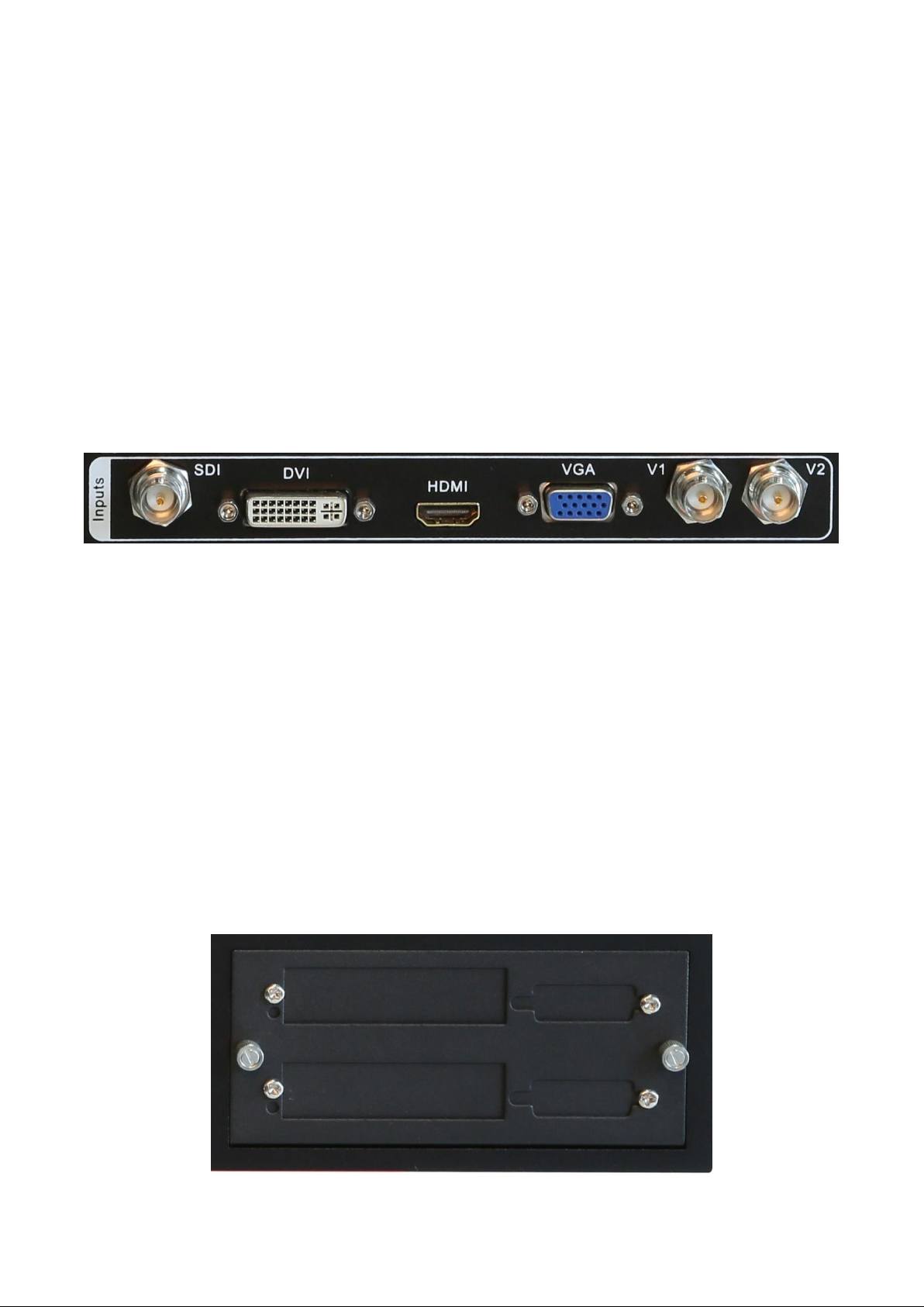
1.2. after connecting input video source, you need LVP909 outputs which one
press relative signal button, for example we need HDMI output, press HDMI
button LVP909 outputs HDMI video source, of course you have connected
HDMI source to the input port;
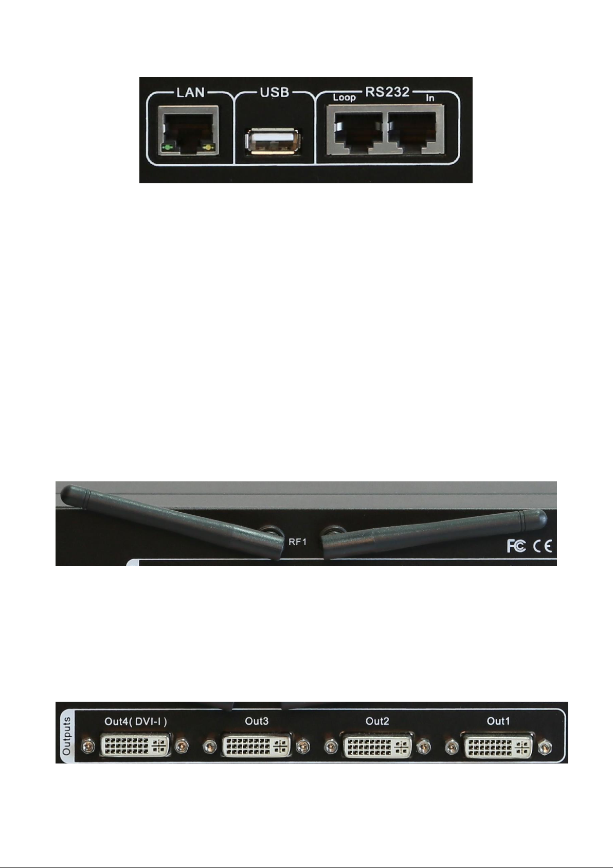
2. Output channel selection buttons
2.1. LVP909 has 4 output ports Out1 Out2 Out3 Out4, when configure output
port parameters in user menu press relative button to select output port then
configure it;
2.2. LVP909 has 4 image layers (which in application mode 5 6 is available) the
image layer buttons are IMG1 IMAG2 IMAG 3 IMG4, when configure

image layer parameters in user menu press relative button to select image
layer then configure it
3. User setup buttons
3.1. Knob OK: when configuring parameters value rotate it to change or increase
and decrease parameter value;
3.2. Brt+: after entering user setup menu, press it to select next setup option
( when not in setup configuration state press it to increase brightness);
3.3. Brt-: after entering user setup menu, press it to select last setup option ( when
not in setup configuration state press it to decrease brightness);
3.4. Setup: press it to enter user setup menu;

3.5. : return button, after entering setup menu press it to exit setup menu;
4. Function buttons
4.1. PIP: PIP (picture in picture) function switch;
4.2. M1 M2 M3 M4: memory buttons, LVP909 can save 4 modes in advanced (when
in application mode 1 save 4 mode for PIP, when in another mode can save 4
modes for output port parameters);
4.3. Take: quick switch button, when LVP909 has opened quick switch function,
after pre-selecting a video source press the button can let the pre-select video

source output quickly;
4.4. C/F: switch effect selection button ( seamless switching, fade in and fade out
switching);
4.5. Auto: VGA signal automatically adjust button, when input VGA source to
LVP909 and the video on LED screen not in the correct location and has some
display problem, press the button to adjust VGA input source let it OK;
4.6. Lock: press the button to open lock function, after opening all the buttons can’t
work, press Lock button 3 times to unlock;
4.7. Info: press it you can refer the system information of LVP909 displaying on LCD
screen on front panel;
5. Power switch and socket
6. Software control port

6.1. LVP909 has 3 software control ports LAN USB RS232;
6.2. After connect control cable to computer, open the control software on PC,
must select correct port on PC, for example we connect control cable to PC’s
COM1 port, in control software you must select COM1 port;
6.3. Wifi antenna: LVP909F has Wifi control function, first install APP on mobile
phone then open wifi of phone to find LVP909 wifi then connect it, after
connecting you can open APP on phono to control LVP909F by Wifi function;
7. Output ports

7.1. LVP909 has 4 output prots, Out1 Out2 Out3 Out4;
7.2. Out4 ( DVI-d) support output GAV format, so you can use DVI to VGA cable to
connect the port to a monitor with VGA input port;
8. Input ports
8.1. LVP909 has 6 channels of input port SDI DVI HDMI VGA V1 V2,
connect relative format video source to relative input port, for example Laptop
VGA to connect VGA port;
9. Sending card slot

9.1. LVP909 can put two common sending cards inside, normally common sending
card only has two RJ45 ports;
10. Setting language
10.1. Press power switch to open processor, then you can see the interface as below;
10.2. Press Setup button to enter user setup menu, press Brt- button to select 6. 语
言/language,press OK to enter language setup menu;
10.3. After entering language setup menu, rotate OK to select 6.1. 语言/Language
English, then press OK to confirm, press return button to exit user setup menu;
输入: VGA
输入状态: 1366x768_60
--------------------------------------------------------------------
输出位置大小: (0,0,1920,1080)
--------------------------------------------------------------------
切换方式: 一键直接切换
切换效果: 无缝直切
应用模式: AppM1(切换器)
设置
--------------------------------------------------------------------
1.输出端口配置 >>
2.输出图像 >>
3.输入信号 >>
4.图像画质 >>
5.通讯 >>
6.语言/Language >>
7.高级 >>

11. Setting output resolution
11.1. Press Setup button to enter user setup menu, press Brt+ button to select 1.
Output CFG, press OK to enter configuration menu;
11.2. Press Brt+ button to select 1.1 Resolution 1920 x 1080_60, rotate OK to
select destination output resolution, after selectin resolution press Brt- button
to select 1.3 Setup press OK to confirm;
6. 语言/Language
--------------------------------------------------------------------
6.1. 语言/Language English
Setup
--------------------------------------------------------------------
1.Output CFG >>
2.Output Image >>
3.Input Video Signal >>
4.Color & Brightness . etc. >>
5.Coummunication >>
6.语言/Language >>
7.Advanced >>

11.3. normally the output resolution must be bigger than the actual resolution of
LED screen or equal, for example the LED screen ( resolution 1792 X 1056)
which connects to Out 1, so the output resolution we set must be bigger than
this one, 1920 x 1080 resolution will be ok for this;
12. Application mode configuration
12.1. Press Setup button to enter user setup menu, press Brt+ button to select 1.
Output CFG, press OK to enter configuration menu;
12.2. Press Brt- button to select 1.2 App Mode, rotate OK to select the proper
application mode you need, after selectin resolution press Brt- button to select
1.3 Setup press OK to confirm (LVP909 has 6 application modes);
Output CFG
--------------------------------------------------------------------
1.1 Resolution 1920x1080_60
1.2 App. Mode AppM1 ( Switcher )
1.3 Setup OK To Apply
--------------------------------------------------------------------
Out1 =Out2 = 1 Program
( Switcher )
Out3 = No Output
Out4 = Pre + Sync. Monitor

12.3. Application mode 1:
Out1 = Out2 = 1 program
(switcher)
Out3 = No Output
Out4 = Pre + Sync. Monitor
12.4. Application mode 2:
Out1 + Out2 = 2 program
(2 Mosaic)
Out3 = No output
Out4 = Pre + Sync. Monitor

12.5. Application mode 3:
Out1 + Out2 + Out3 = 3 program
(3 Mosaic)
Out4 = Sync. Monitor
12.6. Application mode 4:

Out1 + Out2 + Out3 + Out4 = 4 program
(4 Mosaic)
No Monitor Output
12.7. Application mode 5
Out1 = Out2 = 1 program
(4 image)
Out3 = No Output
Out4 = Sync. Monitor

12.8. Application mode 6
Out1 = Out2 = 1 program
(3 image)
Out3 = No Output
Out4 = Input Sync. Monitor

13. Setting output width and height (App 1)
13.1. Press Setup button to enter user setup menu, press Brt- button to select 2.
Output Image, press OK to enter output image setup menu;
13.2. Press Brt- or Brt+ button to select setup 2.1 Out Width and 2.2 Out Height,
rotate OK to configure parameters, press OK to save parameters ( the output
width and height must be as same as the width and height of your actual LED
screen);
13.3. In the setup menu In width and height, In H-start and V-Start used to crop the
area of input video source then output the area, normally we don’t use it;
Setup
--------------------------------------------------------------------
1.Output CFG >>
2.Output Image >>
3.Input Video Signal >>
4.Color & Brightness . etc. >>
5.Coummunication >>
6.语言/Language >>
7.Advanced >>
2. Output Image (Out1) AppM1
--------------------------------------------------------------------
2.1 Out Width 1920
2.2 Out Height 1200
2.3 Out H_Start 0
2.4 Out V_Start 0
2.5 In Width 1920
2.6 In Height 1200
2.7 In H_Start 0
2.8 In V_Start 0

14. Setting output width and height (App 2 3 4)
14.1. Press Setup button to enter user setup menu, press Brt- button to select 2.
Output Image, press OK to enter output image setup menu;
14.2. Application mode 2 3 and 4 especially used for splicing large LED screen, so in
the menu we need to configure whole LED screen resolution, unit LED screen
resolution and input H and Y start;
14.3. In application mode 2 3 4 before setup we can press M1 M2 M3 or M4 to select
a mode to save these parameters;
14.4. For example we have a LED screen 3840 x 1080, and two unit LED screens 1920
x 1080;
14.5. Press Brt+ or Brt- button to select setup option 2.1 LED Total Width and 2.2
LED Total Height, then configure it being total width 3840, total height 1080;
14.6. Press Brt+ or Brt- button to select setup option 2.4 Unit Width and 2.5 Unit
Height, then configure it being unit width 1920, unit height 1080;
2. Output Image (Out1) AppM2 M1
--------------------------------------------------------------------
2.1 LED Total Width 1920
2.2 LED Total Height 1200
2.3 Output Port Out1
2.4 Unit Width 1920
2.5 Unit Height 1200
2.6 Unit H_Start 0
2.7 Unit V_Start 0
2.8 Auto Calculation OK To Apply

14.7. After configuring total and unit parameters, press Brt+ or Brt- button to select
2.8 Auto Calculation, press OK to apply it;
14.8. After last step some output ports we need to configure the 2.11 In H_Start or
2.12 In V_Start parameters, for example out2 3 4, set the parameters is to let
LVP909 the output port to crop the input video source from where;
14.9. After configuring Out1 press Out2 button to select Out2 then configure it, press
Out 3 or Out4 button can select them then configure them;
15. Setting output width and height (App 5 6)
15.1. After LVP909 configuring App M5, then you can see the interface as below;
2. Output Image (Out1) AppM2 M1
--------------------------------------------------------------------
2.9 In Width 1920 1920
2.10 In Height 1200 1200
2.11 In H_Start 0 0
2.12 In V_Start 0 0
2.13 Out Width 1920 1920
2.14 Out Height 1200 1200
2.15 Out H_Start 0 0
2.16 Out V_Start 0 0
Image_1 Source: VGA
Image_1 Status: 136 x 768_60
Image_2 Source: VGA
Image_2 Status: 136 x 768_60
Image_3 Source: VGA
Image_3 Status: 136 x 768_60
Image_4 Source: VGA
Image_4 Status: 136 x 768_60
--------------------------------------------------------------------
App. Mode: AppM5 Image2-1-4-3 0 s

15.2. Press Setup button to enter user setup menu, press Brt- button to select 2.
Output Image, press OK to enter output image setup menu;
15.3. Press Brt+ or Brt- button to select setup option, rotate OK to change
parameters, press OK to save;
15.4. Before setting parameters press M1 M2 M3 or M4 to select a mode to save
these parameters in one mode;
16. Configuring input source for App5 6
16.1. Press Setup button to enter user setup menu, press Brt- button to select 3.
Input source, press OK to enter input source setup menu;
2. Output Image (Image_2) AppM5 M1
--------------------------------------------------------------------
2.1 Out Width 1920
2.2 Out Height 1200
2.3 Out H_Start 0
2.4 Out V_Start 0
Setup
--------------------------------------------------------------------
1.Output CFG >>
2.Output Image >>
3.Input Source >>
4.Color & Brightness . etc. >>
5.Coummunication >>
6.语言/Language >>
7.Advanced >>

16.2. Press Brt+ or Brt- button to select setup option, rotate OK to select input
source, press OK to save;
17.Setting PIP (POP)
17.1. Press PIP button to open the function, then you can see the interface as below;
17.2. Press Setup button to enter PIP parameter configuration menu, press Brt+ or
Brt- to select setup option D.1 Image_1 source or D.2 Image_2 source, rotate
OK to configure input video source, press OK to save;
3. Image Source AppM5 M1
--------------------------------------------------------------------
3.1 Image_1 Source V1 V2 VGA
DVI HDMI SDI
3.2 Image_2 Source V1 V2 VGA
DVI HDMI SDI
3.3 Image_3 Source V1 V2 VGA
DVI HDMI SDI
3.4 Image_4 Source V1 V2 VGA
DVI HDMI SDI
Image_1 Source: VGA
Image_1 Status: 136 x 768_60
Image_2 Source: VGA
Image_2 Status: 136 x 768_60
--------------------------------------------------------------------
Image_1 Pos.& Size: (o, 240,956,720)
Image_2 Pos. & Size: (964,240,956,720)
Display Mode M1
App. Mode: AppM1(Switcher)
Image2->1: O s
Other manuals for LVP909 Series
1
Table of contents
Other Vdwall Power Distribution Unit manuals