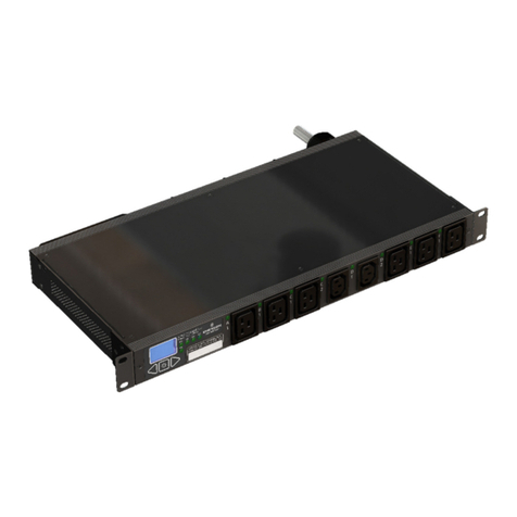
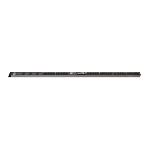
Emerson Liebert MPX PRC User manual

DEUTSCH ENGLISH
Rack PDUs Mounting Options Index b Seite / Page 1
(ECR no. 15302)
Inhalt Content
Emerson Network Power Rack PD
Us
Montagemöglichkeiten / Mounting Options
■ Racks & Integrated Cabinets

DEUTSCH ENGLISH
Rack PDUs Mounting Options Index b Seite / Page 2
(ECR no. 15302)
Inhalt Content
1. Bitte beachten Sie...................................... 4
1.1. Allgemeine Hinweise................................ 4
1.2. Sicheres Arbeiten .................................... 4
1.3. Lieferung................................................. 4
2. Liebert MPXTM PRC..................................... 5
2.1. Montage mittels des mitgelieferten
Befestigungssatzes....................... 5
2.1.1. Montagemöglichkeiten im Schrank H2000 ..... 7
2.1.2. Montagemöglichkeiten im Schrank H2200 ..... 9
2.1.3. Montage des Erdungssatzes...........................13
2.2. Montage mittels PDU-Brackets ............... 14
2.2.1. Montagemöglichkeiten im Schrank H2000...14
2.2.2. Montagemöglichkeiten im Schrank H2200 ...17
3. Liebert MPHTM .......................................... 19
3.1. Montage direkt am Rahmen ................... 19
3.1.1. Montagemöglichkeiten im Schrank H2000 ...19
3.1.2. Montagemöglichkeiten im Schrank H2200 ...22
3.2. Montage mittels Befestigungswinkels für
1 PDU........................................ 22
3.3. Montage mittels Befestigungswinkels für
2 PDUs nebeneinander ............... 26
3.4. Montage mittels PDU-Brackets ............... 27
4. Knürr DI-STRIP® HighPower..................... 31
4.1. Montage direkt am Rahmen ................... 31
4.2. Montage mittels PDU-Brackets ............... 33
5. Knürr DI-STRIP® TriplePower®................. 34
5.1. Montage direkt am Rahmen ................... 34
5.2. Montage mittels Befestigungswinkels für
1 oder 2 PDUs............................ 35
5.3. Montage mittels PDU-Brackets ............... 39
6. Knürr DI-STRIP® BladePower® /
PizzaPower®........................................... 44
6.1. Montage direkt am Rahmen ................... 44
6.2. Montage mittels Befestigungswinkels für
1 PDU........................................ 45
6.3. Montage mittels Befestigungswinkels für
2 PDUs nebeneinander ............... 49
6.4. Montage mittels PDU-Brackets ............... 51
1. Bitte beachten Sie...................................... 4
1.1. General information ................................. 4
1.2. Safe operation......................................... 4
1.3. Delivery .................................................. 4
2. Liebert MPXTM PRC .................................... 5
2.1. Installation using the supplied mounting
kit................................................ 5
2.1.1. Mounting options in the rack H2000.................7
2.1.2. Mounting options in the rack H2200.................9
2.1.3. Installation of the earthing kit...........................13
2.2. Installation using the PDU bracket ...........14
2.2.1. Mounting options in the rack H2000...............14
2.2.2. Mounting options in the rack H2200...............17
3. Liebert MPHTM ...........................................19
3.1. Installation directly to the frame ...............19
3.1.1. Mounting options in the rack H2000...............19
3.1.2. Mounting options in the rack H2200...............22
3.2. Installation using the mounting bracket
for 1 PDU....................................22
3.3. Installation using the mounting bracket
for 2 PDUs side by side................26
3.4. Installation using the PDU bracket ...........27
4. Knürr DI-STRIP® HighPower .....................31
4.1. Installation directly to the frame ...............31
4.2. Installation using the PDU bracket ...........33
5. Knürr DI-STRIP® TriplePower®..................34
5.1. Installation directly to the frame ...............34
5.2. Installation using the mounting bracket
for 1 or 2 PDUs ...........................35
5.3. Installation using the PDU bracket ...........39
6. Knürr DI-STRIP® BladePower® /
PizzaPower®............................................44
6.1. Installation directly to the frame ...............44
6.2. Installation using the mounting bracket
for 1 PDU....................................45
6.3. Installation using the mounting bracket
for 2 PDUs side by side................49
6.4. Installation using the PDU bracket ...........51

DEUTSCH ENGLISH
Rack PDUs Mounting Options Index b Seite / Page 3
(ECR no. 15302)
Inhalt Content
7. Avocent PM 3000 ..................................... 55
7.1. Montage mittles der mitgelieferten
Befestigungswinkel ..................... 55
7.2. Montage mittels Befestigungswinkels für
1 PDU........................................ 59
7.3. Montage mittels Befestigungswinkels für
2 PDUs nebeneinander ............... 62
7.4. Montage mittels PDU-Brackets ............... 62
7. Avocent PM 3000 ......................................55
7.1. Installation using the supplied mounting
brackets......................................55
7.2. Installation using the mounting bracket
for 1 PDU....................................59
7.3. Installation using the mounting bracket
for 2 PDUs side by side................62
7.4. Installation using the PDU bracket ...........62

DEUTSCH ENGLISH
Rack PDUs Mounting Options Index b Seite / Page 4
(ECR no. 15302)
1 Bitte beachten Sie Please read
1.1 Allgemeine Hinweise General information
Urheberrecht
Alle Rechte an diesem Handbuch liegen bei Knürr. Wiedergabe
und Nachdruck auch von Teilen dieses Handbuches sind nur mit
Quellenangabe gestattet.
Technischer Stand
Technischer Stand 06/2012.
Knürr behält sich das Recht vor, ohne Vorankündigung
– Konstruktions-
und Bauteileveränderungen vorzunehmen,
sowie anstelle der angegebenen Bauteile äquivalente andere
Bauteile zu verwenden, die dem technischen Fortschritt
dienen, und
– Informationen dieses Handbuches zu ändern.
Bestimmungsgemäße Verwendung
Die PDUs und Komponenten des DCM Serverschranks sind
vorgesehen für industrielle Schränke in trockener
Industrieumgebung. Die Verw endung z. B. in einem Feuchtraum,
im Freien oder jenseits der IT-Anwendung gilt als nicht
bestimmungsgemäß.
Bei Schäden, die aus nicht bestimmungsgemäßer Verwendung
oder aus eigenmächtigen An- oder Umbauten entstehen, ist
jeglicher Gewährleistungs- und Haftungsanspruch
ausgeschlossen.
Zur bestimmungsgemäßen Verwendung gehört auch, dass alle
Hinw eise und Angaben dieses Handbuches beachtet w erden.
Haftung
Knürr übernimmt keinerlei Gew ähr für die vollständige Richtigkeit
der Angaben. Insbesondere wird keine Haftung für Schäden
übernommen, die aus unsachgemäßer Handhabung der
Produkte entstehen.
Copyright
All rights to this manual are ow ned by Knürr. Reproduction and
reprinting of this manual, in w hole or in part, are permitted only if
the source of the information is specified.
Technical status
Technical status of the manual 06/2012.
Knürr reserves the right
– to modify the design or the components or to use equivalent
components other than those shown w here this serves
technical progress and
– to modify the information contained in this manual w ithout
prior notice.
Proper usage
The PDUs and components of the DCM server rack are designed
for industrial or IT applications in computer centres w ith a dry
industrial environment. Their use in other areas, for example in a
wet room, outdoors or for applications other than IT ones shall be
deemed improper.
The manufacturer will refuse all warranty and liability claims
caused by improper usage or if components are added or
modified w ithout authorisation.
To meet the conditions of use all the information and instructions
in this manual must be adhered to.
Liability
Knürr can not accept responsibility for the completeness and
correctness of the information. In particular, w e accept no liability
for damages w hich result from incorrect use or operation of the
products.
1.2 Sicheres Arbeiten Safe operation
Die PDUs für DCM Serverschrank w erden in einem
sicherheitstechnisch einw andfreien Zustand ausgeliefert.
Die Knürr GmbH kann die Sicherheit, Zuverlässigkeit und
Leistung der Produkte nur dann gewährleisten, wenn Montage,
Bedienung, An- und Umbauten nach dieser Anleitung ausgeführt
werden.
Handbuch für w eitere Verwendung aufbewahren.
Lassen Sie Schäden und Mängel umgehend von
autorisierten Fachkräften beseitigen.
Serverschrank nicht in Feuchträumen einsetzen.
Montage, Installation und Inbetriebnahme nur durch
Fachpersonal. Nur die in diesem Handbuch beschriebe-
nen Tätigkeiten selbst durchführen.
Beachten Sie die Dokumentationen einzelner PDUs
Sicherheitshinweise
Auspacken und Installation muss in einer sauberen Umgebung
erfolgen, die frei von leitfähigen Verunreinigungen, Feuchtigkeit,
brennbaren Flüssigkeiten, Gasen und korrosiven Stoffen ist.
The PDUs for DCM server rack are delivered in perfectly safe
working condition.
Knürr GmbH can only guarantee the safety, reliability and
function of the products if they are assembled, used, extended
and modified as described in this manual.
Keep this manual for future use.
Have any damage or faults repaired immediately by
authorized personnel.
Do not use the rack in damp areas.
Assembly, installation and operation start-up only by
specialist personnel. Only carry out the work described in
this manual yourself.
Refer to the documentation supplied with each PDU.
Safety instructions
Unpack and install the products in a clean environment, free of
conductive contaminants, moisture, flammable liquids, gases and
corrosive substances.
1.3 Lieferung Delivery
Bei erkennbaren Transportschäden ist die Funktion nicht mehr
gew ährleistet!
Transportschaden sofort nach Anlieferung der Spedition
und dem Hersteller melden.
Lieferumfang
Lieferumfang nach Katalog.
Function cannot be warranted if shipping damage is evident!
Shipping damage must be reported to the shipping
company and manufacturer immediately upon receipt.
Scope of delivery
Scope of delivery in accordance with catalogue.
DEUTSCH ENGLISH
Rack PDUs Mounting Options Index b Seite / Page 5
(ECR no. 15302)
2 Liebert MPX
TM
PRC Liebert MPX
TM
PRC
2.1 Montage mittels des mitgelieferten
Befestigungssatzes
Installation using the supplied mounting
kit
Notwendiges Werkzeug
– Innensechskantschlüssel Gr. 5
– Schlitzschraubendreher 10x1,6
Tools required
– Allen key size 5
– Slotted screw driver 10x1,6
Befestigungssatzinhalt Content of the mounting kit
Bezeichnung Stk.
Description Pcs
Montagesatz / Mounting kit 1
Stückli ste / Bill of Material
Befestigungswinkel L-Form / Mounting bracket L-shape 2
Befestigungswinkel gekröpft / Mounting bracket Z-shape 2
Befestigungsknopf mit Schlitz / Fastening button with slot, DIN921, M6x12 2
Scheibe / Washer, 2,5mm 2
Federmutter / Spring nut, M6 8
Zylinderschraube / Cylinder screw, DIN912, M6x10 6
Zahnscheibe / Toothed washer, DIN6797, A6,4 6
Erdungsset / Earthing kit 1
Stückli ste / Bill of Material
Leitung / Wire 1
Zylinderschraube / Cylinder screw, DIN912, M6x12 2
Zahnscheibe / Toothed washer, DIN6797, A6,4 2
Federmutter / Spring nut, M6 2
Scheibe / Washer, DIN125, A6,4 2
Montieren
Installation
1. Zwei Federmuttern in die T- Nut an der Rückseite der MPXTM
PRC einstecken, eine in der Nähe von jedem Ende der MPXTM
PRC.
1. Insert two spring nuts in the T-slot on the back of the MPXTM
PRC, one near each end of the MPXTM
PRC.
2. Befestigungsknopf mit einer Scheibe in jede Federmutter
einschrauben und festziehen. Für eine spätere Sicherung der
MPXTM
PRC (z.B. Transportzwecke) noch eine Federmutter
oberhalb der Befestigungsknöpfe einstecken.
2. Insert the fastening button with a washer in each spring nut
and tighten. For later securing of the MPXTM
PRC (e.g.
transportation purposes), insert one more spring nut above the
fastening buttons.
1.
2.

DEUTSCH ENGLISH
Rack PDUs Mounting Options Index b Seite / Page 6
(ECR no. 15302)
2 Liebert MPX
TM
PRC Liebert MPX
TM
PRC
3. Befestigungsw inkel am DCM-Rahmen befestigen:
Federmuttern in die T-Nut des Aluminiumprofils einstecken,
wo die MPXTM
PRC montiert sein w ird. Jeder Befestigungs-
winkel w ird mittels zw ei Federmuttern und zwei Zylinder-
schrauben mit Zahnscheiben befestigt.
3. Attach the mounting brackets to the DCM frame: Insert the
spring nuts in the T-slot of the aluminum extrusion where the
MPXTM
PRC w ill be mounted. Each bracket requires two
spring nuts and two cylinder screws w ith toothed washers.
2,8 Nm
Transport
5,2
Nm
A
B
A

DEUTSCH ENGLISH
Rack PDUs Mounting Options Index b Seite / Page 7
(ECR no. 15302)
2 Liebert MPX
TM
PRC Liebert MPX
TM
PRC
4. Stromschiene einhängen und evtl. mit Zylinderschraube und
Zahnscheibe sichern (z.B. für Transportzwecke, Seitenw and
muss zuerst abmontiert w erden).
4. Hang the pow er rail and eventually secure it with cylinder
screw and toothed w asher (e.g. for transportation purposes,
side panel must be removed first).
i
Wenn das MPX PEM (Stromeingangsmodul) oben an der
Stromschiene befestigt ist (d.h. die Kabeleinführung führt nach
oben), dann sollte Datenbus auf der linken Seite sein. Wenn das
MPX PEM unten an der Stromschiene befestigt ist (d.h. die
Kabeleinführung führt nach unten), dann sollte Datenbus auf der
rechten Seite sein. Dadurch ist die Trennung von Strom- und
Datenleitungen einfach möglich.
If the MPX PEM (Pow er Entry Module) is attached to the top of
the power rail chassis (i.e. the cable entry leads upwards), then
the data bus should be on the left side. If the MPX PEM is
attached to the bottom of the power rail chassis (i.e. the cable
entry leads downwards), then the data bus should be on the right
side. Thereby the separation of power and data cables is easily
possible.
2.1.1 Montagemöglichkeiten im Schrank H2000
Mounting options in the rack H2000
5,2
Nm
B
A
B

DEUTSCH ENGLISH
Rack PDUs Mounting Options Index b Seite / Page 8
(ECR no. 15302)
2 Liebert MPX
TM
PRC Liebert MPX
TM
PRC
Montage von zwei MPX
TM PRC nebeneinander
Installation of two MPX
TM PRC side by side
A
B
B
A

DEUTSCH ENGLISH
Rack PDUs Mounting Options Index b Seite / Page 9
(ECR no. 15302)
2 Liebert MPX
TM
PRC Liebert MPX
TM
PRC
2.1.2 Montagemöglichkeiten im Schrank H2200
Mounting options in the rack H2200
Beim Schrank H2200 kann die Stromschiene zurückversetzt auf
den Seitenteil montiert w erden. Dadurch bleibt mehr Platz für
Kabelmanagement.
In the rack H2200 the pow er rail chassis can be installed sunken
on the side panel. This leaves more space for cable
management.
A
B
A
B

DEUTSCH ENGLISH
Rack PDUs Mounting Options Index b Seite / Page 10
(ECR no. 15302)
2 Liebert MPX
TM
PRC Liebert MPX
TM
PRC
5,2
Nm
A
B
A
B

DEUTSCH ENGLISH
Rack PDUs Mounting Options Index b Seite / Page 11
(ECR no. 15302)
2 Liebert MPX
TM
PRC Liebert MPX
TM
PRC
Montage am 19”-Profil
Installation to the 19" extrusion
Die Stromschiene kann auch seitlich am 19”-Profil befestigt
werden. Für diese Option muss aber ein zusätzliches
Montagezubehör gekauft werden, das nicht zum Lieferumfang
der PDU gehört:
– Linsenschrauben selbstfurchend (Bestell-Nr. 05.041.334.9)
The pow er rail chassis can also be attached to the side of the 19"
extrusion. How ever, this option requires to buy an additional
mounting accessories w hich is not supplied w ith the PDU:
– Lens head screw s self-tapping (order no. 05.041.334.9)
Anderes notwendige Werkzeug
– Torx-Schraubendreher TX30
Other required tools
– Torx screw driver TX30
5,2
Nm
A
B
A
B

DEUTSCH ENGLISH
Rack PDUs Mounting Options Index b Seite / Page 12
(ECR no. 15302)
2 Liebert MPX
TM
PRC Liebert MPX
TM
PRC
Montage von zwei MPX
TM PRC nebeneinander
Installation of two MPX
TM PRC side by side
Es können auch zw ei MPXTM
PRC nebeneinander montiert
werden. Für diese Option muss aber ein zusätzlicher
Befestigungssatz gekauft werden (Bestell-Nr. 01.147.814.9). Der
Montagevorgang ist gleich wie am Anfang dieses Kapitels
(Absatz “Montieren”).
It is also possible to install tw o MPXTM
PRC side by side.
How ever, this option requires to buy an additional mounting kit
(order no. 01.147.814.9). Mounting procedure is the same as at
the beginning of this chapter (paragraph “Installation”).
Befestigungssatzinhalt
Content of the mounting kit
Bezeichnung Stk.
Description Pcs
Montagesatz / Mounting kit 1
Stückli ste / Bill of Material
Befestigungswinkel L-Form / Mounting bracket L-shape 2
Befestigungswinkel gekröpft / Mounting bracket Z-shape 2
Federmutter / Spring nut, M6 4
Zylinderschraube / Cylinder screw, DIN912, M6x10 4
Zahnscheibe / Toothed washer, DIN6797, A6,4 4
Käfigmutter M5, Blech 2,5mm / Caged nut M5, plate 2,5mm 8
Linsenschraube FormZ / Lens head screw formZ, M5x10 8
Montieren
Installation
5,2
Nm
A
B
A
B

DEUTSCH ENGLISH
Rack PDUs Mounting Options Index b Seite / Page 13
(ECR no. 15302)
2 Liebert MPX
TM
PRC Liebert MPX
TM
PRC
2.1.3 Montage des Erdungssatzes
Installation of the earthing kit
A
B

DEUTSCH ENGLISH
Rack PDUs Mounting Options Index b Seite / Page 14
(ECR no. 15302)
2 Liebert MPX
TM
PRC Liebert MPX
TM
PRC
2.2 Montage mittels PDU-Brackets
Installation using the PDU bracket
PDU-Bracket gehört zum Schrankzubehör und ist optional
bestellbar (Bestell-Nr. 01.147.816.8 für Schrank H2000, bzw.
01.147.817.8. für Schrank H2200). Für Montage des PDU-
Brackets siehe separate Montageanleitung.
PDU bracket belongs to the rack accessories and can be ordered
as an option (order no. 01.147.816.8 for rack H2000, or
01.147.817.8. for rack H2200). For installation of the PDU
bracket see the separate assembly instructions.
Notwendiges Werkzeug
– Schlitzschraubendreher 10x1,6
– Torx-Schraubendreher TX30
Tools required
– Slotted screw driver 10x1,6
– Torx screw driver TX30
2.2.1 Montagemöglichkeiten im Schrank H2000
Mounting options in the rack H2000

DEUTSCH ENGLISH
Rack PDUs Mounting Options Index b Seite / Page 15
(ECR no. 15302)
2 Liebert MPX
TM
PRC Liebert MPX
TM
PRC
Montage am 19”-Profil
Installation to the 19" extrusion
Anderes notwendige Werkzeug
– Torx-Schraubendreher TX25
– Gabelschlüssel Nr. 8
Other required tools
– Torx screw driver TX25
– Open-end wrench no. 8
Anderes notwendige Montagezubehör
– Torx-Schrauben M5x10
– Sperrzahnmuttern M5
Other necessary mounting hardware
– Torx screw s M5x10
– Serrated (toothed) locking nuts M5
A
B
A
B

DEUTSCH ENGLISH
Rack PDUs Mounting Options Index b Seite / Page 16
(ECR no. 15302)
2 Liebert MPX
TM
PRC Liebert MPX
TM
PRC
A
B
5,2 Nm

DEUTSCH ENGLISH
Rack PDUs Mounting Options Index b Seite / Page 17
(ECR no. 15302)
2 Liebert MPX
TM
PRC Liebert MPX
TM
PRC
2.2.2 Montagemöglichkeiten im Schrank H2200
Mounting options in the rack H2200
Montage am 19”-Profil
Installation to the 19" extrusion
A
B

DEUTSCH ENGLISH
Rack PDUs Mounting Options Index b Seite / Page 18
(ECR no. 15302)
2 Liebert MPX
TM
PRC Liebert MPX
TM
PRC
Montage des Ergungssatzes für MPX
TM PRC
Installation of the earthing kit for MPX
TM PRC
Siehe Abs. 1.1.3. See par. 1.1.3.
A
B
5,2
Nm

DEUTSCH ENGLISH
Rack PDUs Mounting Options Index b Seite / Page 19
(ECR no. 15302)
3 Liebert MPH
TM
Liebert MPH
T
M
3.1 Montage direkt am Rahmen
Installation directly to the frame
Notwendiges Werkzeug
– Phillips-Schraubendreher Nr. 1, 2
Tools required
– Phillips screw driver no. 1, 2
Befestigungssatzinhalt
– Montagew inkel (2 Stk.)
– Schrauben 6-32 x 1/4” (8 Stk.)
Content of the mounting kit
– Mounting brackets (2 pcs)
– Screws 6-32 x 1/4” (8 pcs)
Anderes notwendige Montagezubehör
– Federmuttern M5
– Linsenschrauben FormZ M5x10
Dieses Montagematerial gehört nicht zum Lieferumfang der PDU
und muss separat aus dem Katalog bestellt werden – Bestell-Nr.
05.041.335.9 (Inhalt: 50 Federmuttern M5 breit, 50
Linsenschrauben M5x10).
Other necessary mounting hardware
– Spring nuts M5
– Lens head screw s formZ M5x10
This mounting hardw are is not included in the package w ith PDU
and must be ordered separately from the catalogue – order no.
05.041.335.9 (content: 50 spring nuts M5 wide, 50 lens head
screws M5x10).
3.1.1 Montagemöglichkeiten im Schrank H2000
Mounting options in the rack H2000
Montieren auf horizontale Profile des Rahmens
Installation on the horizontal extrusions of the frame
1. Mitgelieferte Montagew inkel mittels Schrauben befestigen
1. Attach the supplied mounting brackets using screws
2. Federmuttern M5 in die T-Nuten der Profile einstecken und
MPH-Einheit mittels vier Linsenschrauben befestigen
2. Insert the spring nuts M5 in the T-slots in the extrusions and
attach the MPH unit using four lens head screws
4x
2,8 Nm
A
B

DEUTSCH ENGLISH
Rack PDUs Mounting Options Index b Seite / Page 20
(ECR no. 15302)
3 Liebert MPH
TM
Liebert MPH
T
M
Montage von zwei Liebert MPHTM nebeneinander
Installation of two Liebert MPHTM side by side
5,2
Nm
A
B
A
This manual suits for next models
6
Table of contents
Other Emerson Power Distribution Unit manuals

Emerson
Emerson Liebert PPC 15-30 kVA Instruction manual

Emerson
Emerson Network Poewr MPH2 User manual

Emerson
Emerson Di-Strip BladePower User manual

Emerson
Emerson Network Poewr MPH2 User manual

Emerson
Emerson Network Poewr MPH2 User manual

Emerson
Emerson Liebert MPX Elementary User manual

Emerson
Emerson 3U MP2-220N POD User manual

Emerson
Emerson Liebert MicroPOD MP2-210K User manual