VEDER VDM86 User manual

Fully Digital StepperDrive
User’s Manual
For
VDM86

Contents
Table of Contents
1. Introduction, Features and Applications.......................................................................................................................1
Introduction ............................................................................................................................................................. 1
Features....................................................................................................................................................................1
Applications.............................................................................................................................................................1
2. Specifications............................................................................................................................................................... 1
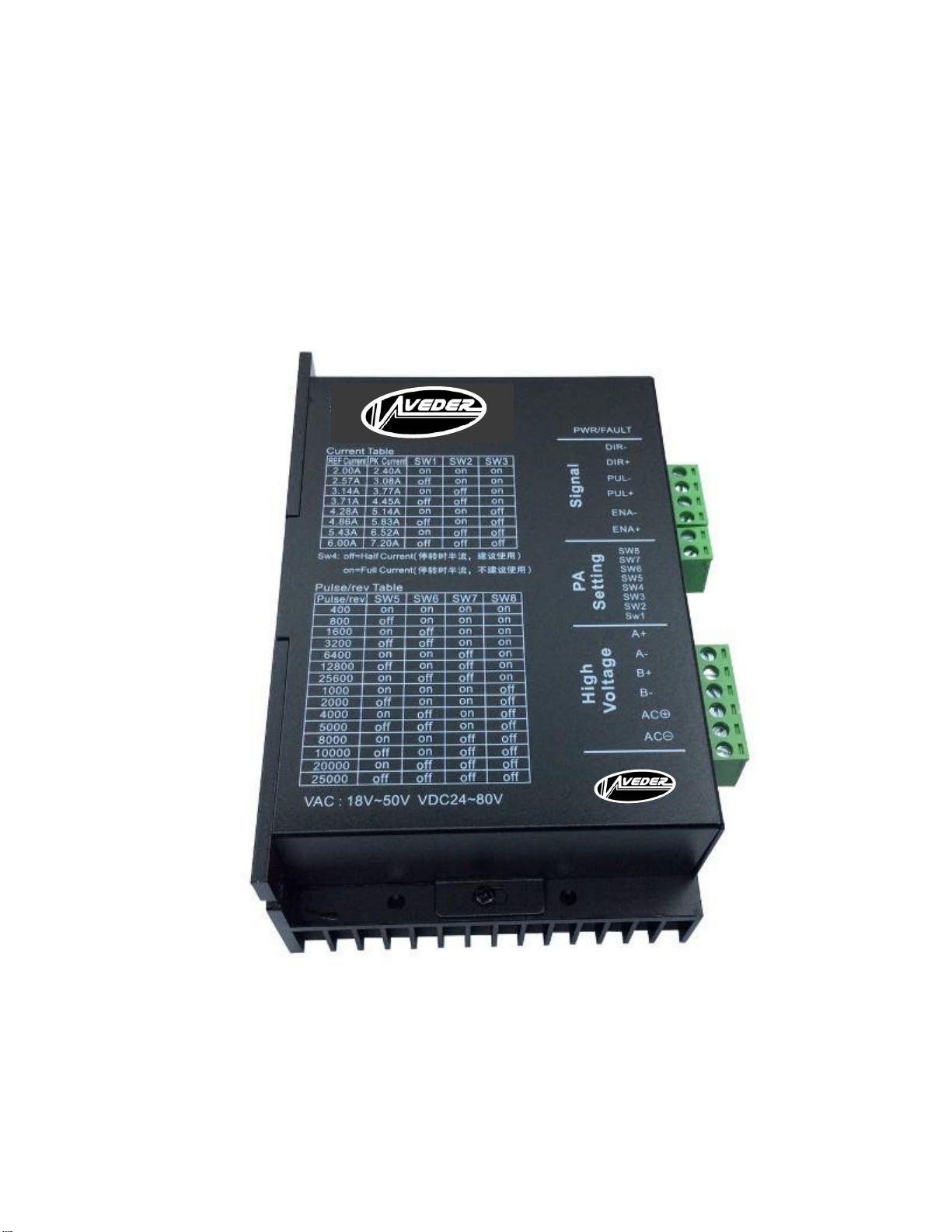
Electrical Specifications .......................................................................................................................................... 1
Operating Environment and other Specifications.....................................................................................................2
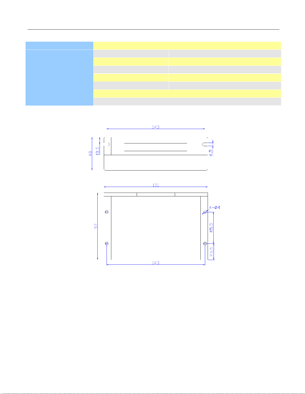
Mechanical Specifications........................................................................................................................................2
Elimination of Heat ................................................................................................................................................. 2
3. Pin Assignment and Description.................................................................................................................................. 3
Connector P1 Configurations................................................................................................................................... 3
Selecting Active Pulse Edge or Active Level and Control Signal Mode...................................................................3
Connector P2 Configurations................................................................................................................................... 4
4. Control Signal Connector (P1) Interface ......................................................................................................................4
5. Connecting the Motor..................................................................................................................................................4
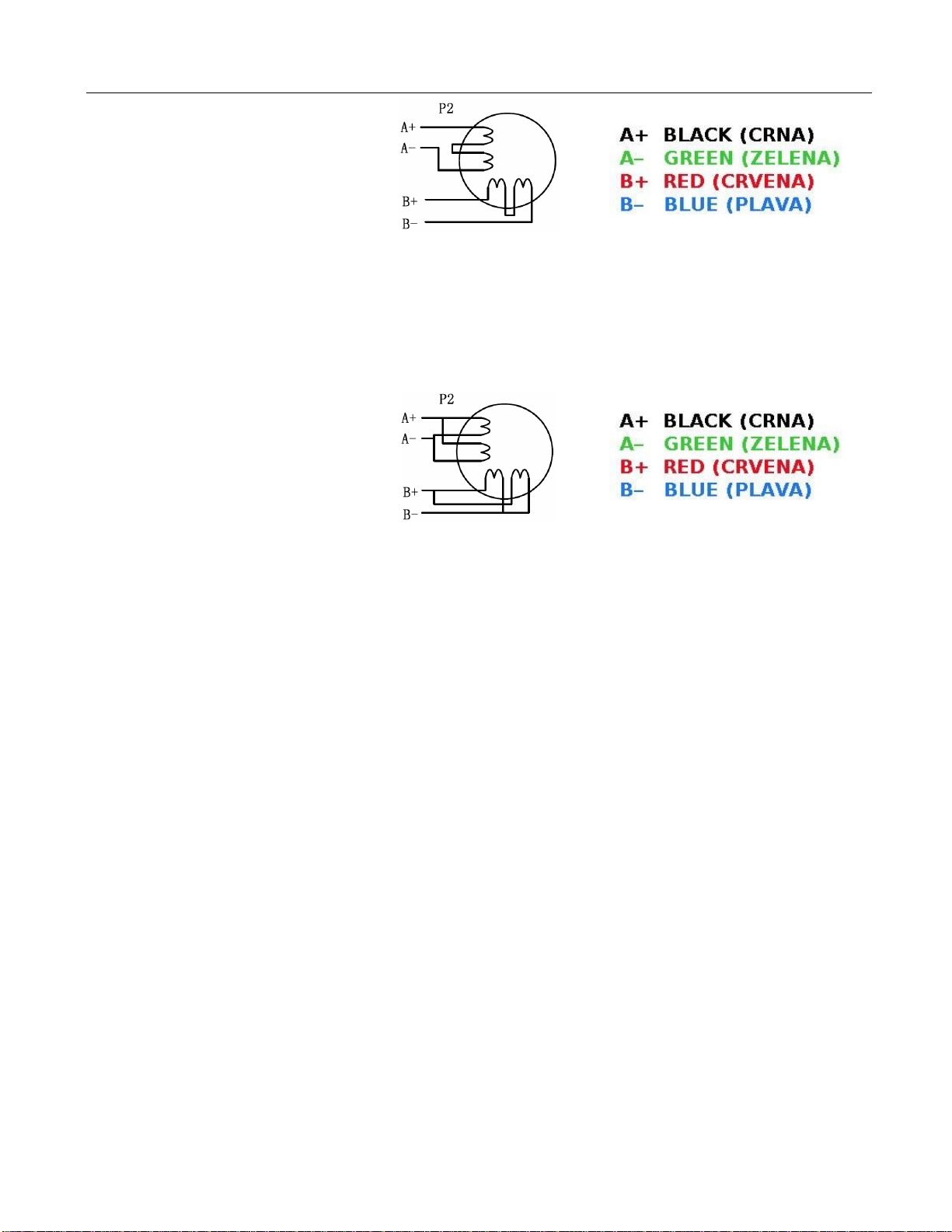
Connections to 4-lead Motors..................................................................................................................................4
Connections to 6-lead Motors..................................................................................................................................5
Half Coil Configurations ................................................................................................................................. 5
Full Coil Configurations...................................................................................................................................5
Connections to 8-lead Motors..................................................................................................................................5
Series Connections........................................................................................................................................... 5
Parallel Connections.........................................................................................................................................6
6. Power Supply Selection...............................................................................................................................................6
Regulated or Unregulated Power Supply................................................................................................................. 6
Multiple Drivers ...................................................................................................................................................... 6
Selecting Supply Voltage. ....................................................................................................................................... 7
7. Selecting Microstep Resolution and Driver Output Current........................................................................................ 7
Microstep Resolution Selection...............................................................................................................................7
Current Settings........................................................................................................................................................7
Dynamic Current Setting..................................................................................................................................8
Standstill Current Setting.................................................................................................................................8
28BAuto Tuning by SW4.........................................................................................................................................8
8. Wiring Notes................................................................................................................................................................ 9
9. Typical Connection...................................................................................................................................................... 9
10. Sequence Chart of Control Signals..........................................................................................................................10
11. Protection Functions.................................................................................................................................................10
12. Frequently Asked Questions.....................................................................................................................................11
Problem Symptoms and Possible Causes ...............................................................................................................11

1
1. Introduction, Features and Applications
Introduction
The DM860 is a fully digital stepper drive developed with advanced DSP control algorithm based on the latest motion
control technology. It has achieved a unique level of system smoothness, providing optimal torque and nulls mid-range
instability.
Compared with traditional analog drives, DM860 can drive a stepper motor at much lower noise,
lower heating, and smoother movement. Its unique features make DM860 an ideal choice for high requirement
applications.
Features
l Anti-Resonance provides optimal torque and nulls mid-range instability
l Multi-Stepping allows a low resolution step input to produce a higher microstep output, thus offers smoother
motor movement
l 16 selectable microstep resolutions including 400, 800, 1600, 3200, 6400, 12800, 25600, 51200, 1000, 2000, 4000,
l 5000, 8000, 10000, 20000, 40000
l Input voltage 24-80VDC
l 8 selectable peak current including 2.40A, 3.08A, 3.77A, 4.45A, 5.14A, 5.83A, 6.52A, 7.20A
l Pulse input frequency up to 200 KHz, TTL compatible and optically isolatedinput
l Automatic idle-current reduction
l Suitable for 2-phase and 4-phase motors
l Over-voltage, over-current protections
Applications
Suitable for a wide range of stepping motors, from NEMA size 17 to 42. It can be used in various kinds of machines,
such as X-Y tables, engraving machines, labeling machines, laser cutters, pick-place devices, and so on. Particularly
adapt to the applications desired with low noise, low heating, high speed and high precision.
2. Specifications
Electrical Specifications (Tj= 25 /77 )
Min Typical
DM860
Max Unit
Parameters
Output Current
Input Voltage
Logic Signal Current
Pulse input frequency
Pulse Width
Pulse Voltage
Isolation resistance
1.0 -
7.2 (Peak)
A
+24 +68
+80
VDC
7 10
16
mA
0 -
200
kHz
2.5 -
-
uS
- 5
-
VDC
500
MΩ

2
Operating Environment and other Specifications
Cooling
Natural Cooling or Forced cooling
Operating Environment
Storage Temperature
Weight
Environment
Avoid dust, oil fog and corrosive gases
Ambient Temperature
0℃-50℃
Humidity
40%RH -90%RH
Operating Temperature
70℃Max
Vibration
5.9m/s2Max
-20℃-65℃
Approx. 620g (21.7oz)
Mechanical Specifications (unit: mm [inch])
Figure 1: Mechanical specifications
*Recommend use side mounting for better heat dissipation
Elimination of Heat
l Driver’s reliable working temperature should be <70℃(158℉), and motor working temperature should be
<80℃(176℉);
l It is recommended to use automatic idle-current mode, namely current automatically reduce to 50% when motor
stops, so as to reduce driver heating and motorheating;
l It is recommended to mount the driver vertically to maximize heat sink area. Use forced cooling method to cool
the system if necessary.

3
3. Pin Assignment and Description
The DM860 has two connectors, connector P1 for control signals connections, and connector P2 for power and motor
connections. The following tables are brief descriptions of the two connectors. More detailed descriptions of the pins
and related issues are presented in section 4, 5, 9.
Connector P1 Configurations
h
o
Pin Function
Details
PUL+
Pulse signal: In single pulse (pulse/direction) mode, this input represents pulse signal, eac
rising or falling edge active; 4.5-5V
PUL-
DIR+
DIR signal: In single-pulse mode, this signal has low/high voltage levels, representing tw
directions of motor rotation;
DIR-
ENA+
Enable signal: This signal is used for enabling/disabling the driver. High level (NPN control
signal, PNP and differential control signals are on the contrary, namely low level for enabling.)
for enabling the driver and low level for disabling the driver. Usually left UNCONNECTED
(ENABLED).
ENA-

4
Connector P2 Configurations
Pin Function
VDC
GND
A+, A-
Details
Power supply, 24 ~ 80 VDC, Including voltage fluctuation and EMF voltage.
Power Ground.
Motor Phase A
B+, B-
Motor Phase B
4. Control Signal Connector (P1) Interface
The DM860 can accept differential and single-ended inputs (including open-collector and PNP output). The DM860
has 3 optically isolated logic inputs which are located on connector P1 to accept line driver control signals. These
inputs are isolated to minimize or eliminate electrical noises coupled onto the drive control signals. Recommenduse
line driver control signals to increase noise immunity of the driver in interference environments. In the following
figures, connections to open-collector and PNP signals are illustrated.
Figure 3: Connections to open-collector Figure 4: Connection to PNP signal (common-cathode)
signal (common-anode)
5. Connecting the Motor
The DM860 can drive any 2-pahse and 4-pahse hybrid stepping motors.
Connections to 4-lead Motors
4 lead motors are the least flexible but easiest to wire. Speed and torque will depend on winding inductance. In setting
the driver output current, multiply the specified phase current by 1.4 to determine the peak output current.
Figure 5: 4-lead Motor Connections
Controller
Drive
Controller
Drive

5
Connections to 6-lead Motors
Like 8 lead stepping motors, 6 lead motors have two configurations available for high speed or high torque operation.
The higher speed configuration, or half coil, is so described because it uses one half of the motor’s inductor windings.
The higher torque configuration, or full coil, uses the full windings of the phases.
Half Coil Configurations
As previously stated, the half coil configuration uses 50% of the motor phase windings. This gives lower inductance,
hence, lower torque output. Like the parallel connection of 8 lead motor, the torque output will be more stable at higher
speeds. This configuration is also referred to as half chopper. In setting the driver output current multiply the specified
per phase (or unipolar) current rating by 1.4 to determine the peak output current.
Figure 6: 6-lead motor half coil (higher speed) connections
Full Coil Configurations
The full coil configuration on a six lead motor should be used in applications where higher torque at lower speeds is
desired. This configuration is also referred to as full copper. In full coil mode, the motors should be run at only 70% of
their rated current to prevent over heating.
Figure 7: 6-lead motor full coil (higher torque) connections
Connections to 8-lead Motors
8 lead motors offer a high degree of flexibility to the system designer in that they may be connected in series or parallel,
thus satisfying a wide range of applications.
Series Connections
A series motor configuration would typically be used in applications where a higher torque at lower speeds is required.
Because this configuration has the most inductance, the performance will start to degrade at higher speeds. In series
mode, the motors should also be run at only 70% of their rated current to prevent over heating.

6
Figure 8: 8-lead motor series connections
Parallel Connections
An 8 lead motor in a parallel configuration offers a more stable, but lower torque at lower speeds. But because of the
lower inductance, there will be higher torque at higher speeds. Multiply the per phase (or unipolar) current rating by
1.96, or the bipolar current rating by 1.4, to determine the peak output current.
6. Power Supply Selection
Figure 9: 8-lead motor parallel connections
The DM860 can match medium and small size stepping motors (from NEMA frame size 17 to 34) made by many
motor manufactures around the world. To achieve good driving performances, it is important to select supply
voltage and output current properly. Generally speaking, supply voltage determines the high speed performance of the
motor, while output current determines the output torque of the driven motor (particularly at lower speed). Higher
supply voltage will allow higher motor speed to be achieved, at the price of more noise and heating. If the motion
speed requirement is low, it’s better to use lower supply voltage to decrease noise, heating and improvereliability.
Regulated or Unregulated Power Supply
Both regulated and unregulated power supplies can be used to supply the driver. However, unregulated power supplies
are preferred due to their ability to withstand current surge. If regulated power supplies (such as most switching
supplies.) are indeed used, it is important to have large current output rating to avoid problems like current clamp, for
example using 4A supply for 3A motor-driver operation. On the other hand, if unregulated supply is used, one may use
a power supply of lower current rating than that of motor (typically 50% -70% of motor current). The reason is that
the driver draws current from the power supply capacitor of the unregulated supply only during the ON duration of the
PWM cycle, but not during the OFF duration. Therefore, the average current withdrawn from power supply is
considerably less than motor current. For example, two 3A motors can be well supplied by one power supply of 4A
rating.
Multiple Drivers
It is recommended to have multiple drivers to share one power supply to reduce cost, if the supply has enough capacity.
To avoid cross interference, DO NOT daisy-chain the power supply input pins of the drivers. (Instead, please connect
them to power supply separately.)

7
Selecting Supply Voltage
The power MOSFETS inside the DM860 can actually operate within +24 ~ +110VDC, including power input
fluctuation and back EMF voltage generated by motor coils during motor shaft deceleration. Higher supply voltage can
increase motor torque at higher speeds, thus helpful for avoiding losing steps. However, higher voltage may cause
bigger motor vibration at lower speed, and it may also cause over-voltage protection or even driver damage.Therefore,
it is suggested to choose only sufficiently high supply voltage for intended applications, and it is suggested to use
power supplies with theoretical output voltage of +20 ~ +68VDC, leaving room for power fluctuation and back-EMF.
7. Selecting Microstep Resolution and Driver Output Current
This driver uses an 8-bit DIP switch to set microstep resolution, and motor operating current, as shown below:
Microstep Resolution Selection
Microstep resolution is set by SW5, 6, 7, 8 of the DIP switch as shown in the following table:
Microstep
2
Steps/rev.(for 1.8°motor) SW5
SW6
SW7
SW8
400
ON
ON
ON
ON
4
800
OFF
ON
ON
ON
8
1600
ON
OFF
ON
ON
16
3200
OFF
OFF
ON
ON
32
6400
ON
ON
OFF
ON
64
12800
OFF
ON
OFF
ON
128
25600
ON
OFF
OFF
ON
256
5
51200
1000
OFF
OFF
OFF
ON
ON
ON
ON
OFF
10
20
2000
4000
OFF
ON
ON
OFF
ON
OFF
ON
OFF
25
5000
OFF
OFF
ON
OFF
40
8000
ON
ON
OFF
OFF
50
10000
OFF
ON
OFF
OFF
100
20000
ON
OFF
OFF
OFF
200
40000
OFF
OFF
OFF
OFF
Current Settings
For a given motor, higher driver current will make the motor to output more torque, but at the same time causes more
heating in the motor and driver. Therefore, output current is generally set to be such that the motor will not overheat for
long time operation.

7
Since parallel and serial connections of motor coils will significantly change resulting inductance and resistance, it is
therefore important to set driver output current depending on motor phase current, motor leads and connection methods.
Phase current rating supplied by motor manufacturer is important in selecting driver current, however the selection also
depends on leads and connections.
The first three bits (SW1, 2, 3) of the DIP switch are used to set the dynamic current. Select a setting closest to your
motor’s required current.
Dynamic Current Setting
REF Current
2.00A
2.57A
Peak Current
2.40A
3.08A
SW1
SW2
SW3
ON
ON
ON
OFF
ON
ON
3.14A
3.77A
ON
OFF
ON
3.71A
4.28A
4.45A
5.14A
OFF
OFF
ON
ON
ON
OFF
4.86A
5.83A
6.52A
7.20A
OFF
ON
OFF
5.43A
6.00A
ON
OFF
OFF
OFF
OFF
OFF
Notes: Due to motor inductance, the actual current in the coil may be smaller than the dynamic current setting,
particularly under high speed condition.
Standstill Current Setting
SW4 is used for this purpose. OFF meaning that the standstill current is set to be half of the selected dynamic current,
and ON meaning that standstill current is set to be the same as the selected dynamic current.
The current automatically reduced to 50% of the selected dynamic current one second after the last pulse. Theoretically,
this will reduce motor heating to 36% (due to P=2I*R)of the original value. If the application needs a different
standstill current.
28B

8
8. Wiring Notes
l In order to improve anti-interference performance of the driver, it is recommended to use twisted pair shieldcable.
l To prevent noise incurred in PUL/DIR signal, pulse/direction signal wires and motor wires should not be tied up
together. It is better to separate them by at least 10 cm, otherwise the disturbing signals generated by motor will
easily disturb pulse direction signals, causing motor position error, system instability and other failures.
l If a power supply serves several drivers, separately connecting the drivers is recommended instead of daisy-
chaining.
l It is prohibited to pull and plug connector P2 while the driver is powered ON, because there is high current
flowing through motor coils (even when motor is at standstill). Pulling or plugging connector P2 with power on
will cause extremely high back-EMF voltage surge, which may damage the driver.
9. Typical Connection
A complete stepping system should include stepping motor, stepping driver, power supply and controller (pulse
generator). A typical connection is shown as figure 10.
Figure 10: Typical connection
Controller
DM860
VCC = 5V
270O
VCC
PUL+
Pulse
270O
Direction
ENA+
270O
ENA-
Enable
Motor
A-
B-
Recommended PowerSupply
24 ~ 68VDC
VDC
GND
PUL-

9
10. Sequence Chart of Control Signals
In order to avoid some fault operations and deviations, PUL, DIR and ENA should abide by some rules, shown as
following diagram:
Figure 11: Sequence chart of control signals
Remark:
a) t1: ENA must be ahead of DIR by at least
µ
5s. Usually, ENA+ and ENA- are NC (not connected). See
“Connector P1 Configurations” for more information.
b) t2: DIR must be ahead of PUL effective edge by 5µsto ensure correctdirection;
c) t3: Pulse width not less than 2.5µs;
d) t4: Low level width not less than 2.5µs.
11. Protection Functions
To improve reliability, the driver incorporates some built-in protections features.
Priority
Time(s) of
Blink
Sequence wave of red LED
Description
1st
1
2
Over-current protection activated when peak
current exceeds the limit.
Over-voltage protection activated when drive
working voltage is greater than 96VDC
2nd
When above protections are active, the motor shaft will be free or the red LED blinks. Reset the driver by repowering it
to make it function properly after removing above problems.

10
12. Frequently Asked Questions
In the event that your driver doesn’t operate properly, the first step is to identify whether the problem is electrical or
mechanical in nature. The next step is to isolate the system component that is causing the problem. As part of this
process you may have to disconnect the individual components that make up your system and verify that they operate
independently. It is important to document each step in the troubleshooting process. You may need this documentation
to refer back to at a later date, and these details will greatly assist our Technical Support staff in determining the
problem should you need assistance.
Many of the problems that affect motion control systems can be traced to electrical noise, controller software errors, or
mistake in wiring.
Problem Symptoms and Possible Causes
Symptoms
Motor is not rotating
Motor rotates in the wrong direction
Possible Problems
No power
Microstep resolution setting is wrong
DIP switch current setting is wrong
Fault condition exists
The driver is disabled
Motor phases may be connected in reverse
The driver in fault
Erratic motor motion
DIP switch current setting is wrong
Something wrong with motor coil
Control signal is too weak
Control signal is interfered
Wrong motor connection
Something wrong with motor coil
Current setting is too small, losing steps
Motor stalls during acceleration
Excessive motor and driver heating
Current setting is too small
Motor is undersized for the application
Acceleration is set too high
Power supply voltage too low
Inadequate heat sinking / cooling
Automatic current reduction function not being utilized
Current is set too high
This manual suits for next models
1
Table of contents
Popular DC Drive manuals by other brands

Rockwell Automation
Rockwell Automation Allen-Bradley PowerFlex 700 installation instructions

Danfoss
Danfoss ADAP-KOOL AKD 102 operating instructions

Danfoss
Danfoss VLT AQUA Drive FC 202 operating guide

Lenze
Lenze 9300 vector Information for the operator of the machine

WEG
WEG MVW01 user manual

Texas Instruments
Texas Instruments TLC5916 manual