Veeder-Root HydrX Reference guide
1
Troubleshooting Guide
HydrXTM Fuel Conditioning System
Quick Help - FCC Control
Section 1 - Introduction
This document focuses on maintenance alerts that occur with the HydrX System and what to do about them.
• Veeder-Root makes no representation or warranty about the information in this publication. A qualified professional is
required for service of the components addressed in this publication.
• The information in this publication cannot be used as a substitution for the knowledge and experience of a qualified
professional.
• The information contained in this publication is merely for the consideration of a qualified professional, which should make
their own determination of how to address any issues based on the situation.
• Veeder-Root shall not be liable for errors contained herein or for any type of damages in connection with the
furnishing, performance, or use of this publication.
• Veeder-Root reserves the right to change system options or features, or the information contained in this publication, at any
time without notice.
• This publication contains proprietary information which is protected by copyright. All rights reserved. No part of this
publication may be photocopied, reproduced, or translated to another language without the prior written consent of Veeder-
Root.
• Contact TLS Systems Technical Support for additional troubleshooting information at 800-323-1799.
Contractor Certification Requirements
Veeder-Root requires the following minimum training certifications for contractors who will install and program the equipment
discussed in this manual:
Service Technician Certification (Previously known as Level 2/3): Contractors holding valid Technician Certifications are
approved to perform installation checkout, startup, programming and operations training, system tests, troubleshooting and
servicing for all Veeder-Root Series Tank Monitoring Systems, including Line Leak Detection. This certification includes TLS-3xx
and TLS-4xx certification training.
In-Station Diagnostics (ISD-PMC) Technician Certification: ISD PMC Contractors holding a valid ISD/PMC Certification
are approved to perform (ISD/PMC) installation checkout, startup, programming, and operations training. This training also
includes troubleshooting and service techniques for the Veeder-Root In-Station Diagnostics system. A current Veeder-Root
Technician Certification is a prerequisite for the ISD/PMC course.
All service personal on site must comply with all recommended safety practices identified by OSHA and your employer.
Review and comply with all the safety warnings in the manuals listed in this document above and any other Federal, State or
Local requirements.
Warranty Registrations may only be submitted by selected Distributors.
Safety Warnings
FAILURE TO COMPLY WITH THE FOLLOWING WARNINGS AND SAFETY PRECAUTIONS COULD RESULT IN
SERIOUS INJURY OR DEATH, AND/OR CAUSE DAMAGE TO PROPERTY, AND THE ENVIRONMENT.
Due to the presence of high voltages, pressurized fuel connections and hazardous work area
dangers, only certified service technicians should attempt repairs to the HydrX System
components and/or wiring connections.
Related Manuals
577014-466 HydrX™ Fuel Conditioning System Setup & Operation Manual - FCC Control
577014-446 HydrX™ Fuel Conditioning System Installation Manual
Manual No: 577014-472 l Revision: D

2
Troubleshooting Guide
HydrX Quick Help - ATG Control Section 2 - HydrX System Alarm Notifications
Section 2 - HydrX System Alarm Notifications
HydrX System alarms appear in the TLS-4xx display Status Bar and turn on the console beeper. Touch the display Status Bar
to silence the alarm (see Figure 1).
Figure 1. Display Status Bar
On the FCC display, alarms will turn the Status Bar red and the alarm will continue to scroll horizontally across the red bar until
the alarm is resolved.
Figure 2. FCC Home Screen
Always check the FCC display to identify alarms as the TLS-4xx does not differentiate between all HydrX System alarms.
Section 3 - Upgrading HydrX System Software
To avoid electric shock do not touch any wiring terminals inside the FCC while performing this
procedure.
1. If you have a FCC upgrade thumb drive with the software upgrade already on it, go to Step 3.
2. If you have downloaded the FCC software onto a PC, insert a thumb drive into your PC and copy the HGDATA01 directory
from your PC location to the root directory of the thumb drive (typically drive labeled D).
The USB is formatted as FAT32, so your PC operating system must support the FAT32 file system to copy
this file. Newer versions of MAC OS support this, but you should make certain if you are copying from a
MAC. Specify that it is OK to overwrite the contents.
3. Open the door of the FCC and with the power to the FCC On, plug the upgrade thumb drive into the FCC USB2 port on
the rear of the FCC Display.
Figure 3. FCC USB2 Port - Rear of FCC Display

3
Troubleshooting Guide
HydrX Quick Help - ATG Control Section 4 - FCC Clock Setup
4. When the Confirmation screen displays, touch the Download Proj. button to install the software upgrade.
Figure 4. FCC Conformation Screen
5. The FCC will go through a series of steps loading the project contents into its memory. Wait for the Confirmation screen to
return then touch Cancel to return to the Home screen.
6. The new code and user interfaces are downloaded to the FCC. Remove the thumb drive and close and secure the FCC
cover.
Section 4 - FCC Clock Setup
To set the FCC internal clock on initial startup follow the steps below.
1. Touch the upper left corner of the FCC display Status Bar and press it until the Maintenance screen appears:
Figure 5. Accessing Maintenance Screen from FCC Home Screen
2. When the Maintenance screen appears touch the System Mode button to open the System Mode top page:
Figure 6. Accessing System Mode
3. On the System Mode Top Page, touch the Main Menu button:
Figure 7. System Mode Top Page Screen
4
Troubleshooting Guide
HydrX Quick Help - ATG Control Section 4 - FCC Clock Setup
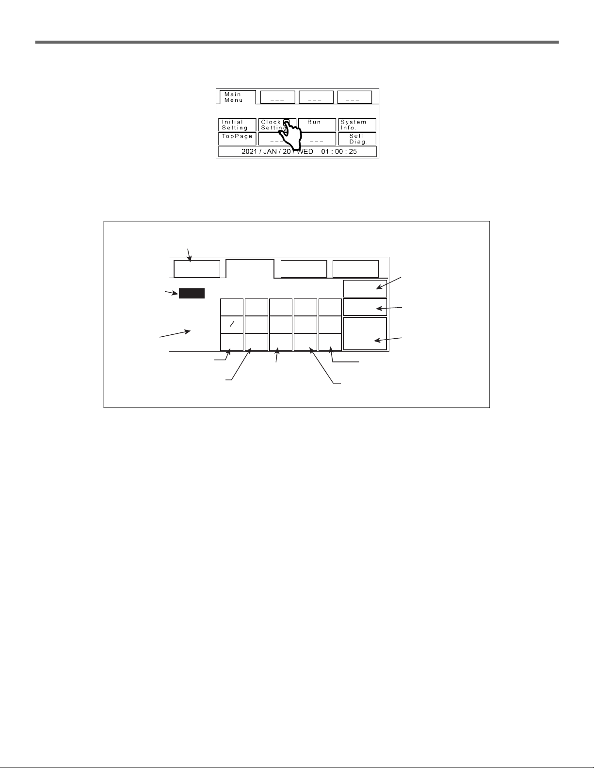
4. On the Main Menu page touch the Clock Setting button open the Clock Set page:
Figure 8. Accessing Clock Setting Screen
5. On the Clock Set screen, observe the button functions shown below to reset the date and time. Touch the number buttons
to enter date/time.
Figure 9. FCC Clock Set Screen
6. After saving the date and time, touch the Main Menu button to return to the System Mode Top Page Screen (see
Figure 7, then touch the Run button on that page return to the FCC Home screen.
YYYY / MM / DD HH : MM : SS
/ 01 / 20 01 : 09 : 37
9AC
SAVE
Main
Menu
Clock
Set – – –
< – – – – >
– – –
8765
43210
CLR CAN ENT
2020 2021
Highlighted
area is
active
Touch to return
to Main Menu
Touch to accept
scratch pad
entry/overwrite
active area value
Touch to scroll
to next entry
Touch to scroll
to previous entry
Active area
scratch pad
Touch to clear
scratch pad
Message
window
Touch to erase all
entries before
touching Save
Touch to save new
clock setting
Touch to cancel
previous entry
5
Troubleshooting Guide
HydrX Quick Help - ATG Control Section 5 - HydrX System Alarm Troubleshooting
Section 5 - HydrX System Alarm Troubleshooting
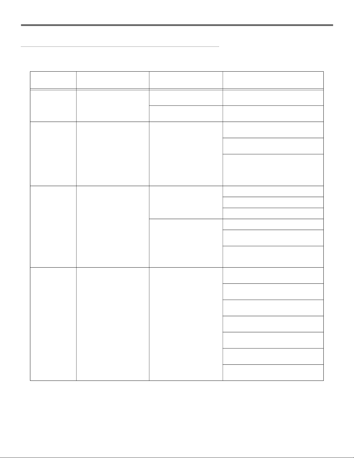
HYDRX SYSTEM MAINTENANCE ALERTS
FCC Display
Message
TLS-450PLUS
Status Message Cause Action
Status: Drain User programmed custom
alarm, i.e., "HydrX Service"
HydrX water collection tank
full Drain tank (refer to Manual 577014-474).
HydrX "Tank Volume" set to 0 Set proper Tank Volume, Refer to page 5
of this manual.
Status: Filter User programmed custom
alarm, i.e., "HydrX Service"
HydrX filter at end of life
(EOL)
Run ‘Fill Cycle’, if alarm persists, move to
next action step.
Replace filters (refer to Manual 577014-
473).
Filter EOL% settings (page 7) can be low-
ered to continue operation; however, a
system operating with filters below 5% life
will quickly produce subsequent filter
alarms due to filter loading characteristics.
Status: Comm User programmed custom
alarm, i.e., "HydrX Service"
Persistent communications
errors between HydrX and
ATG
Check serial cable connection.
Check ATG serial settings.
Test serial cable continuity.
HydrX Mag Probe or
Pressure Sensor out
Check ATG for probe or sensor out alarm.
Check wiring on HydrX probe or pressure
sensor.
Replace HydrX Mag Probe or Pressure
Sensor as outlined in manual 577014-469
or 577014-470 respectively.
Status: Pressure
Fault Pressure Fault Insufficient Pressure
Check that pressure for New Filter Cycle
is at least15 psi.
Ensure current filter life% is above EOL%
set by user.
Run ‘Fill Cycle’. After running ‘Fill Cycle’
check ‘Filter Life’ on FCC controller.
Verify line HydrX is assigned to is enabled
and not in alarm.
If P or PO inlet is negative, verify inlet and
outlet valves are wired correctly.
Check STP pressure at HydrX adapter
port.
Follow Pressure fault advanced trouble-
shooting guide on page 10 of this manual.
6
Troubleshooting Guide
HydrX Quick Help - ATG Control Section 5 - HydrX System Alarm Troubleshooting
GENERAL TROUBLESHOOTING
1. Ensure that the STP pump circuit breaker is turned On.
2. Ensure that the handle on STP Adapter ball valve is pointing in the correct direction of flow. You can verify this by the
curved arrow on the handle. The arrow should be pointing to the pump port and the port that the HydrX hose is connected
to.
3. Ensure that there are no alarms on the ATG that could possibly prevent the pump from turning on (i.e. DPLLD Gross Line
Fail or Pump Shutdown Alarm).
4. Look in the Diesel STP Sump for any signs of visible leaks around the filter caps and hose connections and ensure that
flaretite seals were connected on each hose connections.
5. Check the HydrX Filter Performance screen on the FCC to ensure that the filters are not clogged. If there is a large
discrepancy between Initial and Last Pressure, the HydrX filters could be clogged.
6. Close the STP Adapter ball valve and remove both filters. Make sure that the plastic wrapping was removed from the
outside of each filter and then ensure that both filters are seated properly in the bottom of each filter compartment. The
opening on the bottom of each filter is keyed to the bottom of each filter compartment. You may need to rotate the filter to
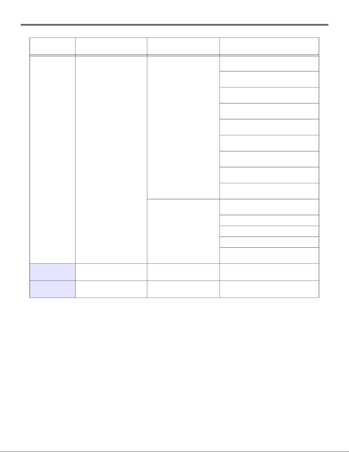
Status: Vacuum
Fault Vacuum Fault
Insufficient Vacuum
For New Filter Cycle check that vacuum is
> -1.25 psi.
For New Filter Cycle check that vacuum is
< -10 psi.
For Filter Cycle check that vacuum is
> -1.25 psi.
For Filter Cycle check that vacuum is
< -13 psi.
Run ‘Fill Cycle’. After running ‘Fill Cycle’
check ‘Filter Life’ on FCC controller.
Verify line to which HydrX is assigned is
enabled and not in alarm.
If P or PO outlet pressure is positive, verify
inlet and outlet valves are wired correctly.
Verify that HydrX siphon cartridge screen
is not clogged (ref. manual 577014-478).
Check STP pressure at HydrX adapter
port.
Vacuum Leak
Run ‘Fill Cycle’. After running Fill Cycle,
vacuum level should hold below -0.75 psi.
Check drain valve seated.
Check for loose hose connections.
Check filter cover o-rings.
Follow advanced vacuum fault trouble-
shooting guide on page 10 of this manual.
HydrX Probe Out
(TLS-450PLUS) FC Mag probe inoperative Replace FC mag probe (refer to Manual
577014-469).
HydrX Sensor Out
(TLS-450PLUS)
FC Pressure sensor inopera-
tive Replace FC pressure sensor (refer to Man-
ual 577014-470).
FCC Display
Message
TLS-450PLUS
Status Message Cause Action

7
Troubleshooting Guide
HydrX Quick Help - ATG Control Section 5 - HydrX System Alarm Troubleshooting
get it to align with the bottom of the filter compartment. Once aligned, press the filter down to seat it fully (reference manual
577014-473 for correct filter installation).
7. Turn off the submersible pump power, close STP adapter ball valve and then remove, inspect, and clean or replace the
siphon cartridge on the top of the HydrX manifold (refer to Manual 577014-478 for Siphon Cartridge servicing instructions)
8. Inspect the drain valve to ensure it is not stuck open.
TROUBLESHOOTING TIPS
Accessing FCC Manual Control
1. Go to the Self Diag. screen on the FCC as follows:
a. Touch and hold the upper left corner of the FCC display status bar (about 3 seconds) until the Maintenance screen
appears (see Figure 5).
b. When the Maintenance screen appears touch the System Mode button (see Figure 6).
c. On the System Mode Top Page screen, touch the Main Menu button (see Figure 7.
d. On the Main Menu screen touch the Self Diag button (see Figure 10)
Figure 10. Main Menu Screen
e. On the Self Diag screen touch the I/O button (see Figure 11)
Figure 11. Self Diag. Screen
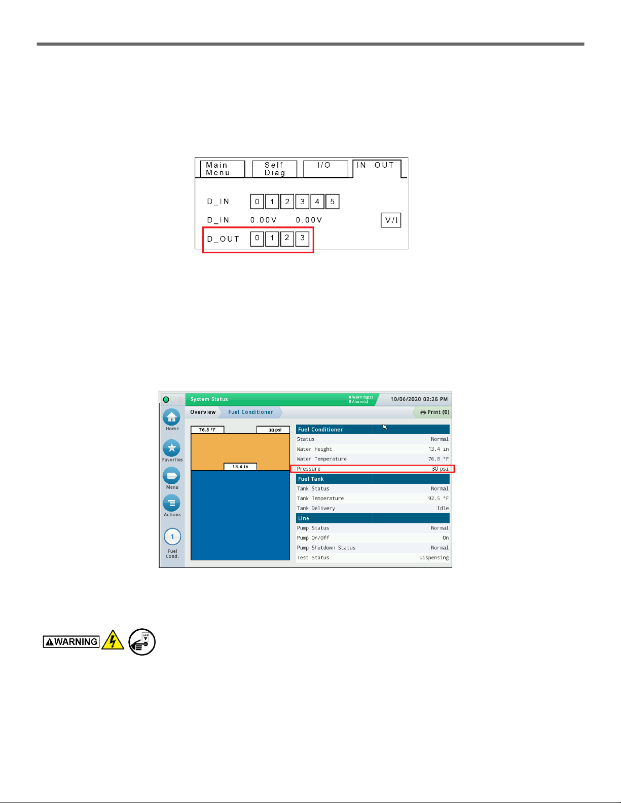
f. On the I/O screen touch the IN OUT button (see Figure 12)
Figure 12. I/O Screen
8
Troubleshooting Guide
HydrX Quick Help - ATG Control Section 5 - HydrX System Alarm Troubleshooting
g. On the IN OUT screen (see Figure 13) in the D_OUT number buttons, touch:
- 0-to energize the inlet valve
- 1-to energize the outlet valve
- 2-to energize the pump hook
- 3-To test the FCC alarm
Figure 13. IN OUT Screen
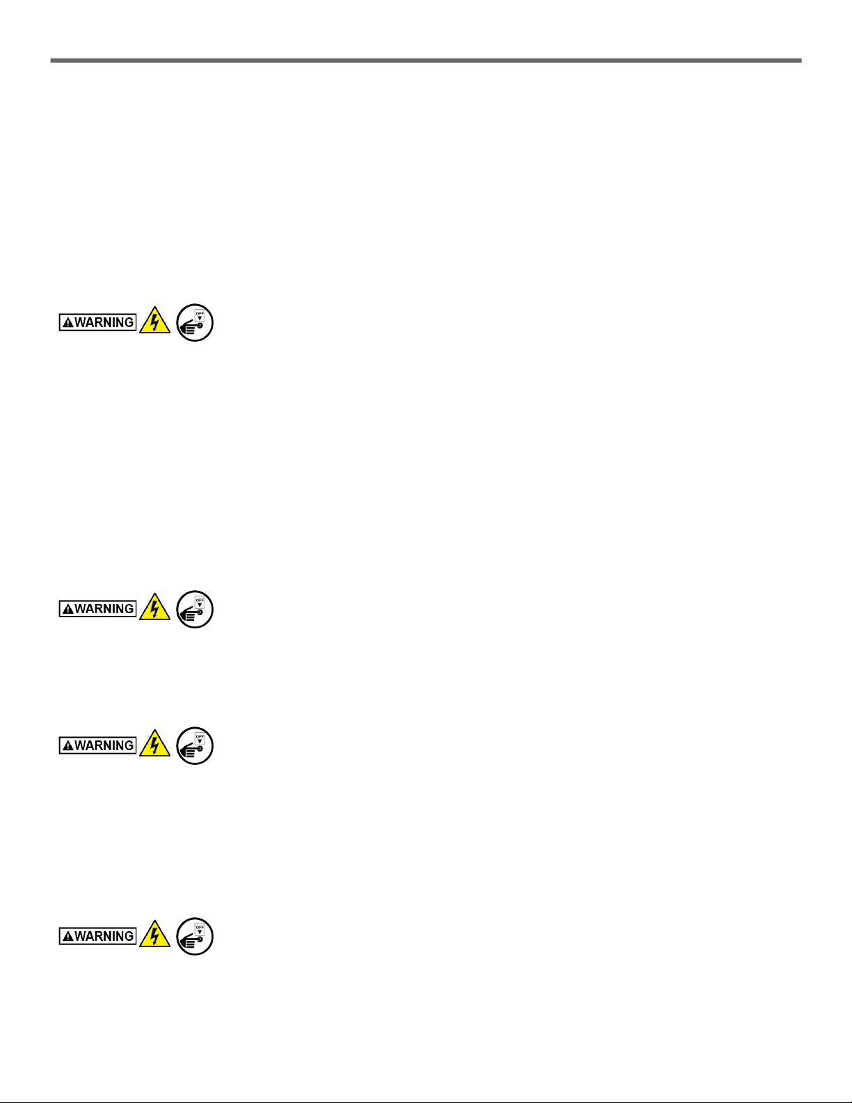
Pressure Fault Actions
The HydrX system requires a minimum15 psi reading on its pressure sensor for system startup with new filters. If pressure is
lower than 15 psi the following steps can be taken.
1. Enter the FCC Self Diag. screen (see Figure 11) by following the steps in “Accessing FCC Manual Control” above.
2. At the D_OUT buttons on the IN OUT screen (see Figure 13), touch 0 and 2. If the pressure is still below 15 psi, de-
energize the devices and verify general troubleshooting steps have been followed before continuing.
Figure 14. TLS-4xx HydrX Overview Screen
3. If adequate pressure cannot be generated, the STP Adapter ball valve and check valve must be inspected:
Tag, lockout power to the STP.
- Remove and inspect the STP Adapter ball and check valve for any debris that may be restricting flow.
- Verify that the ball valve is opening fully.
- Re-install STP Adapter assembly and repeat Step 2 to check pressure.
9
Troubleshooting Guide
HydrX Quick Help - ATG Control Section 5 - HydrX System Alarm Troubleshooting
Vacuum Fault Actions
The HydrX system requires a minimum vacuum level of -1.25 psi on its pressure sensor for startup with new filters. If at least
-1.25 psi cannot be generated the following steps can be taken.
1. Enter the FCC Self Diag. screen by following the steps in “Accessing FCC Manual Control” above.
2. Turn on the STP and Outlet Valve (Touch 0 and 1 on the IN OUT screen). Observe the Pressure reading in the Fuel
Conditioner tab on the TLS-4xx HydrX Overview>Fuel Conditioner screen (see Figure 14).
3. If the vacuum level cannot reach at least -1.25 psi, de-energize the devices and verify general troubleshooting steps have
been followed before continuing.
4. Excessive Vacuum. If at system startup, the HydrX pressure sensor is reading more than -10 psi vacuum, an alarm will be
generated. This is generally due to a blockage in or damage to the WID.
Tag, lockout power to the STP.
- Close the STP Adapter ball valve.
- Remove the (3) 1/4" bolts securing the WID to the guide tube and raise the WID so the tubing is visible. Once damage
such as kinked tubing or excessive debris is corrected, repeat step 1 after power is restored to check vacuum levels.
5. Vacuum Loss during Idle Periods. 30 minutes after each HydrX cycle, a leak check is performed on the fuel conditioner
housing. Under normal circumstances the housing will hold a vacuum of around -1.5 psi during idle periods. If after 30
minutes from the last HydrX cycle the vacuum in the housing is between -0.75 and 0 psi, an alarm will be generated. This
indicates that there is a small leak in the system. At system startup verify that the general troubleshooting steps have been
followed.
a. If no leaks are visually present and the system cannot hold vacuum during idle periods the following steps can be
followed
- Run a Fill or New Filter cycle. Setting ‘Fill Time’ to 3 minutes allows for quicker troubleshooting.
- After running a complete Fill or New Filter Cycle, the clear tubing on the WID should be filled with fuel. Any presence
of bubbles or air cavities indicate a leak in the WID. This can be checked at the end of the cycle.
Tag, lockout power to the STP.
- Close the STP Adapter ball valve. Visually inspect tubing by removing the (3) 1/4" bolts securing the WID to the
guide tube and raising the WID so the tubing is visible. If any significant air leaks are present, contact technical
support for further action.
b. Uneven or obstructed valve sealing surfaces can also cause slow leaks in the system that will cause it to fail the idle
leak check.
Tag, lockout power to the STP.
- Close the STP Adapter ball valve and ensure that FC Outlet Valve (round body) was not accidentally loosened during
installation. Loosen valve coil nut and snug valve body by turning the knurled valve body clockwise.
- If the valve body was loose, tighten the coil nut and re-enable the system by unlocking the STP breaker, opening the
pump adapter ball valve and running a fill or new filter cycle. If the outlet valve body was tight, continue with the
following steps.
c. Debris accumulated in the valve seats can also cause slow vacuum loss. This generally applies to systems that have
been in service for an extended period of time, however, this can be an issue with highly contaminated retrofit sites or
construction debris in new installations.
Tag, lockout power to the STP.
- Close the STP Adapter ball valve.
- Remove the Siphon Cartridge from the HydrX manifold and inspect the screen. If heavy debris is present on this
screen and siphon cavity, the Inlet Valve sealing surfaces may also contain similar debris.

10
Troubleshooting Guide
HydrX Quick Help - ATG Control Section 5 - HydrX System Alarm Troubleshooting
- The Inlet Valve cavity can be checked for debris by loosening the Inlet Valve (square body) coil nut, and removing the
conduit and (4) Allen head mounting screws.
- All surfaces of the valve body, operator and cavity should be cleaned and free of heavy debris. The valve cavity can be
cleaned easily by flushing fluid through the Siphon Cartridge cavity and out the Inlet Valve cavity.
- Re-assemble the valve, restore power to the STP, open the STP Adapter ball valve and run a Fill or New Filter cycle.
- If all of the previous steps have been taken contact Veeder-Root Technical Support for further instructions.
Comm Fault
1. The comm parameters for the FCC are 9600, odd, 1, 7. Ensure that the communication parameters set on the TLS-4xx
comm port are set to the correct serial port and match the FCC parameters.
2. Ensure the serial connectors are inserted in the serial ports on the FCC and TLS-4xx all the way and are screwed into
place.
3. If the serial connectors are inserted properly and the comm parameters are programmed properly on the TLS-4xx serial
port, replace the Ethernet cable that connects both serial ports. Ensure it is a standard Ethernet cable and not a crossover
cable.
©Veeder-Root 2023 All rights reserved.
Other manuals for HydrX
4
Table of contents
Other Veeder-Root Industrial Equipment manuals


