Elgo LIMAX S-RMS-H User manual

Montageanleitung
Magnetband Montageset mit Banderkennung mit Spannfedern für Highrise Aufzüge
(Original)
Mounting instructions
Magnetic tape installation kit with tape detection and tension spring for high rise elevators
(Translation of the original mounting instructions)
Instructions de montage
Kit d'installation de la bande magnétique avec détection de Bande avec ressort de traction pour ascenseurs de
grande hauteur
(Traduction du manuel de montage original)
LIMAX S-RMS-H
D-103932 / Rev. 3 / 07.08.2019
799000971

- 2 -
1Inhalt / Content / Table des matières
1Inhalt / Content / Table des matières ...............................................2
2Set Inhalt / Kit Content / Contenu du Kit...........................................2
3Zu diesem Dokument / About this Document / A propos de ce document 3
4Montageablauf / Installation Procedure / Procédure d'installation .6
2Set Inhalt / Kit Content / Contenu du Kit
English
Crossbeam for position switch (1x)
Crossbeam (2x)
Tape fixture for position switch (1x)
Tension spring (3x) or (2x)
Cable ties (2x)
Rail clips including screws and nuts (10x)
Position switch including screws and cable gland (1x)
Original description of position switch
Deutsch
Querträger für Positionsschalter (1x)
Querträger (2x)
Bandhalter für Positionsschalter (1x)
Zugfeder (3x) oder (2x)
Kabelbinder (2x)
Schienenklemmen inkl. Schrauben und Muttern (10x)
Positionsschalter inkl. Schrauben und Kabelverschraubung
(1x)
Originalbeschreibung Positionsschalter
Français
Traverse pour Commut. de position (1x)
Traverse (2x)
Attache de bande pour interrupteur (1x)
Ressort de traction (3x) ou (2x)
Serres-câble (2x)
Agrafes des rails incluant les vis et écrous (10x)
Commut. de position avec vis et presse étoupe (1x)
Mode d'emploi original de l’interrupteur (allemand/an-
glais)
Document- No.:
D-103932 / Rev. 3
Document- Name:
LIMAX-S-RMS-H-000-MI-DEF
Änderungen vorbehalten / Subject to change / Sous réserve de
modifications –© 2019, ELGO Batscale AG
ELGO Batscale AG
F ö h r e n w e g 2 0 , F L - 9 4 9 6 B a l z e r s
Fon.:+423 (0) 380 02 22, Fax.:+423 (0) 380 02 24
Internet: www.elgo.li, Mail: info@elgo.li
Measuring | Positioning | Control

- 3 -
3Zu diesem Dokument / About this Document / A propos de ce document
3.1 Funktion / Function / Fonction
D
Die vorliegende Montageanleitung liefert die erforderlichen Informationen für die Montage, die Inbetriebnahme, den sicheren
Betrieb sowie die Demontage des LIMAX S-RMS-H. Die Montageanleitung ist stets in einem leserlichen Zustand und zugänglich
aufzubewahren.
E
These mounting instructions provide all the information you need for mounting, commissioning, the safe operation and disas-
sembly of the LIMAX S-RMS-H. The mounting instructions must be available in a legible condition and complete version in the
vicinity of the device.
F
Le présent mode d'emploi contient les informations nécessaires au montage, au raccordement, à la mise en service, à un fonc-
tionnement sûr ainsi que des remarques importantes concernant le démontage du LIMAX S-RMS-H. Il est important de conserver
le mode d'emploi (en condition lisible) près de l'appareil, accessible à tout moment comme partie intégrante du produit.
3.2 Zielgruppe: autorisiertes Fachpersonal / Target group: Authorized Qualified Personnel
/ Groupe cible: personnel spécialisé autorisé
D
Sämtliche in dieser Montageanleitung beschriebenen Handhabungen dürfen nur durch ausgebildetes und vom Anlagenbetreiber
autorisiertes Fachpersonal durchgeführt werden.
Installieren und nehmen Sie das Gerät nur dann in Betrieb, wenn Sie die Montageanleitung gelesen und verstanden haben. Ma-
chen Sie sich mit den geltenden Vorschriften über Arbeitssicherheit und Unfallverhütung vertraut.
Auswahl und Einbau der Geräte sowie ihre steuerungstechnische Einbindung sind an eine qualifizierte Kenntnis der einschlägigen
Gesetze und normativen Anforderungen durch den Maschinenhersteller geknüpft.
E
All operations described in these mounting instructions must be carried out only by trained specialist personnel, authorized by the
plant operator.
Please make sure that you have read and understood these mounting instructions and that you know all applicable prescriptions
regarding occupational safety and accident prevention prior to installation and commissioning.
Selection and installation of the devices as well as their embedding into the controlling system require qualified knowledge of the
applicable laws and normative requirements on the part of the machine manufacturer.
F
Uniquement du personnel qualifié, spécialisé et habilité par l'exploitant de l'installation est autorisé à effectuer les instructions
décrites dans ce mode d'emploi.
Il est important de lire et de comprendre le mode d'emploi avant l'installation et la mise en service du composant. Vous devez
également connaître les prescriptions en vigueur concernant la sécurité du travail et la prévention des accidents.
Pour le choix et le montage des composants ainsi que leur intégration dans le circuit de commande, le constructeur de machines
doit observer les exigences des directives harmonisées et des règlements en vigueur.
3.3 Verwendete Symbolik / Explanation of the Symbols used / Symboles utilisés
D
Vorsicht:
Bei Nichtbeachten dieses Warnhinweises können Störungen oder Fehlfunktionen die Folge sein.
Warnung:
Bei Nichtbeachten dieses Warnhinweises können ein Personenschaden und/oder ein Schaden an der Maschine
die Folge sein.
E
Caution:
Failure to comply with this warning notice could lead to interferences or malfunctions.
Warning:
Failure to comply with this warning notice could lead to physical injury and/or damage to the machine.
F
Attention:
Le non-respect de cette recommandation peut entraîner des pannes ou des défauts de fonctionnement.
Avertissement:
Le non-respect de cette instruction peut entraîner des blessures physiques et/ou des dommages à la machine.

- 4 -
3.4 Bestimmungsmäßiger Gebrauch / Appropriate Use / Définition de l'application
D
Das hier beschriebene Produkt wurde entwickelt, um als Teil einer Gesamtanlage oder Maschine sicherheitsgerichtete Funktionen
zu übernehmen. Es liegt im Verantwortungsbereich des Herstellers einer Anlage oder Maschine, die korrekte Gesamtfunktion
sicherzustellen.
Das LIMAX S-RMS-H darf nur für durch den Hersteller zugelassene Anwendungen eingesetzt werden.
E
The product described in these mounting instructions was developed to execute safety-related functions as a part of an entire
assembly or machine. It is the responsibility of the manufacturer of a machine or installation to ensure the proper functioning of
the system.
The LIMAX S-RMS-H must be exclusively used for the applications authorized by the manufacturer.
F
Le produit décrit dans ce mode d'emploi a été développé pour réaliser des fonctions relatives à la sécurité comme partie inté-
grante d'une machine ou d'une installation. Le constructeur de la machine ou de l'installation est responsable du fonctionnement
correct de l'ensemble.
Le LIMAX S-RMS-H ne doit être utilisé que pour les applications autorisées par le fabricant.
3.5 Allgemeine Sicherheitshinweise / General Safety Instructions / Consignes de sécurité
générales
D
Die Sicherheitshinweise der Montageanleitung sowie landesspezifische Installations-, Sicherheits- und Unfallverhütungsvorschrif-
ten sind zu beachten.
Alle Angaben ohne Gewähr. Änderungen, die dem technischen Fortschritt dienen, vorbehalten.
E
The user must observe the safety instructions in these mounting instructions, the country-specific installation standards as well as
all applicable safety regulations and accident prevention rules.
The information contained in these mounting instructions manual is provided without liability. Subject to technical modifications.
F
Les consignes de sécurité de ce mode d'emploi, les standards d'installation spécifiques au pays concerné ainsi que les disposi-
tions de sécurité et les règles de prévention d'accidents sont à observer.
Les caractéristiques et recommandations figurant dans ce document sont uniquement données à titre d’information et sans enga-
gement contractuel de notre part. Sous réserve de modifications techniques.
3.6 Haftungsausschluss / Exclusion of Liability / Clause de non-responsabilité
D
Für Schäden und Betriebsstörungen, die durch Montagefehler oder Nichtbeachtung dieser Montageanleitung entstehen, wird
keine Haftung übernommen. Für Schäden, die aus der Verwendung von nicht durch den Hersteller freigegebenen Ersatz- oder
Zubehörteilen resultieren, ist jede weitere Haftung des Herstellers ausgeschlossen.
Jegliche eigenmächtige Reparaturen, Umbauten und Veränderungen sind aus Sicherheitsgründen nicht gestattet und schließen
eine Haftung des Herstellers für daraus resultierende Schäden aus.
E
We shall accept no liability for damage and malfunctions resulting from incorrect mounting or failure to comply with these
mounting instructions. The manufacturer shall accept no liability for damage resulting from the use of unauthorized spare parts
or accessories.
For safety reasons, invasive work on the device as well as arbitrary repairs, conversions and modifications to the device are
strictly forbidden; the manufacturer shall accept no liability for damage resulting from such invasive work, arbitrary repairs, con-
versions and/or modifications to the device.
F
Nous déclinons les dommages et défaillances issus d'un montage erroné ou de la non-observation des instructions de ce mode
d'emploi. Nous déclinons également la responsabilité pour les dommages résultant de l’utilisation d'accessoires ou de pièces de
rechange non autorisés par le fabricant.
Pour des raisons de sécurité, il est strictement interdit de transformer ou modifier un dispositif de sécurité de sa propre initiative.
Le fabricant ne peut être tenu responsable pour les dommages y découlant.
- 5 -
FIG 1
FIG 2
FIG 3
FIG 4
FIG 5
FIG 6

- 6 -
FIG 7
FIG 8
4Montageablauf / Installation Procedure / Procédure d'installation
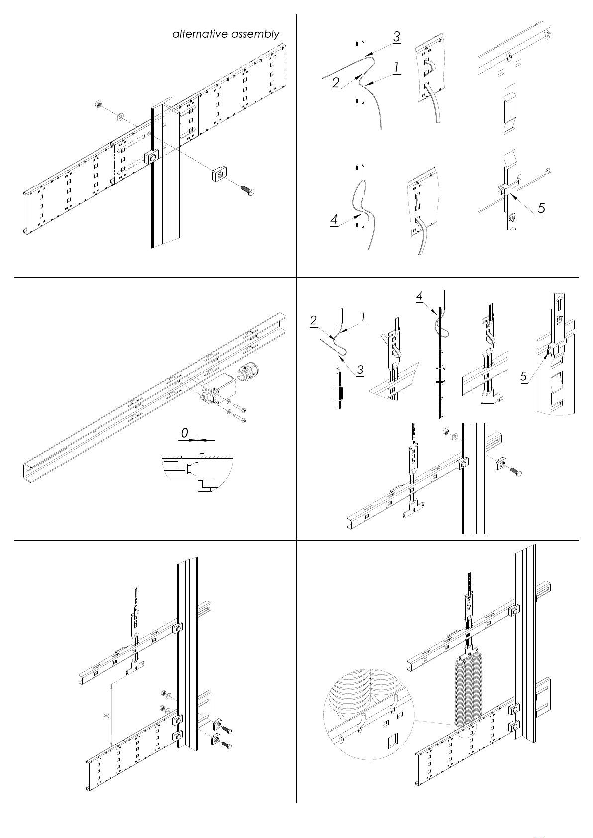
4.1 FIG 1
D
Befestigen Sie einen Querträger im Schachtkopf an die Führungsschiene. Stellen Sie einen festen Anzug der Schrauben sicher
min. 45 Nm, so dass sich der Träger auch unter Last nicht verschiebt.
Die Montage kann alternativ auch rechts der Aufzugsschiene stattfinden.
E
Install one crossbeam in the shaft head by using the rail clips. Make sure that the clips screws are well tightened min. 45 Nm, so
that the crossbeam does not move.
As an alternative, it can also be mounted to the right of the elevator rail.
F
Installez une traverse sur le haut du rail de guidage en utilisant les clips de fixation et visseries fournis. Assurez-vous que la tra-
verse soit bien fixée min. 45 Nm et qu'elle ne bouge pas.
Le montage s’effectue soit à gauche soit à droite du rail (montage alternatif).
4.2 FIG 2
D
Fädeln Sie das Band in den Querträger wie im Bild gezeigt. Nützen sie den Schlitz, welcher sich für die Platzverhältnisse in Ihrer
spezifischen Installation am besten eignet. Eine Position möglichst nahe an der Führungsschiene ist zu bevorzugen. Achten Sie auf
die Orientierung des Bandes. Die Magnetseite muss später zum Sensorkörper zeigen. Das Prinzip funktioniert wie ein selbsthem-
mender Gürtel. Lassen Sie mindestens 20 cm Band überstehen und drücken Sie das Band im Bandhalter flach. Ein Knick im obe-
ren Bogen ist gewünscht. Sichern Sie zum Schluss das Band mit einem Kabelbinder am unteren Ende des Bandhalters.
E
Thread the tape through the crossbeam and back down, as shown. Use any of the slots provided depending on your specific
space situation in the installation. A position as close to the guide rail as possible is advantageous. Mind the orientation of the
tape –the magnet side must face the sensor body later on. Basically, the fixture works like a self-locking belt. Leave at least
20 cm tape at the spare end. Press the loops flat in the clamp. There should be a break in the upper loop. In the end, secure the
tape with a cable tie at the bottom of the clamp.
F
Enfiler la bande dans la traverse comme sur l'image. Utilisez l'emplacement souhaité en fonction de la position de la bande sou-
haitée dans la cage d'ascenseur. Un emplacement le plus près possible du rail de guidage et d’avantage. Attention au sens de la
bande - la face magnétique doit être située du côté du corps du capteur. Le principe est un auto serrage de la bande. Laissez au
moins 20 cm de bande dépasser l'extrémité de l'attache. Tirez sur la bande pour replier la boucle et sécuriser la en installant un
serre câble.

- 7 -
4.1 FIG 3
D
Der Querträger für den Sicherheits-Positionsschalter sollte zur späteren Installation vormontiert werden. Die Kabelverschraubung
an den Positionsschalter montieren. Den Positionsschalter in Richtung der Blechkante bündig ausrichten (Detail). Anschließend die
Schrauben mit 3 Nm festziehen. Im Montageset sind gewindefurchende Schrauben nach DIN 7500 enthalten.
Vor der Montage Positionsschalter bereits verkabeln. Bei der Montage und dem Anschluss des Sicherheitspositionsschalters ist die
beiliegende Montageanleitung des Herstellers zu beachten.
E
The crossbeam for the safety position switch should be pre-mounted for the installation later. Mount the cable screw connections
to the position switch. Align the position switch with the edge of the metal (detail). Then fasten the screws with 3 Nm. The assem-
bly set includes thread-forming screws according to DIN 7500. Wire the position switch already before mounting. When mount-
ing and connecting the safety position switch, observe the enclosed operation manual from the manufacturer.
F
La traverse pour l‘interrupteur de sécurité doit être prémontée pour une installation ultérieure.
Montez les presse-étoupes sur l’interrupteur, aligner l’interrupteur en direction du bord de la traverse (détail). Serrez les vis avec
3 Nm. Brancher l’interrupteur avant le montage. Le kit de montage comprend des vis autoformeuses selon DIN 7500.
Pour le montage et le branchement de commut. de position, conformez-vous aux instructions du fabricant.
4.2 FIG 4
D
Nach dem Verlegen des Bandes im Aufzugschacht, den Bandhalter für Positionsschalter von unten in den Querträger einfahren.
Danach das Band am unteren Ende einfädeln. Lassen sie mindestens 20 cm Band überstehen und drücken Sie das Band im
Bandhalter flach. Ein Knick im unteren Bogen ist gewünscht. Sichern Sie zum Schluss das Band mit einem Kabelbinder am oberen
Ende des Bandhalters. Der Querträger kann nun provisorisch an der Führungsschiene fixiert werden.
E
After the tape has been installed in the shaft, bring in the tape fixture for the position switch from below into the crossbeam. After
that mount the tape at the lower end. Leave at least 20 cm at the spare end and press the loop flat in the clamp. There should be
a break in the lower loop. The end, secure the tape with a cable tie at the top of the clamp. The crossbeam can now be tempo-
rarily fixed to the guide rail.
F
Après avoir déroulé la bande dans la cage d'ascenseur, enfiler l'attache pour commut. de position, d'en bas, dans la Traverse.
Enfiler la Bande dans l'attache et Laissez au moins 20 cm de bande dépasser l'extrémité de l'attache. Presser la band à plat et
sécuriser la en installant un serre câble. La traverse peut maintenant être fixée temporairement au rail de guidage
4.3 FIG 5
D
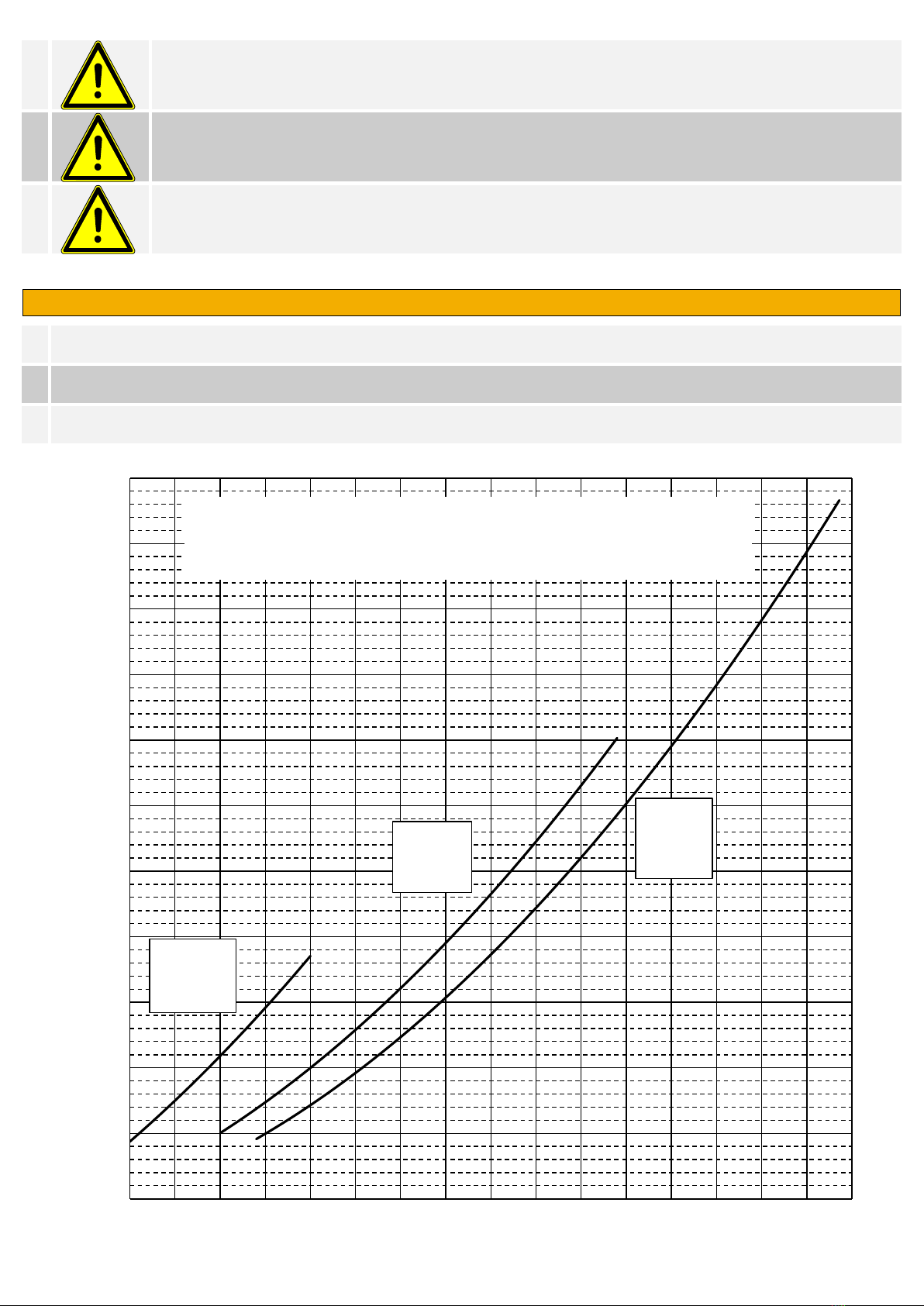
Montieren Sie den unteren Querträger im Abstand X (X gemäss Diagramm FIG 9). Stellen Sie einen festen Anzug der Schrauben
sicher min. 45 Nm, so dass sich der Träger auch unter Last nicht verschiebt.
E
Mount the below crossbeam in distance X (X according diagram FIG 9). Make sure that the clips screws are well tightened min.
45 Nm, so that the crossbeam does not move.
F
Monter la traverse inférieure à la distance X (X selon schéma FIG 9). Assurez-vous que la traverse soit bien fixée min. 45 Nm et
qu'elle ne bouge pas.
4.4 FIG 6
D
Montieren Sie die Zugfedern (3x) oder (2x) am Bandhalter. Achten Sie auf den korrekten Sitz der Feder in der Bohrung (Detail)
VORSICHT: Feder nicht über 500mm strecken
E
Mount the tension spring (3x) or (2x) to the tape fixture. Make sure the spring is correctly placed in the drill hole (detail)
Caution: Don’t stretch spring over 500mm
F
Montez le ressort de traction (3x) ou (2x) à l'attache. Veillez que le ressort soit correctement placé dans son trou (détail)
Attention : Ne pas étirez le ressort plus de 500mm
4.5 FIG 7
D
Der Querträger für den Sicherheits-Positionsschalter wird so positioniert, dass nur eine Markierung an der Bandklammer nach
oben und eine nach unten sichtbar ist (siehe Detail A). Der Querträger muss im 90° Winkel zur Aufzugsschiene montiert werden.
Wenn der Querträger für den Sicherheits-Positionsschalter richtig positioniert worden ist werden die Schrauben mit 20 Nm festge-
zogen. Dabei ist darauf zu achten, dass der Querträger nicht verrutscht.
E
The crossbeam for the safety position switch is positioned in such a way that only one marking on the tape clamp can be seen
towards both the top and the bottom (see detail A). The crossbeam must be mounted in a 90° angle to the elevator rail.
When the crossbeam has been correctly positioned, the screws are fastened with 20 Nm while making sure that the crossbeam is
not moved by accident.
F
La traverse de l’interrupteur de sécurité doit être placée de façon à ce que les marques de l’attache de bande soient visibles au-
dessus et au-dessous de la traverse (détail A) La traverse doit être montée avec un angle de 90° par rapport au rail.
Une fois la traverse bien positionnée, serrez les vis avec 20 Nm et veillez qu'elle ne bouge pas.
- 8 -
D
Warnung:
Durch fehlerhafte Positionierung des Querträgers kann die Funktion des Sicherheits-Positionsschalters beeinträch-
tigt werden.
E
Warning:
An incorrect position of the crossbeam can compromise the functionality of the safety position switch.
F
Avertissement:
Une mauvaise position de la traverse peut porter atteinte aux fonctions de l’interrupteur de sécurité
4.6 FIG 8
D
Zuletzt wird der Sicherheits-Positionschalter scharf gestellt. Dafür wird der Betätiger mit einem Schraubenzieher herausgezogen.
Dabei ist zu beachten, dass die Gummimanschette am Betätiger nicht beschädigt wird. Hiermit ist die Montage abgeschlossen.
E
Finally, the safety position switch is activated. To do this, the actuator is pulled out with a screw driver. Take care not to damage
the rubber sleeve on the actuator. This is the end of the installation.
F
En fin activer l’interrupteur de sécurité. Pour cela tiré le poussoir avec un tournevis, en faisant attention de ne pas endommager
la coupelle caoutchouc de protection du poussoir. Le montage est ainsi terminé.
200
300
400
500
600
700
800
900
1000
1100
1200
1300
050 100 150 200 250 300 350 400 450 500 550 600 650 700 750 800
X - Spanndistanz / Span distance / Distance de Tension [mm]
Bandlänge / tape lenght / Longeur de Bande [m]
Spanndistanz in Abhängigkeit der Bandlänge
Span distance in dependence of the tape lenght
Distance de Tension en dépendance de la longueur de Bande
1 Feder
1 Spring
1 Ressort
2 Federn
2 Spring
2 Ressort
3 Federn
3 Spring
3 Ressort
FIG 9
Other Elgo Industrial Equipment manuals


