Veeder-Root 847490-104 User manual

-~
ARTISAN
®
~I
TECHNOLOGY
GROUP
Your definitive source
for
quality
pre-owned
equipment.
Artisan Technology
Group
Full-service,
independent
repair
center
with
experienced
engineers
and
technicians
on staff.
We
buy
your
excess,
underutilized,
and
idle
equipment
along
with
credit
for
buybacks
and
trade-ins
.
Custom
engineering
so
your
equipment
works
exactly as
you
specify.
•
Critical
and
expedited
services
•
Leasing
/
Rentals/
Demos
• In
stock/
Ready-to-ship
•
!TAR-certified
secure
asset
solutions
Expert
team
ITrust
guarantee
I
100%
satisfaction
All
tr
ademarks,
br
a
nd
names, a
nd
br
a
nd
s a
pp
earing here
in
are
th
e property of
th
e
ir
r
es
pecti
ve
ow
ner
s.
Find the Veeder-Root 330749-001 at our website: Click HERE

Manual No: 576013-632 ●Revision: C
Installation Guide
Probe/Thermistor Interface Module

Notice
Veeder-Root makes no warranty of any kind with regard to this publication, including, but not limited to, the implied
warranties of merchantability and fitness for a particular purpose.
Veeder-Root shall not be liable for errors contained herein or for incidental or consequential damages in connection
with the furnishing, performance, or use of this publication.
Veeder-Root reserves the right to change system options or features, or the information contained in this publication.
This publication contains proprietary information which is protected by copyright. All rights reserved. No part of this
publication may be photocopied, reproduced, or translated to another language without the prior written consent of
Veeder-Root.
DAMAGE CLAIMS
1. Thoroughly examine all components and units as soon as they are received. If damaged, write a complete and
detailed description of the damage on the face of the freight bill. The carrier's agent must verify the inspection
and sign the description.
2. Immediately notify the delivering carrier of damage or loss. This notification may be given either in person or
by telephone. Written confirmation must be mailed within 48 hours. Railroads and motor carriers are reluctant
to make adjustments for damaged merchandise unless inspected and reported promptly.
3. Risk of loss, or damage to merchandise remains with the buyer. It is the buyer's responsibility to file a claim with
the carrier involved.
RETURN SHIPPING
For the parts return procedure, please follow the appropriate instructions in the "General Returned Goods Policy" and
"Parts Return" pages in the "Policies and Literature" section of the Veeder-Root North American Environmental
Products price list.
Veeder-Root 2003. All rights reserved.

Table of Contents
i
Introduction .......................................................................................................1
Related Manuals ...............................................................................................1
Contractor Certification Requirements ..........................................................1
Safety Precautions ...........................................................................................1
Module Positions and Labeling .......................................................................2
Figure 1 - Console Interface Module Bays ...................................................................2
Circuit Directory ................................................................................................3
Figure 2 - Modular Console System Circuit Directory ..................................................3
Installing Probe/Thermistor Interface Module - I.S. Bay ...............................4
Figure 3 - Probe/Thermistor Interface Module Wiring ..................................................4

Table of Contents
ii

Probe/Thermistor Interface Module Installation Guide Introduction
1
Introduction
This manual contains instructions for installing the Veeder-Root Probe/Thermistor Interface Module (P/N 847490-
104) in TLS-350/ProMax/EMC Consoles.
This manual assumes field wiring has been run from the Mag Probe and/or Thermistor to the console following
instructions in the appropriate console’s site prep manual.
Related Manuals
576013-879 TLS-3XX/ProMax/EMC Consoles Site Prep Manual (Mag Probe)
576013-873 VLLD Site Prep and Installation Manual (Thermistor)
576013-623 TLS-3XX Series Consoles System Setup Manual
Contractor Certification Requirements
Veeder-Root requires the following minimum training certifications for contractors who will install and setup the
equipment discussed in this manual:
Level 1 Contractors holding valid Level 1 Certification are approved to perform wiring and conduit routing,
equipment mounting, probe and sensor installation, tank and line preparation, and line leak detector installation.
Level 2/3 Contractors holding valid Level 2 or 3 Certifications are approved to perform installation checkout,
startup, programming and operations training, troubleshooting and servicing for all Veeder-Root Tank Monitoring
Systems, including Line Leak Detection and associated accessories.
Warranty Registrations may only be submitted by selected Distributors.
Safety Precautions
The following safety symbols may be used throughout this manual to alert you to important safety hazards and
precautions
EXPLOSIVE
Fuels and their vapors are extremely explo-
sive if ignited.
FLAMMABLE
Fuels and their vapors are extremely flammable.
TURN POWER OFF
Live power to a device creates a potential
shock hazard. Turn Off power to the device
and associated accessories when servicing
the unit.
READ ALL RELATED MANUALS
Knowledge of all related procedures before you
begin work is important. Read and understand all
manuals thoroughly. If you do not understand a
procedure, ask someone who does.
OFF

Probe/Thermistor Interface Module Installation Guide Module Positions and Labeling
2
Module Positions and Labeling
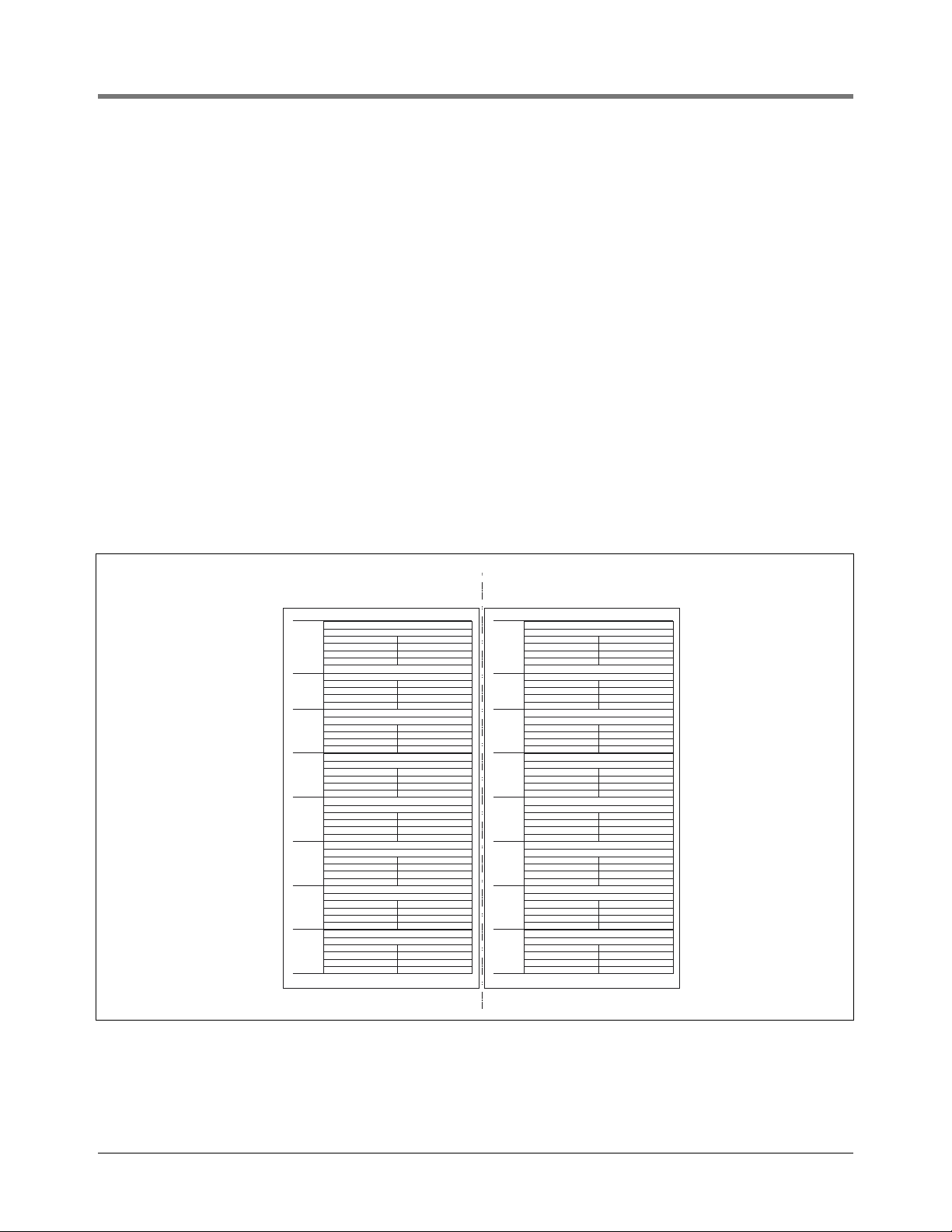
1. Modular consoles have three bays in which interface modules can be installed; Comm bay (left door), Power bay,
and Intrinsically Safe (I.S.) bay (right door). The Probe/Thermistor Interface Module is installed in the I.S. bay.
Figure 1. Console Interface Module Bays
In all cases, the position of all modules, their respective connectors, and the devices wired to the connectors
must be recorded to prevent improper replacement during installation or service. A circuit directory for Pow-
er and I.S. bay Interface Modules is adhered to the back of the right-hand door for this purpose.
During programming, module positions and the devices wired to each module are identified and stored in memo-
ry. If a connector is removed and reinstalled on a different module after programming, or if an entire module with
its connector is removed and reinstalled in a different module slot, the system will not properly recognize the data
being received.
2. If a system contains multiple modules of a single type (i.e., two Probe/Thermistor Interface Modules), they may be
swapped between their respective slot locations, however, the connectors must remain with their original
locations, not with the original modules.
WARNING
The equipment is used in location where lethal voltages and explosive vapors or flammable fuels
may be present.
Care must be taken when installing, servicing or replacing parts in the system or serious injury or
death from explosion, fire or shock may occur.
For this system:
1. Comply with the latest National Electric Code, federal, state, and local codes, and any other
applicable safety codes. In addition, take necessary precautions during installation, service,
and repair to prevent personal injury, property loss and equipment damage.
2. Refer servicing to trained and qualified personnel only.
3. Substitution of components may impair intrinsic safety.
4. Be sure AC power to the console is “OFF” before opening the console panel covers, plugging
in the module, and connecting probe and thermistor wires. Do not short any voltage across
any barrier terminal including sensors or probes.
OFF
console\350rjmods.eps
Intrinsically
Safe Bay
Permissible
Modules
(Limit 8
per console)
Power
Bay
Permissible
Modules
(Limit 8
per console)
1
2
3
4
5
6
7
8
9
10
11
12
13
14
15
16
12 34
Power Bay
Slot Numbers
Power Bay
Slot Numbers
I.S. Bay
Slot Numbers
Comm Bay
Slot Numbers
Comm Cage*
*See Serial Comm Installation Guide
for permissible modules.

Probe/Thermistor Interface Module Installation Guide Module Positions and Labeling
3
3. Once a device has been wired to certain terminals on a connector and the system has been programmed, the wires
from that device may not be relocated to other terminals without reprogramming the system.
Grounding Probe and Sensor Shields
Probe and sensor cable shields are grounded at the console only. Do not ground the shield in the field junction box.
CIRCUIT DIRECTORY
A circuit directory is adhered to the inside of the right-hand door. It should be filled out as the module’s connectors
are being wired.
The following information should be recorded for each module installed:
• Module Type: record what type of module has been installed in the slot, e.g., Probe/Thermistor Interface Module.
• Position Record: record the physical location and/or type of device wired to each terminal of the module connector
in the slot, e.g., Tank 1.
In the example directory shown in Figure 2, slot 4 contains a Probe/Thermistor Interface Module. Position 1 on the
connector receives the + and – wires from the probe in Tank 1, position 2 from the probe in Tank 2, etc. Since this
system has five tanks, a second Probe/Thermistor Interface Module is installed in slot 5 and its connector position 1
receives the wires from the probe in Tank 5.
Positions on each module are numbered and each connector terminal is identified with the acceptable input. There
are eight positions for each slot even though some modules accept fewer devices.
Figure 2. Modular Console System Circuit Directory
MODULE TYPE:
POSITION RECORD:
1
2
3
4
5
6
7
8
MODULE TYPE:
POSITION RECORD:
1
2
3
4
5
6
7
8
MODULE TYPE:
POSITION RECORD:
1
2
3
4
5
6
7
8
MODULE TYPE:
POSITION RECORD:
1
2
3
4
5
6
7
8
MODULE TYPE:
POSITION RECORD:
1
2
3
4
5
6
7
8
MODULE TYPE:
POSITION RECORD:
1
2
3
4
5
6
7
8
MODULE TYPE:
POSITION RECORD:
1
2
3
4
5
6
7
8
8
7
6
5
4
3
2
MODULE TYPE: VAPOR
POSITION RECORD:
1
2
3
4
5
6
7
8
1WELL #1
WELL #2
WELL #3
TANK 1 - INT
TANK 1 - SUMP
TANK 2 - INT
TANK 2 - SUMP
TANK 3 - INT
TANK 3 - SUMP
TANK 4 - INT
TANK 4 - SUMP
INTERSTITIAL
INTERSTITIAL
TANK 5 - INT
TANK 5 - SUMP
PROBE
TANK 1
TANK 2
TANK 3
TANK 4
PROBE
TANK 5
MODULE TYPE:
POSITION RECORD:
1
2
3
4
5
6
7
8
MODULE TYPE:
POSITION RECORD:
1
2
3
4
5
6
7
8
MODULE TYPE:
POSITION RECORD:
1
2
3
4
5
6
7
8
MODULE TYPE:
POSITION RECORD:
1
2
3
4
5
6
7
8
MODULE TYPE:
POSITION RECORD:
1
2
3
4
5
6
7
8
MODULE TYPE:
POSITION RECORD:
1
2
3
4
5
6
7
8
MODULE TYPE:
POSITION RECORD:
1
2
3
4
5
6
7
8
16
15
14
13
12
11
10
MODULE TYPE:
POSITION RECORD:
1
2
3
4
5
6
7
8
9LINE LEAK INP.
OVERFILL ALM OUT
METER 1
METER 2
METER 3
MDIM
I/O COMBO
Power Bay Slots Intrinsically Safe (IS) Bay Slots
consoles\moduldir.eps

Probe/Thermistor Interface Module Installation Guide Installing Probe/Thermistor Interface Module - I.S. Bay
4
Installing Probe/Thermistor Interface Module - I.S. Bay
Figure 3. Probe/Thermistor Interface Module Wiring
1. Turn Off power to the console. Open the right-hand door of the console. If you are replacing an existing Probe/
Thermistor Interface module, tag the probe wires with their positions, as you remove them from the old module.
Remove the old module.
If you are adding a new module, remove the blank plate from one of the unused I.S. slots.
2. Hold the new module with its snap-in fasteners positioned in the lower right and left corners and carefully slide
the module into its I.S. bay slot until its connector engages with the connector on the board.
3. Press down on the snap-in fasteners to secure the module. BE SURE ALL UNUSED SLOTS are covered with blank
snap-in plates.
4. Connectors are supplied with each module. They provide screw terminations for up to four Mag probes and up to
four Thermistors.
5. If replacing an old module, reconnect the tagged wires in exactly the same connector position on the new module
as they were in on the old module.
If adding a new module, connect two marked or color-coded wires from each Mag Probe (or Thermistor) to the
appropriate terminals on the module as shown in Figure 3. See the table below about device polarity.
6. Ground the shields of each probe wiring pair to one of the console’s ground terminals.
7. Reapply power to the console.
8. Refer to the TLS-3XX Setup Manual to program the Probe/Thermistor Interface Module.
Device Wires Observe Polarity
Mag Probe (up to 4) 2 Yes
Ground temperature thermistor - When using
volumetric line leak detection (VLLD), only
one ground temperature thermistor is needed
per site and the thermistor must be wired to
thermistor position number 1 (positions 2 - 4
are not used).
2No
PROBE /
THERMISTOR
MAXIMUM PROBE
OUTPUT RATINGS:
13 VDC
0.2 AMP
PROBE / THERMISTOR INTERFACE MODULE
1234 1234
PROBE THERMISTOR
consoles\ptimw.eps
Console
+
Probe
#1
+
Probe
#4
Thermistor
#1
Up to 4
Probes
+ + + +
Only 1 Thermistor needed per site
and it must be wired into position #1
Not Used
Attach Cable Shields to Ground
Lug Closest to Conduit Entry
Rigid Conduit
(enters Console
through an I.S. Bay
knockout)
OFF


Headquarters
125 Powder Forest Drive
Simsbury, CT 06070-7684
Tel: (860) 651-2700
Fax: (860) 651-2719
Email: marketing@veeder.com
Australia
Level 1 441 South Road
Moorabbin 3189 Victoria
Tel: +61 3 9556 5435
Fax: +61 3 9556 5482
Email: rxdupuy@veeder-australia.com
Brazil
Rua ado Benatti, 92
Sao Paulo - SP 05037-904
Tel: +55 (0) 11 3611 2155
Fax: +55 (0) 11 3611 1982
Email: clopez@veeder.com
Canada
Eastern Canada
Tel: (519) 925-9899
Western Canada
Tel: (604) 576-4469
Email: marketing@veeder.com
China
Room 2202, Scitech Tower
No. 22 Jian Guomen
Wai DaJie
Beijing 100004
Tel: +86 10 6512 8081
Fax: +86 10 6522 0887
Email: lu ying@veeder.com
England
Hydrex House, Garden Road
Richmond, Surrey TW9 4NR
Tel: +44 (0) 20 8392 1355
Fax: +44 (0) 20 8878 6642
Email: sales@veeder.co.uk
France
94-106 Rue Blaise Pascal
93600 Aulnay Sous Bois
Tel: +33 (0) 1 4879 5599
Fax: +33 (0) 1 4868 3900
Email: sales@veeder.co.uk
Germany
Uhlandstrabe 49
78554 Aldingen
Tel: +49 (0) 7424 1400
Fax: +49 (0) 7424 1410
Email: sales@veeder.co.uk
Mexico
Sagitario #4529-3
Col. La Calma C.P. 45070
Zapopan, Jalisco
Tel: (523) 632 3482
Fax: (523) 133 3219
Email: jmartinez@veeder.com
Poland
01-517 Warszawa ul. Mickiewicza 18/12
Tel/Fax: +48 (0) 22 839 08 47
Email: sales@veeder.co.uk
Veeder-Root has sales offices around the world to serve you.
Singapore
246 MacPherson Road
#08-01 Betime Building
348578
Tel: +65 (0) 6745 9265
Fax: +65 (0) 6745 1791
Email: francis yap@veeder.com

Artisan
Technology
Group
is
an independent supplier
of
quality pre-owned equipment
Gold-standard
solutions
Extend the life
of
your
critical industrial,
commercial, and military systems
with
our
superior service and support.
We
buy
equipment
Planning to
upgrade
your current
equipment? Have surplus equipment taking
up shelf space? We'll give it a
new
home.
Learn
more!
Visit us at artisantg.com for more info
on price quotes, drivers, technical
specifications, manuals, and documentation.
Artisan Scientific
Corporation
dba
Artisan
Technology
Group
is
not
an affiliate,
representative,
or
authorized
distributor
for
any
manufacturer
listed herein.
We're here to make your life easier.
How
can
we
help you today?
(217)
352-9330
Isales@artisantg.com Iartisantg.com
Table of contents
Popular Recording Equipment manuals by other brands

i4Technology
i4Technology BugHunter DAudio bda-2 Ultrasonic user manual

Alesis
Alesis IO|2 quick start guide

CHD Elektroservis
CHD Elektroservis Savvy Service manual

Studio Technologies
Studio Technologies 42A user guide

WOT Technologies
WOT Technologies TD1220RDR Service manual

PIRATE MIDI
PIRATE MIDI CLICK manual