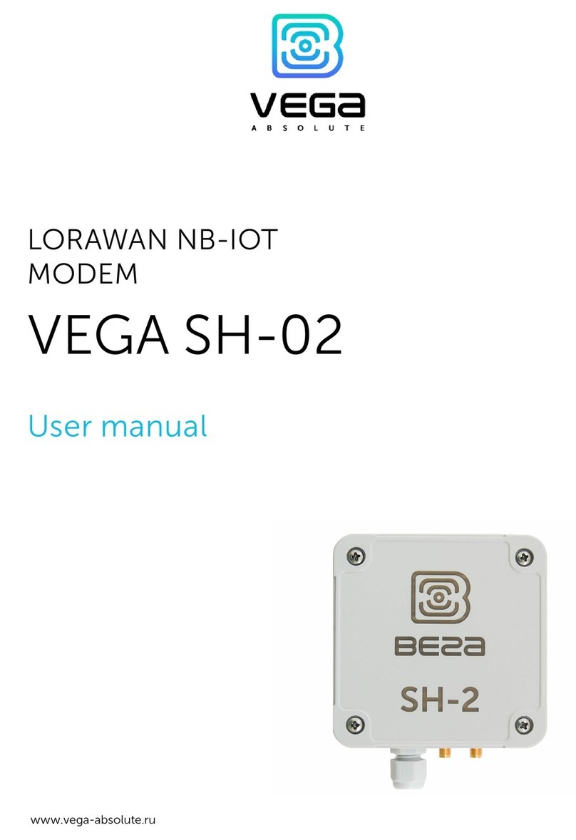
Vega Absolute SH-2 User manual

www.vega-absolute.ru
LORAWAN®UNIVERSAL
MODEM
VEGA SH-2
USER MANUAL
DOCUMENT REVISION
FIRMWARE VERSION
07 2.0.1 and higher

Vega SH-2 / User Manual
2 Revision 07 by 20 Sept 2021
CONTENTS
INTRODUCTION............................................................................................................................................................................4
1 DESCRIPTION AND OPERATION ............................................................................................................................................5
Device description ....................................................................................................................................................................5
Comunication and data collection algorithm .....................................................................................................................5
Functional ...................................................................................................................................................................................7
Marking ........................................................................................................................................................................................7
2 SPECIFICATION ..........................................................................................................................................................................8
Device specification..................................................................................................................................................................8
Default device settings .............................................................................................................................................................9
3 OPERATION...............................................................................................................................................................................10
Device appearance..................................................................................................................................................................10
Contacts ....................................................................................................................................................................................12
Indication ..................................................................................................................................................................................14
Button on the board ...............................................................................................................................................................15
Mounting Recomendations...................................................................................................................................................15
4 COMMUNICATION PROTOCOL ...........................................................................................................................................18
Vega SH-2 modem transmits the following types of packets to the LORAWAN®NETWORK.................................18
1. Packet with telemetry...............................................................................................................................................18
1.1. Standard subpacket ..............................................................................................................................................18
1.2. Subpacket timestamp...........................................................................................................................................19
1.3. Subpacket 1-Wire ..................................................................................................................................................19
1.4. Subpacket ModBus ...............................................................................................................................................20
2. Settings packet...........................................................................................................................................................21
3. Informational packet ................................................................................................................................................22
4. Packet with time correction request......................................................................................................................22
VEGA SH-02 modem receives packets of the following types by LORAWAN®..........................................................23
1. Packet with time correction ....................................................................................................................................23
2. Packet with request of settings...............................................................................................................................23
3. Packet with settings ..................................................................................................................................................23
5 STORAGE AND TRANSPORTATION REQUIREMENTS ......................................................................................................24
Vega SH-2 / User Manual
3
Revision 07 by 20 Sept 2021
6 CONTENT OF THE PACKAGE ................................................................................................................................................25
7 WARRANTY ................................................................................................................................................................................26

Vega SH-2 / User Manual
4 Revision 07 by 20 Sept 2021
INTRODUCTION
This manual is designated for Vega SH-2 modem (hereinafter – the modem)
manufactured by Vega-Absolute OOO and provides information on powering and activation
procedure, control commands and functions of the modem.
This manual is targeted at specialists familiar with installation work fundamentals of
electronic and electrical equipment.
Vega-Absolute OOO reserves the right to make changes to the manual related to the
improvement of equipment and software, as well as to eliminate typos and inaccuracies,
without prior notice.

Vega SH-2 / User Manual
5
Revision 07 by 20 Sept 2021
1 DESCRIPTION AND OPERATION
DEVICE DESCRIPTION
Vega SH-2 universal modem is designed for collection the data from external
connected devices, further accumulating and transmitting of this information in the
LoRaWAN®network.
The modem has two digital inputs which may be configured as pulse or security.
Besides the device has two analog inputs, 1-Wire and RS-485 interfaces.
The modem is powered by a one or two 6400 mAh built-in battery or an external
power supply 5…55 V.
The internal clock is set automatically when device connected to the "Vega LoRaWAN
Configurator" via USB, also adjustable via LoRaWAN®.
The modem can transmit collected data via LoRaWAN1technology.
COMUNICATION AND DATA COLLECTION ALGORITHM
Before using the modem, it must be activated in the LoRaWAN®network.
Vega SH-2 supports two activation methods in the LoRaWAN®network - ABP and
OTAA.
ABP method. After pressing the start button, the device immediately starts working in
the "Active" mode.
OTAA method. After pressing the start button, the device makes three attempts to
connect to the network within the set frequency plan. After the activation in the LoRaWAN®
network is confirmed, the device sends a signal (LED flashing for 3 seconds) and switches to
the "Active" mode. If all attempts are fail, the modem will go into a low power mode for a day,
after which it will try to register in the network again. The modem will try again once a day
until it registers successfully.
The device forms the data packet with current state with a configurable period from 5
minutes to 24 hours. The packets stored in the device memory and transmitting during the
next communication session with the LoRaWAN®network.
Examples
If the data collection period is set to 24 hours the packet is formed at 00.00 on the
internal clock of the device
If the data collection period is 12 hours then at 00.00 and at 12.00, and so on.
1The device can operate using NB-IoT technology. To do this, you need to install the firmware for the NB-15 on the
device. For details, see the NB-15 “User manual”.

Vega SH-2 / User Manual
6 Revision 07 by 20 Sept 2021
The adjustable data transfer period can be 5, 15, 30 minutes and 1, 6, 12 and 24 hours.
When beginning of communication session, the device starts sending packets with readings
from the earliest packet. The time of data transmitting cannot be specified, it’s defined in
random way for every device in chosen period of transmission from the moment of
connection to the network.
Example
The data transmission period is set to 30 minutes, the settings are applied at 16:40. The
device randomly selects the packet transmission time in a half-hour period from 16:40 to 17:10,
for example, 16:41. Thus, packets from this device will be transmitted at 16:41, 17:11, 17:41,
18:11, and so on every 30 minutes according to the device's internal clock.
The internal clock is set automatically when you connect to the device through USB,
also can be adjust via LoRaWAN®network.

Vega SH-2 / User Manual
7
Revision 07 by 20 Sept 2021
FUNCTIONAL
Vega SH-2 universal modem is an A class device (LoRaWAN®classification) and has the
following features:
ADR support (Adaptive Data Rate)
Sending of confirmed packets (configurable)
Inputs switching to the “Security” mode for connection of external sensors etc.
Saving non-transmitted packets in device memory
Time referencing readings by internal clock
Communication in case of security inputs actuation
Temperature measurement
Charge measuring of the built-in battery (%)
MARKING
Device marked with sticker that contain the next information:
oDevice model;
oDevEUI;
oMonth and year of manufacture;
Sticker located in three places – on device case, in factory certificate and on
the packing box.
Besides, there is an additional sticker located on the packing box and contains:
oInformation about firmware version;
oQR-code containing DevEUI and keys for device registration in network via
OTAA method.

Vega SH-2 / User Manual
8 Revision 07 by 20 Sept 2021
2 SPECIFICATION
DEVICE SPECIFICATION
MAIN
Digital inputs 2
Analog inputs 2
Interface 1-Wire / RS-485 (modbus)
USB-port micro-USB, type B
Operating temperatures -40…+85 °С
Communication channels LoRaWAN®
Internal temperature sensor yes
Communication period 5, 15, 30 minutes, 1, 6, 12 or 24 hours
Data collection period 5, 15, 30 minutes, 1, 6, 12 or 24 hours
Memory amount for storing packets 100 packets
LoRaWAN®
LoRaWAN®class A
Quantity of LoRaWAN®channels
16
Frequency plans supported by default
RU868, EU868, KZ865, custom
(EU868 based)
Frequency plans available as order option IN865, AS923, AU915, KR920, US915
Activation type ABP or OTAA
Type of the LoRaWAN®antenna external
Sensitivity -138 dBm
Radio coverage in restrained urban conditions up to 5 km
Radio coverage within line of sight up to 15 km
Transmitter power by default 25 mW (configurable)
POWER
Built-in battery 6400 /12800 mAh
External power supply 5…55 V
CASE
Housing dimensions (without cable gland and SMA-
connector)
96 х 96 х 50 mm
Ingress protection rating
IP67
PACKAGE
Package dimensions
165 x 118 x 57 mm
Weight
0,410 kg

Vega SH-2 / User Manual
9
Revision 07 by 20 Sept 2021
DEFAULT DEVICE SETTINGS
PARAMETER
VALUE
Frequency plan RU868
Activation type OTAA
Adaptive Data Rate ON
Confirmed Uplinks OFF
Rx 1 Delay 1 second
Join Accept Delay
5 seconds
Uplink number of transmissions 1
Data rate DR0
Power 14 dBm
Communication period 24 hours
Data collection period 24 hours
Time zone UTC +00:00
Inputs operate in mode pulse
For changing the device settings, you need to connect to it with “Vega LoRaWAN
Configurator” application. You can download app on the iotvega.com site in SOFT section as
well as User Manual for configurator. Go to the app page.

Vega SH-2 / User Manual
10 Revision 07 by 20 Sept 2021
3 OPERATION
DEVICE APPEARANCE
Vega SH-2 is represented in gray plastic case screwed together. The case of the device
is equipped with a cable gland of standard size M12. A seal is installed inside the gland, which
ensures compliance with the declared degree of protection of the device case.
1 – screw ø 4 mm х
2 – cable gland of standard size M12 for installation of round cable ø 5-6 mm
3 – external antennas input
All of elements for manage and indication as well as connecting contacts are placed on
the board inside the case.
Internal structure of the cable gland
1
3
2

Vega SH-2 / User Manual
12 Revision 07 by 20 Sept 2021
CONTACTS
Description of contacts in the table below.
Contact
Name on the board
Description
1
COUNT1 Digital input 1
2
COUNT2
Digital input 2
3
GND
Ground
4
GND
Ground
5
ADC1
Analog input 1 (0…21 В)
6
ADC2
Analog input 2 (0…21 В)
7
RS485_A
RS-485 Interface A
8
RS485_B
RS-485 Interface B
9
ONE_WIRE 1-Wire Interface
10
GND Ground
11
+V_EXT External power +
12
GND External power -
Digital inputs COUNT1 and COUNT2 may operate in pulse or security mode. If the
input has not connected there is a logic ‘1’.
In the pulse mode the modem counts the number of pulses at the input. Fixation is by
the impulse slump. In the security mode the modem monitors the input state change and
send an alarm message into the network by the one of events: security circuit close, unclose

Vega SH-2 / User Manual
13
Revision 07 by 20 Sept 2021
or both of it. You can choose the event for security input triggering via the “Vega LoRaWAN
Configurator” application.
Analog inputs ADC1 and ADC2 may be used for measuring an external voltage from 0
to 21 V.
RS-485 (modbus) and 1-Wire interfaces cannot connecting at the same time. Switching
between two interfaces carried out with jumpers on the XP4 and XP5 connectors on the
board. In addition, in the LoRaWAN®configurator, go to the “Interface settings” section and
select the 1-Wire / ModBus input mode.
The 1-Wire interface allows you to connect up to 10 external temperature sensors. To add a
sensor in the Vega LoRaWAN®Configurator program in the "states" tab, click the "Add one
sensor" button, or click the "Add all sensors" button to add all sensors present on the 1-Wire
line at a time.
Each sensor is assigned a number - in the order of addition, if the sensors are added to
the bus one at a time, and in random order, if the sensors were added all at once. The number
is used to identify the position of the sensor on the 1-Wire bus. You can set the sensor
number in accordance with the ordinal position on the bus using the Configurator button
"Change the order of sensors". All sensors can be deleted from memory by pressing the
"Delete all sensors" button.
Jumpers
disposition for
RS-485 interface
operating
Jumpers
disposition for
1-Wire interface
operating

Vega SH-2 / User Manual
14 Revision 07 by 20 Sept 2021
INDICATION
There is a red LED on the board. The indication is used when the device is activated in
the LoRaWAN®network, and when the operating modes are changed.
LED signal
Meaning
Flash every 5 seconds Device not sleeping/USB connection
Series of short flashings Linking to the network
One long flashing The device connected to the network
and is in active mode
Three long flashings Device switched to the «Storage» mode
Red LED on the
board

Vega SH-2 / User Manual
15
Revision 07 by 20 Sept 2021
BUTTON ON THE BOARD
The device has a button on the board that is responsible for switching operating
modes.
The button on the device board works as follows.
Press
Value
Short press (0.5 seconds) Switch to “Active” mode
Button hold up to 3 flashes of red LED generating a packet into a black box
Button hold up to 5 flashes of red LED Switch to “Storage” mode
MOUNTING RECOMENDATIONS
To provide the stable radio between the gateway and the end device is recommended
avoiding the device installation in the places which are barriers for the radio signal getting
through like a reinforced floors and walls, a basement, an underground facilities and wells, a
metal case etc.
Start button located
on the board

Vega SH-2 / User Manual
16 Revision 07 by 20 Sept 2021
The necessary stage for the network deploying including a big quantity of end devices
is a radio planning work with nature experiments.
Before starting mounting work, you must make sure that the latest
firmware version is installed on the equipment
For mounting you will need:
wire stripper;
laptop.
Step by step mounting be like:
1. Setting the devices and connecting them to the network are usually carried out in
the office (see Network Deployment Manual).
2. Determination of suitable places for mounting at the object with a network tester.
3. De-energizing the connected equipment, metering devices, etc.
4. Placement of wires in the cable gland. It must be remembered that the wires must
be combined into a single round cable with a diameter of 5-6 mm.
A seal is installed inside the cable gland, which ensures compliance with
the declared degree of protection of the device case. When removing the
seal, as well as when installing a cable of a different diameter or cross-
section, the performance of the device may deteriorate up to failure due
to moisture penetration into the housing
5. Connecting all necessary wires to the SH-2 contacts.
6. When the power is connected for the first time, the device automatically switches
to the "Active" mode and begins to register in the network. But if the device with the
connected battery was switched to the "Storage" mode by pressing the start button
for a long time (more than 5 seconds) (see the section "Button on the device
board"), then turning on is carried out by pressing the button.
7. By the laptop you can make sure that the device successfully sends the data.

Vega SH-2 / User Manual
17
Revision 07 by 20 Sept 2021
8. Before assembling the device, it is necessary to reset the pulses accumulated during
testing and connection by switching the device to the "Storage" mode by pressing
the button for 5 seconds.
9. Start the device by pressing launch button.
10. Assembling the device.
The Vega SH-2 modem can be powered from either an external power source or
built-in battery. To operate from the built-in battery, you must connect the battery connector
to the one of power connectors on the board which XP7 or XP6 marked. In case of operation
with two batteries you should use both connectors.
Connectors for
batteries

Vega SH-2 / User Manual
18 Revision 07 by 20 Sept 2021
4 COMMUNICATION PROTOCOL
This part describes the Vega SH-2 data exchange protocol with LoRaWAN®network.
In fields consisting of several bytes, the little-endian byte order is used
VEGA SH-2 MODEM TRANSMITS THE FOLLOWING TYPES OF PACKETS
1. Packet with telemetry
Sent regularly to LoRaWAN®port 2.
Since the amount of telematic data from the device exceeds the 51 bytes limit of the
LoRaWAN®protocol, the packet is split into sub-packets. In this case, the format of the
subpacket is determined by its first byte type.
The telemetry packet sent to LoRaWAN®port 2 contains the reason field, which defines
the reason (event) of the packet formation. Once formed, the bag is placed in a black box. If the
event belongs to alarming* (see the table below), then an unscheduled attempt to send
packets is performed.
Reason Event
1
Packet generated on schedule
2*
Alarm on the «COUNT1» input
3*
Alarm on the «COUNT2» input
4
Configurator command
5
By button on the device
1.1. Standard subpacket
UTC - collection time of data transmitted in this packet
bat - battery charge percentage
t°C - processor temperature
pulse1 and pulse2 - number of pulses at digital outputs 1 and 2, respectively
ADC 1 and ADC2 - voltage values (in mV) at analog inputs 1 and 2, respectively.
The subpacket size is 20 bytes.
0A
type
reason
UTC
pulse 1
ADC 1
bat
t°C
pulse 2
ADC 2

Vega SH-2 / User Manual
19
Revision 07 by 20 Sept 2021
Example
0A 04 B009E760 63 1B 100A0000 20000000 0800 1000
Reason = by Configurator command, Bat = 99%, t°C = 27, pulse 1 = 2576, pulse 2 = 32, ADC 1
= 8 mV, ADC2 = 16 mV.
1.2. Subpacket timestamp
UTC - the collection time of the data transmitted in this packet is used if the data is split
into several radio packets.
Subpacket size is 6 bytes.
1.3. Subpacket 1-Wire
Len - shows the size of the data following the len byte (size is in bytes). Information
about each sensor is encoded in a 16-bit word in the Little endian format, where: 11 bits -
temperature value (temperature_value), 5 bits - sensor number (assigned automatically or
via the configurator).
A subpacket with 1-wire data is dynamic - its length can vary depending on the number
of connected 1-wire sensors.
Formula for calculating temperature in degrees Celsius:
t°C = (temperature_value - 600Dec)/10
A 1-bit change in temperature_value corresponds to a 0.1 degree Celsius change.
0B
type
reason
UTC
0С
type
len
t 1
2*n
t 2
t 3
t n
1
temperature_value
n – sensor
number
bit 0
bit 15
54
0B
0
1
1
1
0
0
1
0
1
0
0
0
0
0
0
Sensor № 1, temperature 25.2 °C

Vega SH-2 / User Manual
20 Revision 07 by 20 Sept 2021
Temperature examples:
Temperature value
Temperature (0-10 bits)
HEX
DEC
0x000
0
– 60,0 °C
0x032
50
– 55,0 °C
0x258
600
0,0 °C
0x259
601
+ 0,1 °C
0x73A
1850
+ 125 °C
0x7FF 2047
Sensor not found
A radio packet can be composed of several sub-packets. For example, standard subpacket +
1-wire subpacket. If the 1-wire data exceeds the maximum allowable radio packet size, then
the next radio packet is generated with data from the remaining 1-wire sensors, with a
timestamp subpacket attached in front of it.
1.4. Subpacket ModBus
The len byte indicates the size of the data following the len byte (size is in bytes).
The upper nibble of the head byte indicates the number of the read operation, which can take
values from 1 to 10. (corresponds to the order of the settings presented on the ModBus
Settings tab in the LoRaWAN®configurator). The number of the read operation determines
the settings: the ModBus function, the address of the start register for reading, the number of
registers / bit to be read.
The least significant tetrad of the head byte indicates the number of subsequent data bytes of
the data field
The data field contains the data read from the ModBus device in the specified read operation.
Attention, the format of the data field is big endian.
0B
type
reason
Subpacket timestamp
UTC
Radio packet with information about 1-wire sensors
0С
type
len
Subpacket 1-wire
t 1
2*n
t 2
t 3
t n
0D
type
len
Subpacket ModBus
head 1
Subpacket with 1-modbus data
data 1
data 2
Number of
Bytes read
Number of
Reading
operation
bit 7
1
0
0
0
0
1
0
the size of the data 2 field is 4 bytes
0
12
24
head 2
len
Table of contents
Other Vega Absolute Modem manuals

Vega Absolute
Vega Absolute Vega NB-15 User manual

Vega Absolute
Vega Absolute NB-14 User manual

Vega Absolute
Vega Absolute SH-02 User manual

Vega Absolute
Vega Absolute VEGA NB-13 User manual

Vega Absolute
Vega Absolute SI-13 User manual

Vega Absolute
Vega Absolute NB-12 User manual

Vega Absolute
Vega Absolute NB-12 User manual