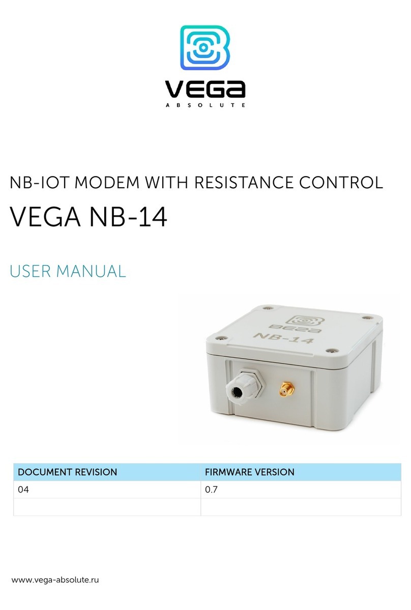
Vega Absolute NB-12 User manual

www.vega-absolute.ru
NB-IOT MODEM WITH 4-20 MA INTERFACE
VEGA NB-12
USER MANUAL
DOCUMENT REVISION FIRMWARE VERSION
5 1.2b

Vega NB-12 / User Manual
2 Revision 05 of 21 January 2022
CONTENTS
INTRODUCTION......................................................................................................................................................................... 3
1 DEVICE PURPOSE AND OPERATION PRINCIPAL.............................................................................................................. 4
Device Purpose ....................................................................................................................................................................... 4
Operation Algorithm.............................................................................................................................................................. 4
Functional ................................................................................................................................................................................ 4
Marking ..................................................................................................................................................................................... 5
2 SPECIFICATION ....................................................................................................................................................................... 6
Device Specification .............................................................................................................................................................. 6
Default Device Settings ......................................................................................................................................................... 7
3 OPERATION.............................................................................................................................................................................. 8
Device Appearance ................................................................................................................................................................ 8
Contacts ................................................................................................................................................................................. 10
Pulse Inputs Settings............................................................................................................................................................ 11
Hall Sensor ............................................................................................................................................................................. 13
Buttons ................................................................................................................................................................................... 14
Indication ............................................................................................................................................................................... 15
Mounting Recomendations................................................................................................................................................ 16
4 COMMUNICATION PROTOCOL ........................................................................................................................................ 18
5 STORAGE AND TRANSPORTATION REQUIREMENTS ................................................................................................... 22
6 CONTENT OF THE PACKAGE ............................................................................................................................................. 23
7 WARRANTY ............................................................................................................................................................................. 24

Vega NB-12 / User Manual
3
Revision 05 of 21 January 2022
INTRODUCTION
This manual is designated for Vega NB-12 modem with 4-20 mA interface (hereinafter –
the modem) manufactured by Vega-Absolute OOO and provides information on powering and
activation procedure, control commands and functions of the modem.
This manual is targeted at specialists familiar with installation work fundamentals of
electronic and electrical equipment.
Vega-Absolute OOO reserves the right to make changes to the manual related to the
improvement of equipment and software, as well as to eliminate typos and inaccuracies,
without prior notice.

Vega NB-12 / User Manual
4 Revision 05 of 21 January 2022
1 DEVICE PURPOSE AND OPERATION PRINCIPAL
DEVICE PURPOSE
Vega NB-12 modem is designed for collecting readings from devices with current loop
interface 4-20 mA, with analog output, pulse output or 1-Wire interface, further accumulating
and transmitting of this information in NB-IoT network.
In addition, Vega NB-12 can be used as a security device – two additional inputs operate
in security mode, there is also Hall sensor.
The modem can be used for any sensors and industrial equipment with interface 4-20
mA or 1-Wire such as temperature sensors, humidity sensors, pressure sensors.
Equipment with NAMUR pulse output is not supported
The modem may be powered by one or two batteries with capacity 6400 mAh.
OPERATION ALGORITHM
The readings collecting from the meter with a configurable period 5, 15, 30 minutes, 1,
2, 3, 4, 6, 12 or 24 hours. The readings stored in the device memory and transmitting during the
next communication session with the NB-IoT network.
The adjustable data transfer period can be equal to 5, 15, 30 minutes, 1, 2, 3, 4, 6, 12 and
24 hours. Data transferring in random point in time during set period. At the next
communication session, the device starts sending accumulated packets with readings, from
the earliest to the latest.
The device operates with confirmation all the time and send the next packet only after
receiving a confirmation of the delivery of the previous one. If such confirmation was not
received, NB-12 completes the communication session until the next one according to the
schedule. Herewith, the device continues to collect data according to the data collection
period and store it in memory. Non-transmitted packets remain in the device memory until the
next communication session.
The internal clock is set automatically when device connected to the "Vega NB-IoT
Configurator" via USB.
FUNCTIONAL
Vega NB-12 modem has the following features:
Interface ‘current loop’ 4-20 mA
Interface 1-Wire for connecting temperature sensors (up to 10 pc)
Vega NB-12 / User Manual
5
Revision 05 of 21 January 2022
Analog input for voltage measurement from 0 to 3 V
Two inputs operating in the «security» mode for connecting the external leakage
and safety sensors, etc. with ability to configure as pulse to count input pulses
Queue of sending when delivery is not possible
Time referencing of readings by internal clock (UTC)
Extra communication when current on the ‘current loop’ interface is out of
specified thresholds
Communication in case of security inputs or Hall sensor actuation
Measurement of temperature inside housing
Charge measuring of the battery (%)
Ability to filter the pulses by the duration
MARKING
Device marked with sticker that contain the following information:
Device model;
IMEI;
Month and year of manufacture.
Sticker located in three places – on device case, in factory certificate and on the packing
box.

Vega NB-12 / User Manual
6 Revision 05 of 21 January 2022
2 SPECIFICATION
DEVICE SPECIFICATION
MAIN
Analog inputs
1
Interfaces
1-Wire, current loop 4-20 mA
Security/pulse inputs
2
USB-port
micro-USB, type B
Operating temperatures
-40…+85 °С
Built-in temperature sensor
yes
Hall sensor
yes
Quantity of black box records
up to 100 000
CELLULAR COMMUNICATIONS
Supported Cellular Standards LTE Cat NB1
Data transfer protocol MQTT
Battery Life 1 year if the data transferring once a day
LTE NB-IoT antenna type external
POWER
Built-in battery
6400 mAh (one or two, depending on
delivery conditions)
CASE
Housing dimensions
95 х 95 х 50 mm
Ingress protection rating IP67
PACKAGE
Dimensions
165 x 118 x 57 mm
Weight 0.350 kg

Vega NB-12 / User Manual
7
Revision 05 of 21 January 2022
DEFAULT DEVICE SETTINGS
PARAMETER VALUE
Confirmed Uplinks
OFF
Communication period
24 hours
Data collection period 24 hours
Time zone UTC +00:00
Guard inputs operate On short
Hall sensor ON
Send network statistics OFF
Pulse filtering settings 50 ms for pulse and pause
For changing the device settings, you need to connect to it with “Vega NB-IoT
Configurator” application. You can download app on the iotvega.com site in SOFT section as
well as User Manual for configurator. Go to the app page.

Vega NB-12 / User Manual
8 Revision 05 of 21 January 2022
3 OPERATION
DEVICE APPEARANCE
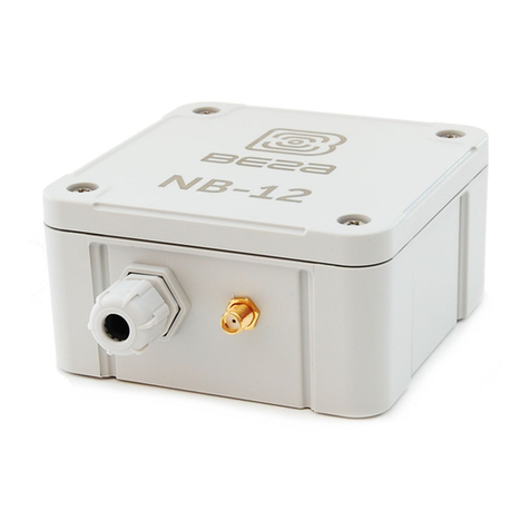
Vega NB-12 is represented in gray plastic case which has six screws and mounting for
DIN-rail. The device case is equipped with a hermetic gland of M12 size. A sealant is installed
inside the gland, ensuring compliance with the declared Ingress Protection rating of the device
case.
2 – cable gland of M12 size for installing the cables and wires with circular cross-section
with a diameter of 5...6 mm
3 – input of external antenna
1
2 3
Internal structure of cable gland

Vega NB-12 / User Manual
9
Revision 05 of 21 January 2022
All of elements for manage and indication as well as connecting contacts are placed on
the board inside the case.
4 – input for connecting an external antenna
5 – contacts
6 – USB-port
7 – manage buttons
8 –LED indicators
9 – SIM holder
10 – input for connecting a battery
4
5
6
9
10
8
7

Vega NB-12 / User Manual
10 Revision 05 of 21 January 2022
CONTACTS
Description of contacts assignment is in table below. When connecting a radio modem
to external devices with pulse outputs, consider the circuit design of its pulse inputs.
Contact PCB designation Description
1
GND
Ground
2 ALARM1 Security/pulse input 1
3 GND Ground
4 ALARM2 Security/pulse input 2
5 GND Ground
6
A_INPUT
Analog input
7
GND
Ground
8 ONE_WIRE 1-Wire
9 CL+ 4-20 mA «+»
10 CL- 4-20 mA «-»
There are two security inputs on the boars which allows to connect circuits with the
following types of NO contacts:
reed switch;
mechanical pushbutton;
open-collector output.
Circuit design of the pulse inputs

Vega NB-12 / User Manual
11
Revision 05 of 21 January 2022
The device monitors status changes on the security inputs and when the security input
triggers, the device is activated and sends an alarm message to the network. The trigger
mechanism is configured through the program "Vega NB-IoT Configurator".
Security inputs can operate as pulse.
Equipment with NAMUR pulse output is not supported
CL+ and CL- contacts are used for connecting an external sensor with 4-20 mA
interface. Scheme for connecting is shown on the picture below.
PULSE INPUTS SETTINGS
When you connect the modem to metering devices with a pulse output, it is necessary
to consider the features of the pulse of a specific type of metering device: bounce, minimum
pulse and pause duration. To do this, it is necessary to record the characteristics of the pulse
with an oscilloscope or obtain information from the manufacturer of the meter.
The modem has a special software pulse filter. The filter is represented by two settings
for each pulse input (see section 4, “Settings” tab). Consider the features of filtering settings for
different pulse outputs.
1) Mechanical pulse output
Usually, the mechanical pulse output in metering devices is implemented on a reed
switch, but it can also be a button or other mechanics. The main problem with such outputs is
contact bounce. At a moment of falling and rising, there are many additional impulses that need
to be no considered in the calculation. In addition, the pulse duration floats and depends on
the current flow rate of the meter. For correct counting, it is necessary to determine the
minimum useful pulse duration and the minimum pause between useful pulses (all that is less
is bounce). The obtained values must be set in the modem settings.
The minimum useful pulse duration is the pulse duration that the meter produces at the
maximum flow rate (the maximum flow rate is indicated in the meter's passport). This duration
does not include bounce time. The minimum pause duration can be set equal to the minimum

Vega NB-12 / User Manual
12 Revision 05 of 21 January 2022
pulse width, or longer if necessary. Usually, the pause between pulses is an order of magnitude
higher.
2) 2) Electronic pulse output
The electronic pulse output has no bounce (open collector output). This output usually
has a fixed pulse width. For the modem to fix the pulse, it is necessary to set in the settings the
minimum pulse duration less than the actual pulse duration issued by the meter.

Vega NB-12 / User Manual
14 Revision 05 of 21 January 2022
BUTTONS
There are two buttons on the board which can help you to manage the device. Buttons
are described in the table below.
RESET
Short pressing Device reloading
INIT
Pressing for 1 second Registration at the network
Pressing for 2 seconds Data transmitting
Pressing for 3 seconds LTE-modem switching off
Pressing for 4 seconds To form record to the black box
When you hold down the button, the red LED starts flashing once a second, which will
help you to find out the duration of pressing. Pressing for 1 second corresponds to one flash of
the LED, pressing for 2 seconds corresponds to two and so on.
INIT button
RESET button
INIT button
RESET button

Vega NB-12 / User Manual
15
Revision 05 of 21 January 2022
INDICATION
There are two LEDs on the board: red and blue. Blue LED VD19 shows LTE-modem state,
and red LED VD18 – the device state.
LTE-modem
Short flash every three
seconds Device search the network
Short flash every
second
Device successfully registered and it is
in the network
Two short flashes every
one second Device transmits data to the network
No light LTE-modem switched off
Device
Short flash every
second Battery charge is lower than 5%
Short flash every five
seconds Device in the ‘Operation’ mode
No light
Device in the ‘Sleep’ mode or switched
off
LEDs location oh
the board

Vega NB-12 / User Manual
16 Revision 05 of 21 January 2022
MOUNTING RECOMENDATIONS
The counter shall be installed and adjusted by qualified specialists to ensure proper
operation of the device.
When connecting the pulse output of the metering device to the counting input of the
modem, it is recommended to use cables with a shielding braid, and to install the metering
device with the modem away from sources of radio interference. It is recommended to use a
two-wire shielded cable. The shield is connected on the side of the impulse counter to its
ground.
1st wire – signal from pulse output is connecting to contact COUNT
2nd wire – ground is connecting to contact GND
Shield – is connecting to contact GND
Before starting mounting work, you must make sure that the latest
firmware version is installed on the equipment
For mounting you will need:
SIM-card;
wire stripper;
laptop.
Step by step mounting be like:
1. Installing SIM-card into holder;
2. Setting the device through the “Vega NB-IoT Configurator” – the first and second
steps are usually carried out in the office.
3. De-energizing the connected equipment, metering devices, etc.
4. Placement the wires in the cable gland. It must be remembered that the wires must
be united in one cable of circular cross-section with diameter of 5…6 mm.
Inside the cable gland there is a sealant ensuring compliance with the
declared Ingress Protection rating of the device case. When removing
the sealant, as well as when installing wires of a different diameter or
cross-section, device performance may deteriorate until failure due to
moisture entering the case

Vega NB-12 / User Manual
17
Revision 05 of 21 January 2022
5. Connecting all necessary wires to the contacts.
6. Connecting the battery at the connector. After the battery connection the device
loads and comes to sleep until the next communication session.
7. If you need to test the data transmitting, then press and hold the INIT button for the
2 seconds.
8. Before assembling the device, you can reset the pulses accumulated during testing
and connection through the “Vega NB-IoT Configurator” if it is necessary.
9. Assembling the device.
Location of the SIM
slot on the board (if
there is)
Location of the
battery connectors
on the board

Vega NB-12 / User Manual
18 Revision 05 of 21 January 2022
4 COMMUNICATION PROTOCOL
Data is transmitted via MQTT protocol. You should specify in the device settings the
address and port of the server where the data will be sent. Those settings specified in
application “Vega NB-IoT Configurator”. It must be MQTT broker as a server (received side).
You should specify in the device settings the address and port of the broker. Also, you should
specify a topic name where the data published and a client name – the name which the device
use for publishing. All those settings specified in “Vega NB-IoT Configurator” in part “MQTT
settings”. For watching the data sending by the device you should deploy MQTT broker on a
PC and become subscribed on MQTT broker with any application.
Vega NB-12 sends the message on the server as a text of JSON format. See example
below.
{
"Message": {
"dev": "VEGA NB-12 1.2b",
"IMEI": "867723030031164",
"IMSI": "250023039331786",
"ICCID": "897010230393317862",
"num": 4,
"UTC": 1638768629
},
"CellStatus": {
"SQ": 25,
"EARFCN": 1865,
"PCID": 292,
"RSRP": -697,
"RSRQ": -108,
"RSSI": -638,
"SNR": 184
},
"Telemetry": {
"reason": "time",
"UTC": 1638768606,
"bat": 99,
"temp": 27,
"ADC1": 1609,
"current": 26.28,
"bat_drop": 3.19,
"pulse1": 0,
"pulse2": 0,
"s_alarm1": 1,
"s_alarm2": 1,
"s_magnet": 0,
"s_curovr": 1,
"s_bde": 0,

Vega NB-12 / User Manual
19
Revision 05 of 21 January 2022
"onewire": {
"1": {
"t": 25.1,
"s": 0
},
"2": {
"t": 24.5,
"s": 0
},
"3": {
"t": 24.6,
"s": 1
},
"4": {
"t": 24.5,
"s": 0
},
"5": {
"t": -24.3,
"s": 0
},
"6": {
"t": 25.3,
"s": 0
},
"7": {
"t": 24.3,
"s": 0
},
"8": {
"t": 24.3,
"s": 1
},
"9": {
"t": -24.3,
"s": 1
},
"10": {
"t": 24.3,
"s": 0
}
}
}
}
Transcription of the message fields:

Vega NB-12 / User Manual
20 Revision 05 of 21 January 2022
Message – part with information about current message.
dev – name and version of the device firmware
IMEI – LTE-modem identifier
IMSI,ICCID – SIM-card (SIM-chip) identifiers
num – the number of the message
UTC – the date and the time of message sending in UTC format by Greenwich
CellStatus – part with information about the cellular state
SQ – gateway signal quality
EARFCN – the number of radio frequency channel (absolute)
PCID – physical network address
RSRP – input signal power
RSRQ – input signal quality
RSSI – indicator of the input signal power
SNR – signal to noise ratio
Telemetry – part with collected data (one packet)
reason – reason for packet forming*
UTC – the date and the time of message collecting in UTC format by Greenwich
bat – battery charge
temp – processor temperature
ADC1 – voltage on the input A_INPUT
current – measured current of the current loop interface
bat_drop – battery voltage value under load
pulse1– pulse number on the input 1
pulse2– pulse number on the input 2
s_alarm1 – state of ALARM1 input at the time of data slice ("0" - logic zero input,
"1" - logic one input)
s_alarm2 – state of ALARM2 input at the time of data slice ("0" - logic zero input,
"1" - logic one input)
s_magnet – the presence of an external magnetic field at the time of data slice
("0" - absent, "1" - presence)
s_curovr – flag for exceeding the current limits of the current loop interface
specified in the settings ("0" - the limit is not exceeded, "1" - the limit is exceeded)
s_bde - flag of the presence of a critical voltage drop of the battery under load
onewire – values of temperatures of sensors on 1-Wire bus (first field "1", “2” etc.
– sensor number, second field "t" - sensor temperature value, third field "s" – threshold
exceeding flag (“0” – no exceeding, “1” - thresholds exceeded))
*Possible values for Reason field (Reason for packet forming):
time – packet formed by the time (data collection period set up in the
Configurator for the device)
alarm1– packet formed by the alarm on the input "ALARM1" (communication
session initiated by this event)
Other manuals for NB-12
1
Table of contents
Other Vega Absolute Modem manuals

Vega Absolute
Vega Absolute NB-14 User manual

Vega Absolute
Vega Absolute NB-12 User manual

Vega Absolute
Vega Absolute SH-02 User manual

Vega Absolute
Vega Absolute SI-13 User manual

Vega Absolute
Vega Absolute VEGA NB-13 User manual

Vega Absolute
Vega Absolute Vega NB-15 User manual

Vega Absolute
Vega Absolute SH-2 User manual