LedSync820C User’s Manual
---------------------------------------------------------------------------------------------------
LED VIDEO PROCESSOR 6
III. Frontal panel operations
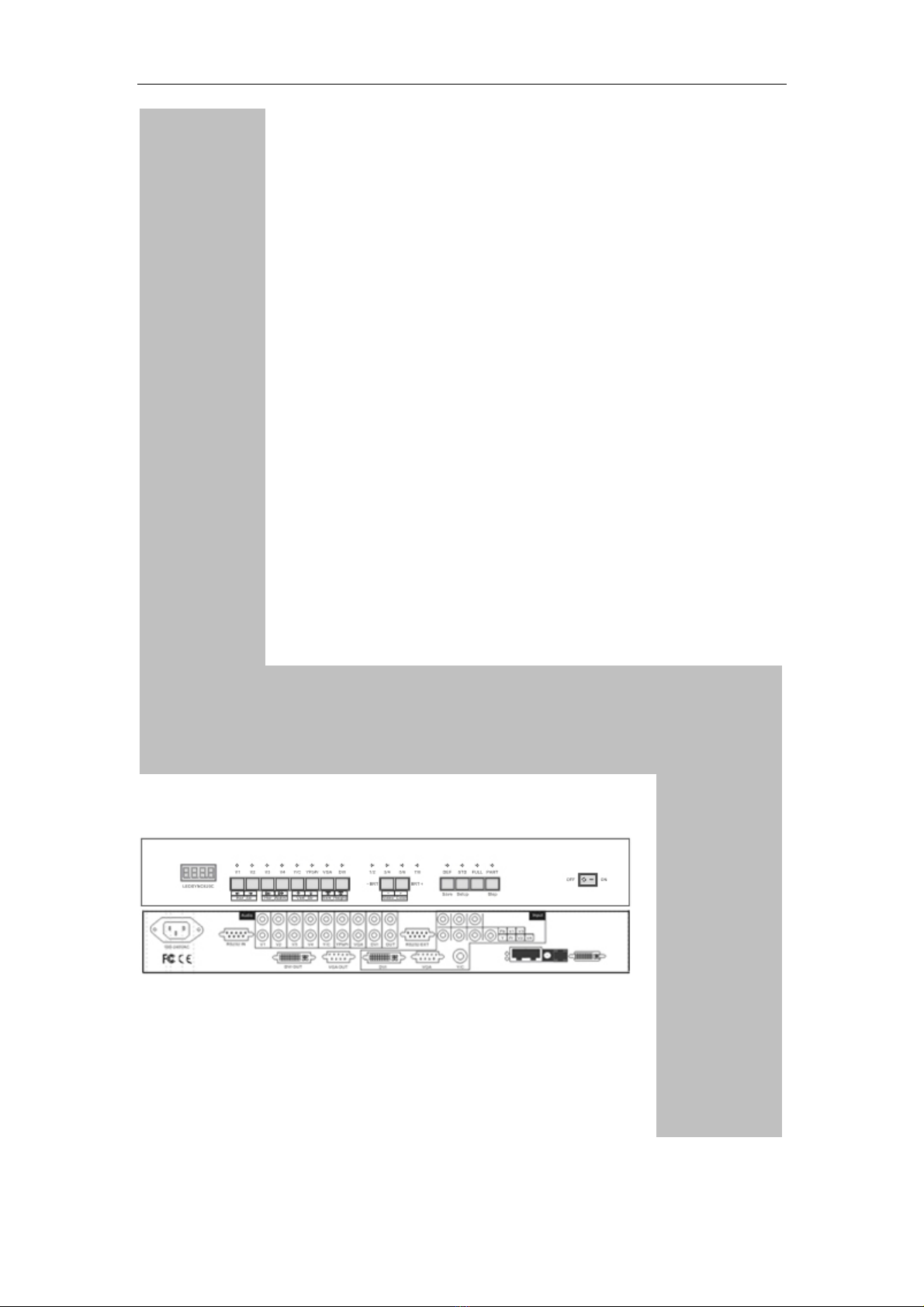
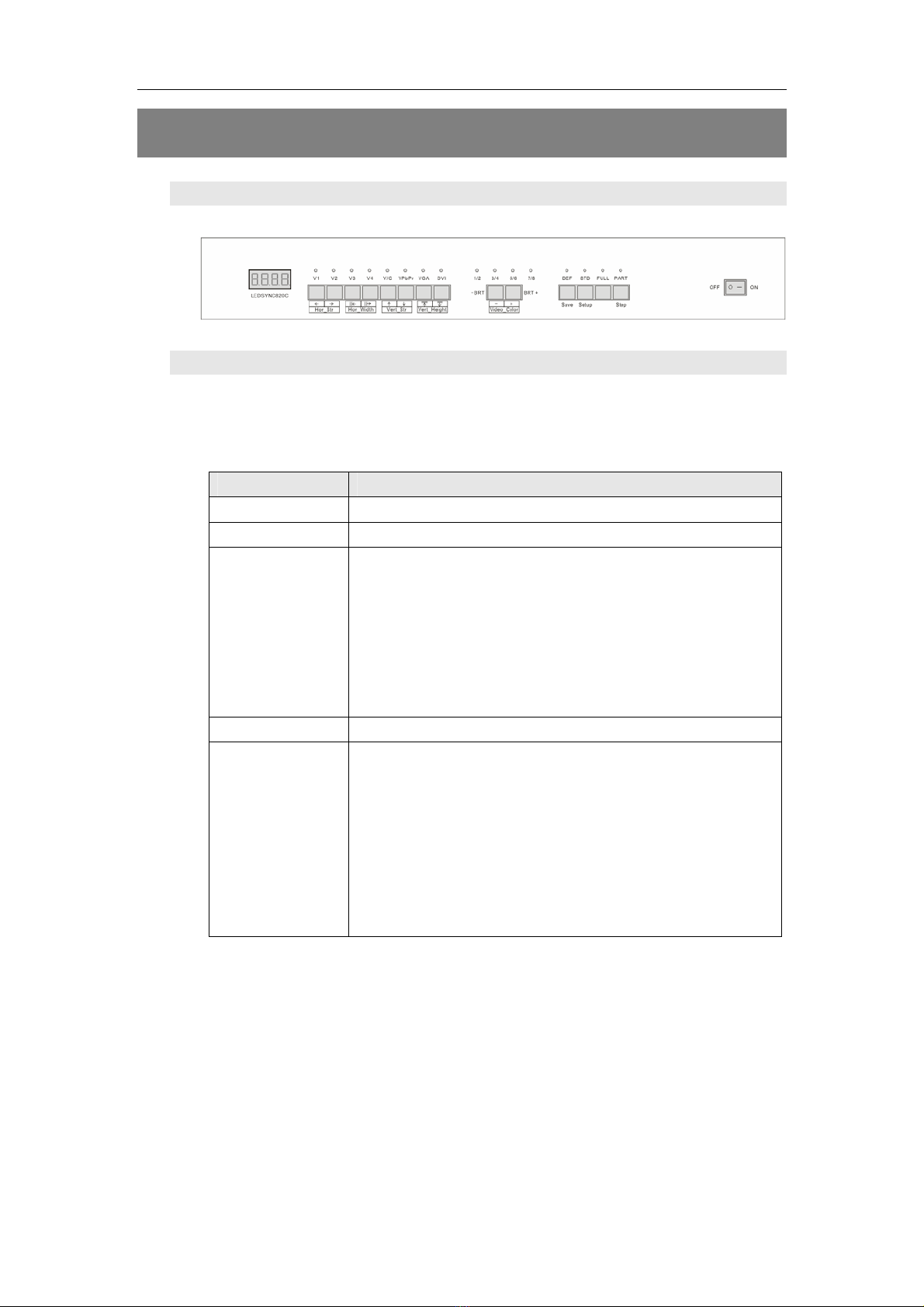
1. Diagram of frontal panel
Figure 3
2、Button operations:
LedSync820C have 14 buttons on frontal panel, after start-up all
these buttons are in operation mode. Their functions are described as
below:
1)Select input video source
Button names Description
V1~V4 Switch to V1~V4, composite video input
Y/C (S_Video) Switch to S-Video input
VGA Switch to computer analog signa input
Note: to get clarity computer image, you can click
the “VGA” button 6 times continuously, and then
you can click “VGA” button again and again to
change the computer image sampling phase,
when the computer image be displayed most
clearly, the adjustment is ok.
DVI Switch to computer digital signal input
YPbPr Switch to high-definition component video signal
input
Note: to get clarity HDTV image, you can click the
“YPbPr” button 6 times continuously, and then you
can click “YPbPr” button again and again to
change the HDTV image sampling phase, when
the HDTV image be displayed most clearly, the
adjustment is ok.
Switch audio input while operating above buttons, select the audio
signal input from corresponding video input to output it through Audio
OUT.
Notes: when user has selected input signal, if there are signal input
in corresponding signal input ports and are in LedSync820C formats,
the indicator above corresponding button will be illumed. However,
when there are no signal input in corresponding input ports, the
indicator above corresponding button will blink, and dark screen will be
displayed on the screen.