Veichi Electric VC-eNET User manual

1
VC-eNET User Manual
Thank you for purchasing the VC-eNET developed and produced by Suzhou VEICHI Electric Technology Co., Ltd. Before using our company's VC
series PLC products, please read this manual carefully, so as to better grasp the characteristics of the products and correctly install and use them. More
secure application and make full use of the rich functions of this product.
Tips:
Please read the operating instructions, precautions and cautions carefully before starting to use the product in order to reduce the risk of accidents.
Personnel responsible for the installation and operation of the product must be strictly trained to comply with the safety codes of the relevant industry,
strictly observe the relevant equipment precautions and special safety instructions provided in this manual, and carry out all operations of the equipment
in accordance with the correct operating methods.
1 Interface description
1.1 Interface description
The appearance of VC-eNET interface and user terminal is shown in Figure 1-1.
Figure 1-1 Appearance of the module interface
1.2 Access to the system
Through the expansion interface, the VC-eNET module can be connected with the VC series PLC main module. As shown in Figure 1-2
Push to the right
VC1-1614MAR
Figure 1-2 Schematic diagram of the connection between the communication module and the main module
1.3 Wiring Instructions
(1) Wire
VC-eNET mainly extends the main module of VC1 series to the left, and can provide one channel of Ethernet communication function. In order to
ensure that your communication is normal, it is recommended to use shielded network cable for network data transmission, without short circuit,

2
dislocation and poor contact; The length of the cable should not exceed 100m, otherwise the signal will be attenuated and normal communication will
be affected. The following specifications are recommended, and the network cables are shown in Table 1-1:
Project
Specification
Cable type
Flexible Crossover Cable, S-FTP,
Category 5
Standards met
EIA/TIA568A, EN50173,
ISO/IEC11801, EIA/TI Abulletin
TSB, EIA/TIA SB40-A&TSB36
Conductor cross section
AWG26
Wire type
twisted pair
Pair
4
Table 1-1 Standard specifications of network cables
Figure 1-3: Shielded network cable
2 Instructions for use
2.1 Indicator light description
project
Instruction
Signal indicator
PWR power indicator: When the main module is correctly connected, the indicator remains on;
RUN: Running indicator: the indicator flashes when the system connection is normal;
ERR: Error indicator light: the light is on when the communication is abnormal;
Expansion module interface
Expansion module interface, does not support hot plug
3 Module Features
1. VC-eNET is mainly used for VC1 series main module to expand one channel of Ethernet communication port.
2. VC-eNET only supports slave station, and supports up to four master stations to communicate with the module.
3. As the left expansion communication module of VC1 series, the VC-eNET module can be connected to at most one module on the
left of the PLC main unit.
4 Communication configuration
VC-eNET extended communication module parameter configuration needs to be configured in AutoStudio programming software. Such as IP address,
subnet mask, gateway address, etc.
Programming software configuration tutorial
1) New project, in the Project managerCommunication configEthernet
Configure Ethernet as required. This example is the default IP address.

3
Figure 4-1 Ethernet Configuration
2) After clicking the configuration, click "OK" to complete the communication parameter configuration.
3) The VC-eNET extended Ethernet module is only a slave station, and the IP address can be configured according to the needs.
5 Installation
5.1 Dimensions
VC-eNET
PWR
RUN
ERR
25
32
91.7
95.1
95
90
Figure 5-1 External dimensions and mounting hole size (unit: mm)
5.2 Installation method
The installation method is the same as that of the main module, please refer to "VC Series Programmable Controller User Manual" for details. The
installation schematic is shown in Figure 5-2.
35mmwide DIN slot
Press back the DINslot clip
IN
0UT
PWRRUN ERR
00 01 02 03 04 05 06 07
10 11 12 13 14 15 16 17
00 01 02 03 04 05 06 07
10 11 12 13 14 15
V C1-161 4MAR
VEICHI
Figure 5-2 Using DIN slot to install and fix

4
6 Run Check
6.1 Routine Inspection
1. Check that the analog input wiring meets the requirements (see1.3 Wiring Instructions).
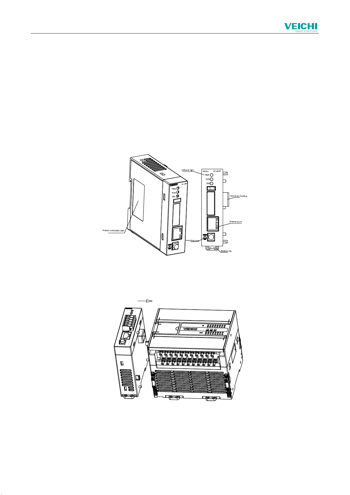
2. Check whether the VC-eNET expansion interface is securely inserted into the expansion interface.
3. Check the application to ensure that the correct operating method and parameter range are selected in the application.
5. Set the VC main module to RUN state.
6.2 Troubleshooting
If VC-eNET does not operate normally, please check the following items.
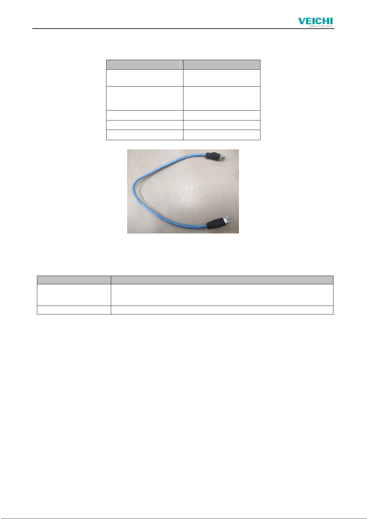
●Check the communication wiring
Confirm that the wiring is correct, refer to 1.3 Cable Specifications;
●Check the status of the "PWR" indicator of this module
Steady on: The module is connected reliably;
Off: Module contact is abnormal;
User Notice
1. The warranty scope refers to the programmable controller body.
2. The warranty period is 18 months. If the product fails or is damaged during the warranty period under normal use, we will repair it free of charge.
3. The starting time of the warranty period is the date of manufacture and ex-factory of the product. The machine code is the only basis for judging the
warranty period. Equipment without machine code will be treated as out-of-warranty.
4. Even within the warranty period, a certain repair fee will be charged in the following cases:
Machine failure caused by not operating in accordance with the user manual;
Machine damage caused by fire, flood, abnormal voltage, etc.;
Damage caused by using the programmable controller for abnormal functions.
5. The service fee is calculated according to the actual cost. If there is another contract, the contract will be dealt with first.
6. Please be sure to keep this card and present it to the maintenance unit during the warranty period.
7. If you have any questions, you can contact the agent, or contact our company directly.
Suzhou VEICHI Electric Technology Co., Ltd.
Customer Service Center in China
address:No. 1000 Songjia Road, Wuzhong Economic and Technological
Development Zone
Tel: 0512-66171988 Fax: 0512-6617-3610
Service Hotline: 400-600-0303 Website: www.veichi.com
Data version V1.0 Archive time 2021-07-30
Copyright, all rights reserved. Contents are subject to change without
notice.
VEICHI Product warranty card
Customer
information
Unit address:
Company
name:
Contact:
Contact number:
Product
information
Product model:
Body barcode:
Agency name:
Fault
information
Repair time and content:
Repair man:
Mailing
address
Suzhou VEICHI Electric Technology Co., Ltd.
address:No. 1000 Songjia Road, Wuzhong
Economic and Technological Development Zone

5
Table of contents
Other Veichi Electric DC Drive manuals
Popular DC Drive manuals by other brands

TOPTEK
TOPTEK TOPVERT E1 Series quick start

New Japan Radio
New Japan Radio NJU6062 quick start guide

Danfoss
Danfoss VLT HVAC Basic Drive FC 101 quick guide

Lenze AC Tech
Lenze AC Tech MC3000 Series Communications guide

Eaton
Eaton PowerXL DC1 manual

ITEM
ITEM LRE 8 D25 ZU 80 R50 Notes on Use and Installation