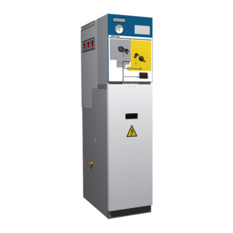
Velatia Ormazabal ormaset Instruction manual

LIB
ormaset
Kiosk-type prefabricated transformer
substation
General Instructions
IG-049-EN, version 02, 02/10/2017

In view of the constant evolution in standards and design, the characteristics of the elements contained in this manual are subject
to change without prior notice. These characteristics, as well as the availability of components, are subject to confirmation by
Ormazabal.
CAUTION!
When medium-voltage equipment is operating, certain components are live, other parts may be in movement and some may
reach high temperatures. Therefore, the use of this equipment poses electrical, mechanical and thermal risks.
In order to ensure an acceptable level of protection for people and property, and in compliance with applicable environmental
recommendations, Ormazabal designs and manufactures its products according to the principle of integrated safety, based on
the following criteria:
• Elimination of hazards wherever possible.
• Where elimination of hazards is neither technically nor economically feasible, appropriate protection functions are
incorporated in the equipment.
• Communication about remaining risks to facilitate the design of operating procedures which prevent such risks,
training for the personnel in charge of the equipment, and the use of suitable personal protective equipment.
• Use of recyclable materials and establishment of procedures for the disposal of equipment and components so
that once the end of their service lives is reached, they are duly processed in accordance, as far as possible, with the
environmental restrictions established by the competent authorities.
Consequently, the equipment to which the present manual refers complies with the requirements of section 11.2 of Standard
IEC 62271-1. It must therefore only be operated by appropriately qualified and supervised personnel, in accordance with the
requirements of standard EN 50110-1 on the safety of electrical installations and standard EN 50110-2 on activities in or near
electrical installations. Personnel must be fully familiar with the instructions and warnings contained in this manual and in other
recommendations of a more general nature which are applicable to the situation according to current legislation[1].
The above must be carefully observed, as the correct and safe operation of this equipment depends not only on its design but also
on general circumstances which are in general beyond the control and responsibility of the manufacturer. More specifically:
• The equipment must be handled and transported appropriately from the factory to the place of installation.
• All intermediate storage should occur in conditions which do not alter or damage the characteristics of the equipment
or its essential components.
• Service conditions must be compatible with the equipment rating.
• The equipment must be operated strictly in accordance with the instructions given in the manual, and the applicable
operating and safety principles must be clearly understood.
• Maintenance should be performed properly, taking into account the actual service and environmental conditions in
the place of installation.
The manufacturer declines all liability for any significant indirect damages resulting from violation of the guarantee, under any
jurisdiction, including loss of income, stoppages and costs resulting from repair or replacement of parts.
Warranty
The manufacturer guarantees this product against any defect in materials and operation during the contractual period. In the
event that defects are detected, the manufacturer may opt either to repair or replace the equipment. Improper handling of this
equipment and its repair by the user shall constitute a violation of the guarantee.
Registered Trademarks and Copyrights
All registered trademarks cited in this document are the property of their respective owners. The intellectual property of this manual
belongs to Ormazabal.
[1] For example, in Spain the “Regulation on technical conditions and guarantees for safety in high-voltage electrical installations” – Royal Decree
337/2014 is obligatory.

IG-049-EN version 02; 02/10/2017 3
General Instructions
ormaset
Kiosk-type prefabricated transformer substation
Table of contents
1. Description and main characteristics.......................4
2. Applicable standards.................................................5
3. Main components ......................................................6
3.1. Prefabricated monoblock concrete enclosure 6
3.2. Electrical equipment .........................7
3.2.1. Medium voltage switchgear..................8
3.2.2. Low voltage switchgear . . . . . . . . . . . . . . . . . . . . . .8
3.2.3. Distribution transformer .....................8
4. Normal service conditions.........................................9
5. Assigned ratings ......................................................10
5.1. Electrical characteristics .....................10
5.2. Mechanical characteristics ..................10
6. Handling ...................................................................11
6.1. Handling ormaset...........................11
6.2. Handling the roof ...........................11
7. Transport ..................................................................12
7.1. Land transport ..............................12
7.2. Sea transport ...............................12
8. Storage......................................................................13
9. Installation ...............................................................14
9.1. Receiving the equipment ...................14
9.2. Location ....................................14
9.3. Planning....................................14
9.4. Preparing the ground .......................15
9.4.1. Excavation drawings ........................15
9.4.2. Safety recommendations....................15
9.4.3. Levelling process............................16
9.5. Access point for medium voltage and low
voltage cables ..............................17
9.6. Earth connection ...........................17
9.6.1. Protective earthing circuit (metallic parts)....17
9.6.2. Operational earthing circuit (neutral) ........18
9.6.3. Exterior earthing circuit .....................18
10. Operations sequence...............................................19
10.1. Opening and closing the access doors .......19
10.2. Connecting the generator set before zero
switching ...................................20
10.3. Commissioning . . . . . . . . . . . . . . . . . . . . . . . . . . . . .21
11. Maintenance.............................................................22
11.1. Medium voltage switchgear.................22
11.2. Replacing the switchgear ...................22
12. Accessories included in the supply.........................24
13. Environmental information ....................................25
13.1. Recyclability ................................25

IG-049-EN version 02; 02/10/2017
4
Description and main characteristics General Instructions
ormaset
Kiosk-type prefabricated transformer substation
1. Description and main characteristics
ormaset is an Ormazabal transformer substation which
is prefabricated, compact, half-buried and with external
operation, designed in accordance with Standard IEC
62271-202 for use in public electrical distribution networks
of up to 36 kV.

IG-049-EN version 02; 02/10/2017 5
General Instructions
ormaset
Kiosk-type prefabricated transformer substation
Applicable standards
2. Applicable standards
ormaset meets the following standards and specications:
Rules and specications
Standard /
specication Description
IEC 62271-1 Common specications for high voltage switchgear standards.
IEC 62271-202 High voltage/low voltage prefabricated transformer substations.
IEC 60076 Power transformers
IEC 61439-1 Low voltage switchgear. General rules.
IEC 61439-5 Low voltage switchgear. Switchgear for public distribution networks.
IEC 60529 IP ratings for enclosures.
Table 2.1. Applicable standards

IG-049-EN version 02; 02/10/2017
6
Main components General Instructions
ormaset
Kiosk-type prefabricated transformer substation
3. Main components
The ormaset transformer substation comprises the
following main components:
• Prefabricated concrete enclosure.
• Electrical equipment
3.1. Prefabricated monoblock concrete enclosure
The prefabricated enclosure is made up of the following
elements:
1Enclosure
2Removable roof
3Compartments
3.1 Medium voltage switchgear
3.2 Distribution transformer
3.3 Low voltage switchgear
4Access doors 4.1 Medium voltage area
4.2 Low voltage area and transformer
5Ventilation grilles 5.1 Inlet grille
5.2 Outlet grille
6Cable accesses
6.1 Pre-punched holes measuring 150 mm in diameter for medium voltage
cable input/output
6.2 Pre-punched holes measuring 110 mm in diameter for low voltage
cables
7Earth cable access (holes measuring 20 mm in diameter)
8Dielectric liquid collection pit
9Earthing circuits
9.1 Protective earthing circuit (metallic parts)
9.2 Operational earthing circuit (neutral)
9.3 Roof earth connector braided cable
10 Hole for low voltage auxiliary supply
11 Cable support for anchoring the power transformer supply cables
12 Lighting and auxiliary services
13 Document holder with information regarding ormaset
Figure 3.1. Detail of main components of ormaset

IG-049-EN version 02; 02/10/2017 7
General Instructions
ormaset
Kiosk-type prefabricated transformer substation
Main components
The ormaset enclosure consists of a concrete body with
access doors and metallic ventilations. It has three separate
compartments used for housing the following electrical
equipment:
1. Medium voltage functions, with independent access.
2. Transformer, accessible through the low voltage
compartment.
3. Low voltage boards, with independent access.
The three compartments can be accessed through the two
independent accesses with double-leaf metallic doors,
which in their open positions are set at 90º or 180º.
The four-slope arrangement of the roof prevents water
from accumulating on it.
If it is necessary to replace part of the electrical equipment
housed inside ormaset, the roof has four embedded nuts
for installing four M20 hoisting eyebolts, which allow using
a crane for handling the roof.
3.2. Electrical equipment
The electrical equipment is located inside and anchored to
the enclosure, which can house the following elements:
• Ormazabal's cgmcosmos (24 kV) or cgm.3 (36 kV)
medium voltage switchgear unit with full SF6gas
insulation allows maximum congurations of:
- 3L1P for the 24 kV series (3 feeder functions and 1
fuse protection function).
- 2L1P for the 36 kV series (2 feeder functions and 1
fuse protection function).
• Oil-lled medium voltage/low voltage distribution
transformer unit with rated power of 1000 kVA and
36 kVA. It has natural ventilation, in accordance with
standard EN 60076 and is equipped with medium
voltage plug-in terminals.
• Low voltage switchgear:
- AC-4 type switchboard, specically built for ormaset.
- AM-4 type switchboard, specically built for
ormaset.
• Medium voltage interconnections using plug-in
terminals and low voltage interconnections direct by
cable.
The maximum possible congurations for 24 kV and 36 kV
are listed below, allowing other diagrams with fewer
medium voltage functional units and/or low voltage
switchboards:
Up to 24 kV
MV 3L1P
LVB AC4 + AM4
Transformer ≤1000 kVA
Up to 36 kV
MV 2L1P
LVB AC4 + AM4
Transformer ≤1000 kVA
Figure 3.2. Detail of maximum conguration single-wire diagrams
for 24 kV and 36 kV

IG-049-EN version 02; 02/10/2017
8
Main components General Instructions
ormaset
Kiosk-type prefabricated transformer substation
3.2.1. Medium voltage switchgear
ormaset can house medium voltage functions of
Ormazabal's cgmcosmos (24 kV) or cgm.3 (36 kV) systems
with SF6gas insulation.
The medium voltage unit is comprised of the following
independent compartments:
1SF6tank
2Driving mechanism compartment
3Base 3a Cable compartment
3b Gas relief compartment
Figure 3.3. Detail of conguration of Ormazabal’s cgmcosmos.2lp for
24 kV
3.2.2. Low voltage switchgear
The low voltage area includes space for two AC4 and AM4
type switchboards specic for ormaset, with four outputs
per module.
1Insulated enclosure
2Three-pole vertical closed bases size 02 up to 400 A
3Low voltage switchboard, type AM4, for ormaset
4Low voltage switchboard, type AC4, for ormaset
5Control and protection functional unit
Figure 3.4. Detail of low voltage switchboards for the ormaset enclosure
3.2.3. Distribution transformer
ormaset can house three-phase distribution transformers
in accordance with standard IEC 60076, up to 1000 kVA.
The medium voltage transformer connection is carried out
using shielded plug-in terminals.
Figure 3.5. Transformer detail

IG-049-EN version 02; 02/10/2017 9
General Instructions
ormaset
Kiosk-type prefabricated transformer substation
Normal service conditions
4. Normal service conditions
ormaset is designed to operate under normal service
conditions in accordance with Standard IEC 62271-1:
Installation Outdoor
Maximum environmental temperature + 40 ºC (a)
Minimum environmental temperature - 10 ºC
Maximum mean environmental temperature, measured over a 24-hour period + 35 ºC
Maximum mean relative humidity, measured over a 24-hour period < 95 %
Maximum mean relative humidity, measured over a 1-month period < 90 %
Maximum mean vapour pressure, measured over a 24-hour period 2.2 kPa
Maximum mean vapour pressure, measured over a 1-month period 1.8 kPa
Maximum height above sea level 1000 m (b)
Solar radiation 1000 W/m2
Pollution due to corrosive and/or inammable gases Level II (medium)
Vibrations due to seismic movements or by external causes Negligible
Wind speed < 34 m/s
Table 4.1. Normal service conditions
(a)For special operating conditions (maximum environmental temperature greater than + 40ºC), please ask Ormazabal
(b)For higher altitudes, please ask Ormazabal

IG-049-EN version 02; 02/10/2017
10
Assigned ratings General Instructions
ormaset
Kiosk-type prefabricated transformer substation
5. Assigned ratings
5.1. Electrical characteristics
Electrical characteristics
Rated voltage of medium voltage circuits kV up to 36
Number of phases --- 3
Rated frequency Hz 50/60
Rated power kVA up to 1000
Table 5.1. Electrical characteristics
5.2. Mechanical characteristics
The dimensions and weights of ormaset are the following:
Figure 5.1. Detail of ormaset enclosure dimensions. Front view
Figure 5.2. Detail of ormaset enclosure dimensions. Rear view
Dimensions in mm. Weight of the ormaset transformer substation without
the transformer: 7300 kg.

IG-049-EN version 02; 02/10/2017 11
General Instructions
ormaset
Kiosk-type prefabricated transformer substation
Handling
6. Handling
6.1. Handling ormaset
For correct handing of ormaset, you must ensure the
following materials are available:
• 25 t Lifting beam.
• 2 round slings WLL 10 T. E 300 / 6.
• 4 Flat slings CS-6000 Length: 3.1 m.
The following sequence must be followed for handling the
ormaset:
1. According to the handling distances required for the
unloading and placement of ormaset, select the
required crane, following the approximate values listed
in the following table:
Weight
(t)
Crane rated power [t]*
20 25 30 35 40 45
7.3 6 m 8 m 10 m 12 m 14 m 15 m
* The rated power is at a distance of 3 m.
Table 6.1. Crane rated power
2. Attach the four at sling hooks to the ormaset DEHA
couplings, as shown in the gure:
Figure 6.1. Detail of proper coupling to ormaset
3. Place the end of the lifting beam with holes on the side
of the air inlet grille.
4. Install the round transverse balancing slings, taking into
account that one of them is placed in the hole marked
with the number "1".
1Two round slings. Length: 2 m.
2Four at slings. Length: 3.1 m.
Figure 6.2. Detail of handling using a lifting beam for balancing
the ormaset
Weight of the ormaset transformer substation without
the transformer: 7300 kg.
Dimensions in mm.
6.2. Handling the roof
If the ormaset roof must be handled in order to install
or replace electrical equipment, carry this process out in
accordance with the sequence indicated in the rst four
paragraphs of section 11.2 of this General Instructions
document, "Replacing electrical equipment".

IG-049-EN version 02; 02/10/2017
12
Transport General Instructions
ormaset
Kiosk-type prefabricated transformer substation
7. Transport
7.1. Land transport
Transport of ormaset should be carried out using a truck
(maximum height of the platform: 1.5 m), following the
sequence below:
1. Position the ormaset on four boards measuring
2000 x 150 x 20 mm, distributed evenly throughout the
width of the truck.
2. The lashing must be carried out using ropes. These
ropes are hooked to the DEHA anchors that ormaset
is equipped with, in order to ensure its stability during
transport.
3. In order to prevent movements of the roof relative to
the body during transport, two 10 m slings must be
placed crosswise and tightened with a ratchet, as can
be seen in the gure.
1Two ratchet-tensioned transverse slings, length: 10 m
2Rope hooked to DEHA
3Four 2000 x 150 x 20 mm boards
Figure 7.1. Detail of ormaset land transport
7.2. Sea transport
Transport to the place of embarkation should be carried
out using a truck (maximum height of the platform: 1.5 m)
using a at rack open container. The dimensions listed in
the gure must be observed and the following sequence
must be followed:
1. Position the ormaset on four boards measuring 2000 x
150 x 20 mm, distributed evenly throughout the width
of the truck.
2. Once ormaset is positioned inside the container, attach
four 100 x 100 x 10 mm and 100 mm long squares, one
at each corner of the ormaset enclosure. They must be
welded to the oor of the container in order to prevent
any movement during transport.
3. In order to prevent movements of the roof relative to
the body during transport, two 10 m slings must be
placed crosswise and tightened with a ratchet, as can
be seen in the gure.
1Open rack container
2Two ratchet-tensioned transverse slings, length: 10 m
3Four squares in the corners, 100 x 100 x 10, length 100 mm
4Four 2000 x 150 x 20 mm boards
Figure 7.2. Detail of ormaset on a truck, for sea transport

IG-049-EN version 02; 02/10/2017 13
General Instructions
ormaset
Kiosk-type prefabricated transformer substation
Storage
8. Storage
Storage of ormaset must be carried out so as to avoid any
rainfall or sunlight falling directly on the internal electrical
equipment. Store in a non-aggressive environment.
The recommended conditions are as follows:
1. Environmental air temperature should not exceed
55 ºC and its mean value, measured in a period of
24 hours, should not exceed 35 ºC.
2. The environmental air temperature should not drop
below - 15 ºC.
3. The switchgear must be protected from direct solar
radiation.
4. Maximum altitude is 1000 m.
5. The environmental air must not have any signicant
contamination from dust, smoke, corrosive and/or
inammable gases, vapours or salt.
6. The switchgear must be protected from the rain, and
the humidity conditions should be as follows:
a. The mean relative humidity value, measured over a
period of 24 hours, must not exceed 95%.
b. The mean water steam pressure value, measured
over a period of 24 hours, must not exceed 2.2 kPa.
c. The mean relative humidity value, measured over a
period of one month, must not exceed 90%.
d. The mean water steam pressure value, measured
over a period of one month, must not exceed
1.8 kPa.
7. During transport, vibrations caused by external factors
or seismic movements must be insignicant.
Any other conditions must be notied beforehand,
since the equipment must be factory-adjusted to the
environmental pressure at the nal destination or
during transport. If this is not the case, the manometer
needle of the medium voltage switchgear may indicate
an incorrect value, even if the equipment's internal gas
pressure is correct.
Figure 8.1. Storage conditions

IG-049-EN version 02; 02/10/2017
14
Installation General Instructions
ormaset
Kiosk-type prefabricated transformer substation
9. Installation
When installing the ormaset at its location, it is essential
to follow current legislation on installations and electrical
networks, laws on occupational safety, local regulations and
the specications of the utility company. The instructions
included in this document must be followed during
electrical installation.
The site should be visited in advance to check if
vehicles can have access and if there is adequate
space for the unloading operations, taking into
account the distances to overhead lines, slopes, etc.
9.1. Receiving the equipment
Upon receipt of the unit, carefully check:
1. The general condition of the assembly.
2. Absence of bangs or breakage, especially at the
connection points to other items or close to the DEHA
couplings.
3. The state of the paintwork, checking for the absence of
chipping, scratches, etc.
4. Presence of other accessories. If damage or absences
are observed, immediately inform the transport agent
and Ormazabal.
9.2. Location
The site location should be precisely dened, indicating
the alignment levels and the heights of the reference
points, such as: roads, kerbs, milestones, pavilions, fences,
electricity pylons, etc.
Incorrect levelling may cause the base of the tank or
the body to break.
9.3. Planning
On the location sketch or drawing, it is advisable to mark
out the spaces available for the crane and the transport
truck.
The existence of any circumstance or object that could
impede or obstruct the smooth operation of the installation
must be indicated (posts, cables, ditches, walls, pipelines,
etc.), marking their positions on the drawing with the
corresponding measurements.

IG-049-EN version 02; 02/10/2017 15
General Instructions
ormaset
Kiosk-type prefabricated transformer substation
Installation
9.4. Preparing the ground
9.4.1. Excavation drawings
For the installation of ormaset, an excavation is required[1],
with the dimensions recommended in the following table:
Excavation dimensions [mm]
Length 5675
Width 4270
Depth 950
Table 9.1. Excavation dimensions
1Perimeter pavement
2Levelling area
Figure 9.1. Detail of ormaset excavation dimensions
Please enquire if installing on slopes
Dimensions in mm.
9.4.2. Safety recommendations
All actions and procedures must be carried out in
accordance with the General Safety Plan. There must be a
person designated as the Prevention Resource throughout
the duration of the activity on site.
The minimum health and safety requirements for
construction work should be considered when preparing
the ground. Among others:
• Before beginning to open, carry out a preliminary study
of the ground to know its stability and the possible
existence of conduits.
• Avoid accumulating excavated material and equipment
next to the edge of the excavation, taking the necessary
precautions to prevent the walls from caving in and
materials falling inside.
• In general, keep a 3 m area around the excavation free of
materials and vehicle trac.
• In the case of rain and puddles, carefully inspect the
excavation with qualied technicians before resuming
the work. Carry out immediate pumping out of water
that may be present inside the excavation in order to
prevent the stability of the slope from being altered.
• Engine-driven machines that generate gases such
as carbon monoxide must not be placed inside the
excavation unless adequate equipment is used to
extract the gases.
• The operators that work inside the excavation must be
properly trained and informed and must use a safety hat
as well as the appropriate protective clothing for each
specic hazard.
[1] See section 9.6.3 of this General Instructions manual, "External earthing circuit"

IG-049-EN version 02; 02/10/2017
16
Installation General Instructions
ormaset
Kiosk-type prefabricated transformer substation
9.4.3. Levelling process
In order to properly install the ormaset enclosure, it is
important to take ground levelling into account, since this
decisively aects the stability of the equipment.
The following tools must be used for carrying out the
levelling:
• Spirit level.
• Levelling tools.
• Levelling board.
Once the excavation has been carried out, a layer of sand
of approximately 100 mm thick must be laid, then levelled
and compacted.
The existence of special ground conditions may require
modifying the ormaset installation regarding what has
been previously stated.
Non-compacted ground
Prepare a foundation suitable for the ground conditions,
and it may even be necessary to construct a reinforced
concrete bed to distribute the load over a wider surface.
Levelling with sand must then be carried out.
Sloping ground
The excavation should be carried out in such a way that the
base platform is on a hard area, as shown in the gure.
In these cases, it is recommended that rainwater from
the higher ground be channelled, to avoid it washing the
ground away from under the ormaset.
1Minimum: 1000 mm
2Level 0
Figure 9.2. Detail of installation on sloping grounds
Ground with a high water table
In those cases where the water table is above the location
of the ormaset foundation plate, proceed as indicated in
the gure:
1Level 0
2Water table
Figure 9.3. Detail of installation on ground with a high water table
Ground at risk of flooding
On ground where a risk of ooding exists, the ormaset
foundation layer must be placed above the predicted
ooding level, as indicated in the gure.
In cases where the possibility exists for the layer of
foundation sand to be washed away, it is recommended
that a cement - sand mixture be used for this purpose.
145º Slope
2Predicted Flood Level
3Level 0
Figure 9.4. Detail of installation on ground with risk of ooding
Dimensions in mm.

IG-049-EN version 02; 02/10/2017 17
General Instructions
ormaset
Kiosk-type prefabricated transformer substation
Installation
9.5. Access point for medium voltage and low voltage cables
ormaset has holes pre-punched for the medium voltage
and low voltage cables and the external earthing circuit.
For the medium voltage cable input and output, ormaset
has three pre-punched holes measuring 150 mm in
diameter, located in the buried part of the enclosure, in the
area where the medium voltage functions are housed.
For the low voltage cable output, ormaset has eight pre-
punched holes measuring 110 mm in diameter, located in
the buried part of the enclosure, where the low voltage
boards are housed.
The closure of these holes is a concrete shell measuring
about 10 mm thick.
Drilling of holes for feeding cables through them
1. Break the hole closure by striking it with a hammer.
Tool: hammer
2. Seal the used holes to prevent water from entering
using any type of quality exible sealant.
Tool: Quality exible sealant
1Access for low voltage cables
2Access for medium voltage cables
Figure 9.5. Detail of ormaset cable access in enclosure
9.6. Earth connection
ormaset has two internal earthing circuits to facilitate the
connection of the dierent elements to the earthing circuit
external to the transformer substation.
• Protective earthing circuit (metallic parts).
• Operational earthing circuit (neutral).
9.6.1. Protective earthing circuit (metallic parts)
The protective earthing circuit (metallic parts) includes
the earthing of the enclosures of the dierent electrical
equipment as well as the concrete enclosure reinforcement:
1. Medium voltage functions.
2. Transformer.
3. Low voltage boards and other metallic elements
present in the installation.
4. Concrete enclosure reinforcement (body and roof are
interconnected using a copper wire).
5. Metallic parts.
The earthing atbar is connected to the protective switch
box (metallic parts) that is located to the right of ormaset's
low voltage access door, using a 50 mm2bare copper
connector. This box is connected to the external earthing
circuit. Access for the external earthing cables is made using
two pre-punched holes measuring 20 mm in diameter.
Figure 9.6. Detail of protective earthing connection (metallic parts).

IG-049-EN version 02; 02/10/2017
18
Installation General Instructions
ormaset
Kiosk-type prefabricated transformer substation
9.6.2. Operational earthing circuit (neutral)
The operational earthing circuit (neutral) connects the
neutral busbar of the low voltage distribution board to the
operational earthing switch box, which is located to the left
of the low voltage access door. This connection is made by
means of insulated 0.6/1 kV copper or 50 mm2aluminium
cable.
The low voltage board zero-sequence bar is not
connected to the protective earthing atbar (metallic
parts).
Figure 9.7. Detail of the switch box for connecting the neutral
9.6.3. Exterior earthing circuit
The installer or nal user must provide suitable safety
measures in order to avoid dangerous touch and step
voltage.
The installation project must include the section for
implementation of the earthing installation, along with
justication of its sizing.
Complementary Technical Instruction ITC-RAT 13, on
earthing installations, of the Regulation on technical
conditions and safety guarantees in high voltage electrical
installations (Royal Decree 337/2014) sets out the
requirements for this type of installation.
The conductors' braided wire cross-section, the terminals'
contact surface and tightening torques will be suitable
for a fault current delimited by network protections. It is
recommended that an external protective earthing circuit
of bare copper wire be used with a minimum cross-section
of 50 mm2.
Whenever it is not feasible to maintain the touch and
step voltages within the limits set out in Complementary
Technical Instruction ITC-RAT 13 of the Regulation on
technical conditions and safety guarantees in high voltage
electrical facilities (Royal Decree 337/2014), the owner of
the facility must implement at least one of the additional
safety measures envisaged in this instruction, in order to
reduce the risks to people and property.

IG-049-EN version 02; 02/10/2017 19
General Instructions
ormaset
Kiosk-type prefabricated transformer substation
Operations sequence
10. Operations sequence
10.1. Opening and closing the access doors
Proceed as follows to open the access doors in both the
medium voltage and the low voltage area and transformer:
1. Open the right door by acting on the lock.
Figure 10.1. Right door opening
2. Release the bolts of the left-hand door to open it.
Figure 10.2. Release the bolts of the left-hand door.
3. The doors have an interlocking system at 90º and
180º. To open the door at 180º, pull the rod upwards
to release it, and open the door completely until it is
interlocked at 180º.
Figure 10.3. Door interlocking mechanism
To close the doors, proceed in reverse order, making sure
to release the rod before moving the doors from their
interlocked at 90º or 180º open position.

IG-049-EN version 02; 02/10/2017
20
Operations sequence General Instructions
ormaset
Kiosk-type prefabricated transformer substation
10.2. Connecting the generator set before zero switching
ormaset has an auxiliary input measuring 140 mm in
diameter that allows for a low voltage auxiliary supply.
When not in use, this auxiliary input has a lid that maintains
the IP 23D rating, in accordance with IEC 60529. It can only
be removed from the inside of the concrete enclosure.
Working in the vicinity of live voltage. Operation which
can only be carried out by specialist personnel, in
accordance with the utility company's procedures and
with rules on electrical safety.
Figure 10.4. Detail of input for auxiliary supply in an ormaset enclosure
The cables from the generator set should run to inside the
ormaset prefabricated enclosure through the hole tted
for this purpose. Proceed as follows to open the hole.
1. Loosen the wing nut from inside the prefabricated
enclosure.
Figure 10.5. Loosen the wing nut
2. Loosen the wing nut and the clamp. Set aside both
parts.
Figure 10.6. Loosen the wing nut and the clamp
3. Open the hole by pushing the cover towards the outside
of the enclosure. Set aside the cover along with the
wing nut and the clamp, in order to close the hole when
auxiliary supply with the generator set is complete.
Figure 10.7. Push the cover
4. Insert the generator set cables through the open hole.
The power cable connection from the auxiliary unit to
the low voltage distribution board will only be made
once the opening of the medium voltage cubicle's
switch and the absence of current (momentary
interruption of service) have been checked.
Table of contents
Other Velatia Transformer manuals