3
ÍndexOperation instructions
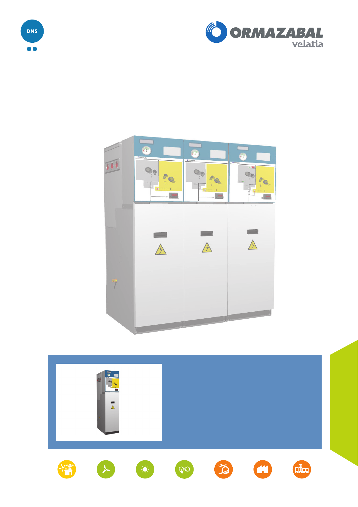
cgm.3 ENA type
IG-235-EN version 02
ÍNDEX
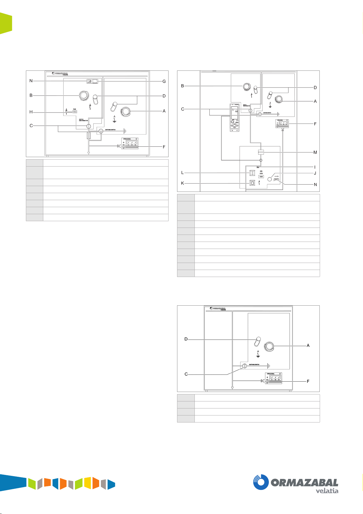
1 Description and main characteristics 4
1.1 Switchgear elements . . . . . . . . . . . . . . . . . . . . 4
1.1.1 Voltage presence indicator . . . . . . . . . . . . . . . 7
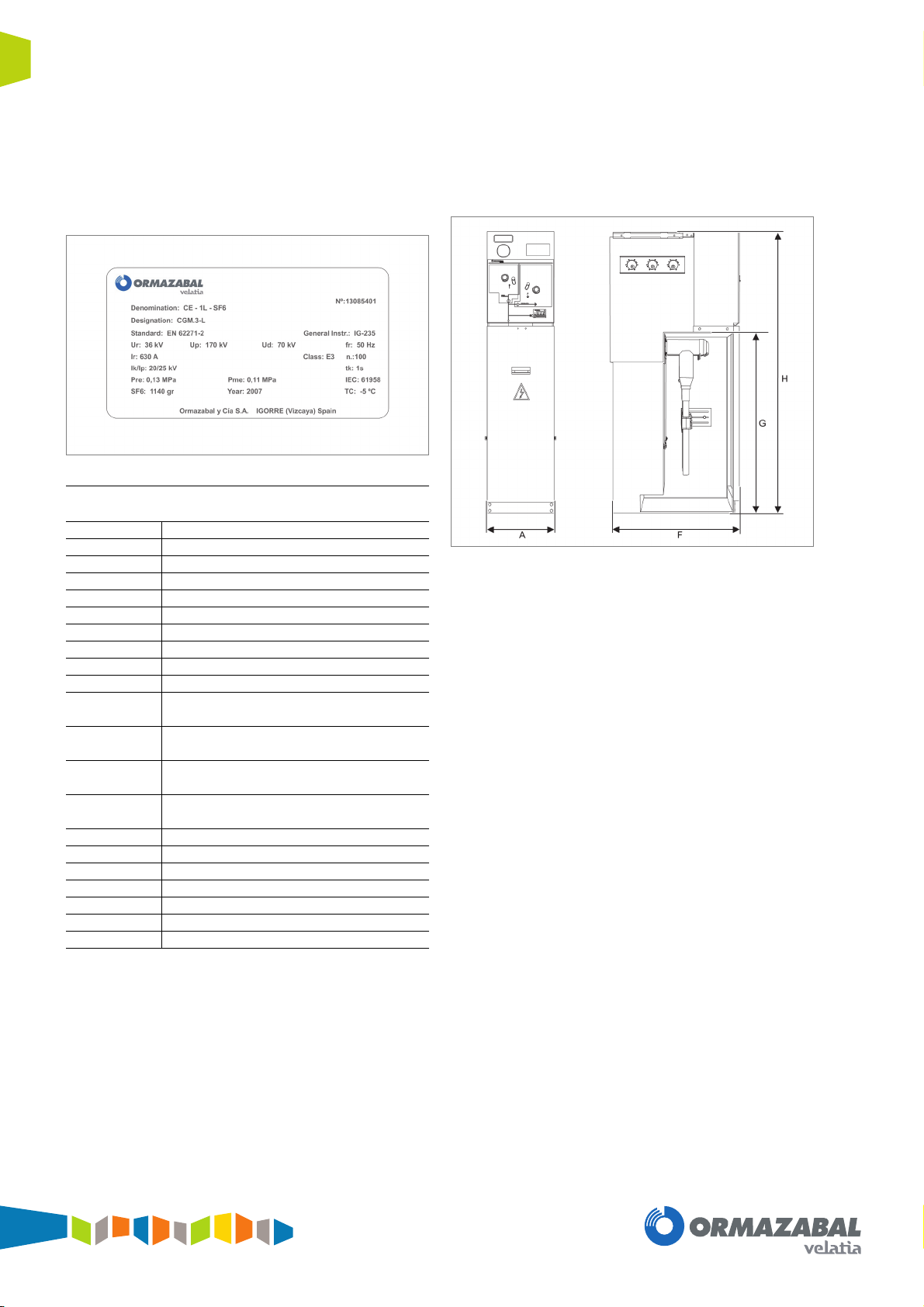
1.1.2 Name plate . . . . . . . . . . . . . . . . . . . . . . . . . . . 8
1.2 Mechanical characteristics . . . . . . . . . . . . . . . 8
2 Recommended sequence of operations 10
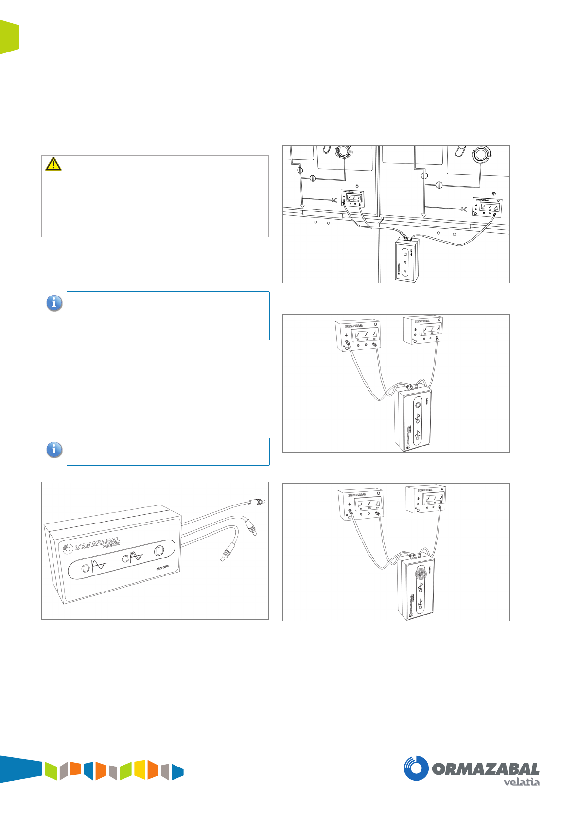
2.1 Checking voltage presence and
phase balance . . . . . . . . . . . . . . . . . . . . . . . . 10
2.1.1 ekor.spc phase comparator . . . . . . . . . . . . . . 10
2.2 Mechanism operating handles . . . . . . . . . . . 11
2.2.1 Switch - disconnector driving
mechanism handle (B) . . . . . . . . . . . . . . . . . 11
2.2.2 Spring charging handle for circuit
breaker driving mechanisms . . . . . . . . . . . . . 11
2.3 cgm.3-l switchgear . . . . . . . . . . . . . . . . . . . . 12
2.3.1 Opening operation from
the earthing position . . . . . . . . . . . . . . . . . . . 12
2.3.2 Switch closing operation from
the open position . . . . . . . . . . . . . . . . . . . . . . 12
2.3.3 Opening operation from the switch -
disconnector closed position . . . . . . . . . . . . . 12
2.3.4 Earthing operation from the open position . . 12
2.3.5 Cable test . . . . . . . . . . . . . . . . . . . . . . . . . . . 13
2.4 cgm.3-p switchgear . . . . . . . . . . . . . . . . . . . . 13
2.4.1 Opening operation from
the earthing position . . . . . . . . . . . . . . . . . . . 13
2.4.2 Switch - disconnector closing operation
from the open position (using the BR-A
driving mechanism) . . . . . . . . . . . . . . . . . . . . 13
2.4.3 Opening operation from the switch -
disconnector closed position . . . . . . . . . . . . . 13
2.4.4 Earthing operation from the open position . . 13
2.4.5 Selection of recommended fuses . . . . . . . . . 14
2.4.6 Fuse replacement sequence . . . . . . . . . . . . . 15
2.5 cgm.3-rb switchgear with earthing . . . . . . . . . 17
2.5.1 Opening operation from
the earthing position . . . . . . . . . . . . . . . . . . . 17
2.5.2 Earthing operation from
the open position . . . . . . . . . . . . . . . . . . . . . . 17
2.6 cgm.3-v switchgear with driving mechanism
A(M)V-EF and RA(M)V-EF (3G) . . . . . . . . . . 17
2.6.1 Opening operation from
the earthing position . . . . . . . . . . . . . . . . . . . 17
2.6.2 Closing operation from the open position . . . 18
2.6.3 Opening operation from
the closed position . . . . . . . . . . . . . . . . . . . . 19
2.6.4 Earthing operation from the open position . . 20
2.7 cgm.3-v switchgear with driving
mechanism A(M)V and RA(M)V (3G) . . . . . . 21
2.7.1 Opening operation from
the earthing position . . . . . . . . . . . . . . . . . . . 21
2.7.2 Closing operation from the open position . . . 22
2.7.3 Opening operation from
the closed position . . . . . . . . . . . . . . . . . . . . 23
2.7.4 Earthing operation from the open position . . 24
3 Safety locking facilities and
interlocking 26
3.1 Mechanical interlocking . . . . . . . . . . . . . . . . . 26
3.2 Safety locking facilities . . . . . . . . . . . . . . . . .26
3.2.1 Locking with a padlock . . . . . . . . . . . . . . . . .26
3.2.2 Locking with a key lock (optional) . . . . . . . . . 26
4 Maintenance 27
4.1 Voltage presence indicator test . . . . . . . . . . . 27
4.2 Specific maintenance for the
cgm.3-v switchgear . . . . . . . . . . . . . . . . . . . .27
5 Additional information 28
5.1 Current transformers arrangements . . . . . . . 28
5.2 Spares and accessories . . . . . . . . . . . . . . . . 28
5.3 Environmental information . . . . . . . . . . . . . . . 29
The instructions for the transport, storage and
installation of the cgm.3 ENA type switchgears are
included in the Ormazabal's MO-091 document.