manuals.online logo
Brands
  1. Home
  2. •
  3. Brands
  4. •
  5. Velkase
  6. •
  7. Computer Accessories
  8. •
  9. Velkase Velka 3 User manual

Velkase Velka 3 User manual

Other manuals for Velka 3

2

Other Velkase Computer Accessories manuals

Velkase Velka 7 User manual

Velkase

Velkase Velka 7 User manual

Velkase VELKA 5 User manual

Velkase

Velkase VELKA 5 User manual

Popular Computer Accessories manuals by other brands

Netstor NA255A user manual

Netstor

Netstor NA255A user manual

perixx PERIDUO-610 user manual

perixx

perixx PERIDUO-610 user manual

Cherry PURE JD-0100 operating manual

Cherry

Cherry PURE JD-0100 operating manual

Cool-Icam DICK II user manual

Cool-Icam

Cool-Icam DICK II user manual

Motorola ATRIX user guide

Motorola

Motorola ATRIX user guide

HP USB Media Docking Station specification

HP

HP USB Media Docking Station specification

Cherry B.UNLIMITED 3.0 user manual

Cherry

Cherry B.UNLIMITED 3.0 user manual

Bartec TC 7 Series user guide

Bartec

Bartec TC 7 Series user guide

Philips SPC3540 Specifications

Philips

Philips SPC3540 Specifications

Logitech mk220 user manual

Logitech

Logitech mk220 user manual

Vivo MOUNT-KB05-4DW instruction manual

Vivo

Vivo MOUNT-KB05-4DW instruction manual

SilverStone LC02 manual

SilverStone

SilverStone LC02 manual

Flexispot ML2B installation guide

Flexispot

Flexispot ML2B installation guide

Hamlet UNIVERSAL COVER 101 KBT2 user manual

Hamlet

Hamlet UNIVERSAL COVER 101 KBT2 user manual

Adam Equipment RS-485 manual 

Adam Equipment

Adam Equipment RS-485 manual 

Sven Base 305 сombo instructions

Sven

Sven Base 305 сombo instructions

Hama 108310 Operating	 instruction

Hama

Hama 108310 Operating instruction

SpeechWare FlexyMike FMK03 user manual

SpeechWare

SpeechWare FlexyMike FMK03 user manual

manuals.online logo
manuals.online logoBrands
  • About & Mission
  • Contact us
  • Privacy Policy
  • Terms and Conditions

Copyright 2025 Manuals.Online. All Rights Reserved.

Velkase Velka 3 rev 2.0 user manual (short version)
Download the detailed and most up-to-date version of the user manual at https://www.velkase.com/downloads
Specification Hardware compatibility
Dimensions
(L x W x H)
189 x 96 x 218 mm
Weight
1.5 kg
Materials and finish
5 mm aluminum front panel
1.2 mm galvanized steel and stainless
steel body
1.0 mm galvanized steel side panels
I/O
Rear: Motherboard, graphics
Security
Kensington Lock Slot
PCIe riser
PCIe 3.0 x16
Test all of your components before assembling a system in the case.
1. Assemble the computer with the graphics card plugged directly into the motherboard, test for functionality
2. In BIOS, set PCIe speed / compatibility mode to gen 3, test for functionality
3. Repeat step (1) with the PCIe riser, DisplayPort and HDMI extensions. Be gentle with these cables as they are not designed for
external use.
Disassembly
1. 2 screws on top-front and 2 screws on bottom-front to remove front panel
2. 6 screws in the front and 5 screws in the rear to remove side panels. Note: the 3 upper screws in the rear are secured by separate nuts.
Hold the nut to remove each screw.
3. 2 screws on the left and 2 screws on the right to remove struts
4. 2 screws in the back and 2 screws on the bottom to remove motherboard tray
Assembly
Motherboard
Mini ITX
170 x 170 mm
Power supply
Flex ATX (150 mm)
CPU cooler
37 mm
Graphics card
(L x W x H)
Maximum clearance, including
cables. Cables require 16 mm if not
recessed into the board.
175 x 43 x 148 mm
178 x 40 x 148 mm
Memory
42 mm
Storage
1x 2.5” HDD or SSD (7.0 mm thick)
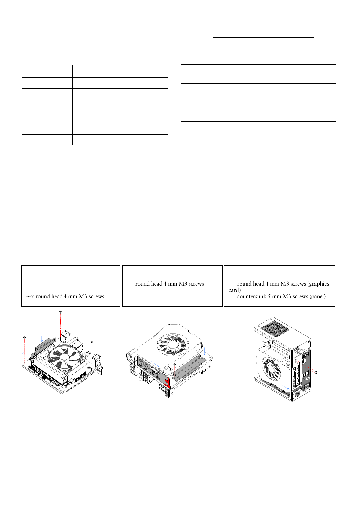
-Install CPU, cooler, memory, and M.2
drive onto the motherboard
-Attach motherboard to the tray and plug
in the PCIe riser
-Screw in the PCIe riser on the opposite
side and connect the graphics card.
-2x
-Screw in the PCIe riser on the opposite side
and connect the graphics card.
-2x
-2x
-Power button must be plugged in
-Side panels have 3 positions. Flush mount: outer-
most positions for top and bottom screws and the
middle position for the middle screw
-For quieter operation, use other mounting holes
-6x countersunk 5 mm M3 screws (front)
-3x round head 4 mm M3 screws, 2x 6-32 screw (rear)
-Slide in front panel while inserting the button’s
cable into the case. Screw in on top and bottom
-Reposition the brackets behind the front panel
for a more loose fit
-Stick on the included adhesive rubber pads
-4x countersunk 5 mm M3 screws
-Temporarily remove bottom bracket to install
button
-Use the hex nut to fix the button in place, then
reinstall the bottom bracket
-Consult your motherboard manual for the front
panel header pin layout. Plug the power button
wires into the corresponding motherboard pins
-Screw in middle subassembly with all
components at the bottom and on the
left side. Only screw in the right screw
after installing the power supply.
-3x
-Slide in the power supply in the orientation
shown and only attach it to the main body with
the middle screw
-1x
-Slide in the 2.5” drive from the front
and secure it to the main body of the
case. Connect all cables after this step
-3x
-All cables must be
plugged in before this step
-Complete the frame by
installing the two struts in
the front
-4x countersunk 5 mm M3
screws