Velleman HAA9523S User manual
HAA9523S
SELF-CONTAINED DIGITAL ACCESS CONTROL KEYPAD
ONAFHANKELIJK DIGITAAL TOETSENBORD
DIGICODE NUMÉRIQUE AUTONOME
CONTROL DE ACCESO DIGITAL INDEPENDIENTE
DIGITALE UNABHÄNGIGE TASTATUR
USER MANUAL
2
GEBRUIKERSHANDLEIDING 19
MODE D’EMPLOI 35
MANUAL DEL USUARIO 51
BEDIENUNGSANLEITUNG 67

HAA9523S
v2 15/11/2013 VELLEMAN
2
USER MANUAL
1. In roduc ion & Fea ures
To all residen s of he European Union
Impor an environmen al informa ion abou his produc
This symbol on the device or the pac age indicates that disposal of the device after its lifecycle could harm
the environment.
Do not dispose of the unit (or batteries) as unsorted municipal waste; it should be ta en to a specialized
company for recycling.
This device should be returned to your distributor or to a local recycling service.
Respect the local environmental rules.
If in doub , con ac your local was e disposal au hori ies.
Than you for buying the HAA9523S! Please read the manual thoroughly before bringing this device into service. If the
device was damaged in transit, don't install or use it and contact your dealer.
The HAA9523S is a self-contained security eypad and is a reliable and cost-effective solution for residential and
commercial installations. It is compatible with virtually any electric loc ing device and can be used as a control for
security systems, automatic operators and machinery. Over 100 million combinations are possible for the user codes
(multi-user mode). Programmed data stored in the system is non-volatile. For indoor use only.
2. Connec ions (fig. 1)
THE LED INDICATORS
•RED & GREEN
The red and green LEDs are to be connected at the installer’s will.
•AUX RED / GREEN
The green LED is a status indicator at normal operation. The LED changes to steady red while the auxiliary red
LED is energized.

HAA9523S
v2 15/11/2013 VELLEMAN
3
THE TERMINAL BLOCK
•OUTPUT 1
5A dry relay contacts, recommended for door stri e controls. Normally Open (N.O.) and Normally Closed (N.C.)
outputs are available. Use N.O. output for fail-secure loc ing device and N.C. output for fail-safe loc ing device.
The relay can be programmed in start/stop (toggle) mode or timer mode from 1 to 999 seconds.
•EG IN (EGRESS INPUT)
A N.O. input terminal refers to (-) ground with the help of a N.O. button to deactivate the output 1. The egress
button is usually put inside the house near the door. More than one egress button can be connected in parallel to
the terminal. Leave this terminal open if it is not used.
•12V-24V AC/DC (POWER INPUT)
Connect to 12V-24V AC/DC power supply. The (-) supply and GND (wire 15) are the common grounding points of
the eypad system. No selection jumper is required for the full input voltage range. Connect DC power with the (+)
and (-) polarity; there is no discrimination for the AC power input.
•DOOR SENS (DOOR POSITION SENSOR INPUT)
A N.C. input terminal referring to (-) ground. With the help of a N.C. magnetic door switch, the system will monitor
the position of the door and will give the following functions:
1. Door Au o Relock
The system will immediately reloc the door after valid access has been gained before the end of the
programmed time for output 1.
2. Door Forced Open Alarm
The eypad will generate door forced-open alarm instantly if the door is forced open without a valid user entry
or egress input. The alarm will last for 60 seconds and can be stopped with user code 1 or one of the user
codes in group 1. This function is selectable via the programming options at location 801.
3. Door Propped-Up Alarm
When the door is left open longer than the allowable time. The eypad will generate door propped-up alarm
after the expiry of the preset door opening time until the door is closed again. The door opening time is
programmable from 1 to 999 seconds at location 9.
4. In erlock Con rol
The interloc control output goes to (-) while the door is open in order to give signal to disable the other
eypad in the interloc system.
THE WIRE HARNESS
NOTE: Always hold the PCB tightly and gently pull out the soc et to prevent damage of the electronic assembly of
the eypad.
•N.C. TAMPER (1-2)
N.C. contact when the eypad is secured on the box. It is open when the eypad is separated from the box.
Connect the terminal to the 24-hour zone of an alarm system if necessary.
•GREEN, RED & AUXILIARY RED LEDs (3-4), (5-6) & (7)
Three on-board LED lamps are available. They are prepared for free connections. Connect these to the remote
indicator driving terminals of your equipment such as an alarm control panel. Mind the polarity.
The green and red lamps that are independent are equipped with 1.5 Ω current limiting resistor.

HAA9523S
v2 15/11/2013 VELLEMAN
4
The anode of the auxiliary red LED is connected to the +5V internally. It turns on with the cathode (wire 7)
connected to (-) ground.
•KEYPAD ACTIVE OUTPUT OR ALARM OUTPUT (8)
An NPN transistor open collector output with max. rating of 100mA sin and 24VDC. It is selectable to give
Keypad Active Output or Alarm Output via the K or A jumper.
1. Keypad Ac ive Ou pu (KEY)
It switches to (-) ground for 10 seconds with each press of the ey. This can be used to turn on lights, CCTV
cameras or buzzer.
2. Alarm Ou pu (AL)
Switches to (-) ground when the Door Forced Open Alarm or Door Propped-Up Alarm occurs in order to trigger
the external alarm to give notification at a remote location.
•OUTPUT 2 (9-10-11)
Auxiliary relay output with 1A N.O. and N.C. dry contacts controlled by user code 2 and ideal for controlling
security systems and automatic operators. It is programmable for start/stop (toggle) operation or timing operation
from 1 to 999 seconds.
•OUTPUT 3 (12)
An NPN transistor open collector output ideal for auxiliary control functions such as security systems. This output
is programmed for start/stop (toggle) operation or timing operation from 1 to 999 seconds. It switches to (-) ground
when active and the max. rating is 100mA sin / 24VDC.
•OUTPUT 1 DISABLE (13)
A N.O. input terminal refers to (-) ground. Neither user code 1 nor egress button can activate output 1 when this
terminal is tied to (-) ground. It is prepared for cross-wired connection in an interloc application.
•INTERLOCK CONTROL OUTPUT (14)
An NPN transistor open collector output. It is off at normal condition and switches to (-) ground immediately for the
first 5 seconds after eying in a valid user code to operate output 1. Then, it will eep tying to (-) during the time
that the door position sensor is open. Use this output to control the other eypad in an interloc system to prevent
both doors from opening at the same time.
•DURESS OUTPUT (16)
An NPN open collector output. It switches to (-) ground when the duress code is entered. Use it to trigger an
alarm zone or to turn on a buzzer to notify a guard. Ic max.: 100mA sin ; Vc max.: 24VDC.
3. The Pacifier Tones & LED Indica ing Signals
The built-in buzzer and the green LED indicator in the centre give the following tones and signals for operation status:
STATUS
TONES*
LED SIGNALS
1.
In programmable mode
-
-
-
ON
2.
Successful ey entry
1 beep
1 flash
3.
Successful code entry
2 beeps
2 flashes
4.
Unsuccessful code entry
5 beeps
5 flashes
5.
DAP jumper not replaced
Continuous beeps
Continuous flashes
6.
In standby mode
-
-
-
1 flash in 2
-
seconds interval
7.
Output relay activated
1
-
second long beep
**
-
-
-
NOTE: * All pacifier tones can be enabled or disabled through programming options at location 83.
HAA9523S
v2 15/11/2013 VELLEMAN
5
** The output activation beep can be enabled or disabled through programming options at location 82.
4. Rese mas er code
If you have forgotten the master code, you can reset it. For the master code, do not use a combination that is already
ta en for a user code.
If the personal master code is forgotten, use the DAP jumper to override the forgotten code permitting direct entry
into programming mode. You are required to apply the following procedure precisely:
1. Disconnect power supply.
2. Displace the DAP jumper from OFF to ON.
3. Reconnect power supply (buzzer is activated).
4. Put the DAP jumper bac to OFF position (this done, the buzzer is de-activated).
5. The Keypad is in programming mode and ready to receive your new programming data.
6. Enter a new 4-digit master code at location 0 in case you have forgotten the old master code.
7. Enter the new programming data starting from Section B) in the summary chart shown below.
5. The Fac ory-Se Mas er Code – Impor an No e
When programming for the first time, the master code 0000 shall be used. In all cases, program a new master code
to invalidate the old master code and to ensure security.
6. Programming he Keypad – Summary Char
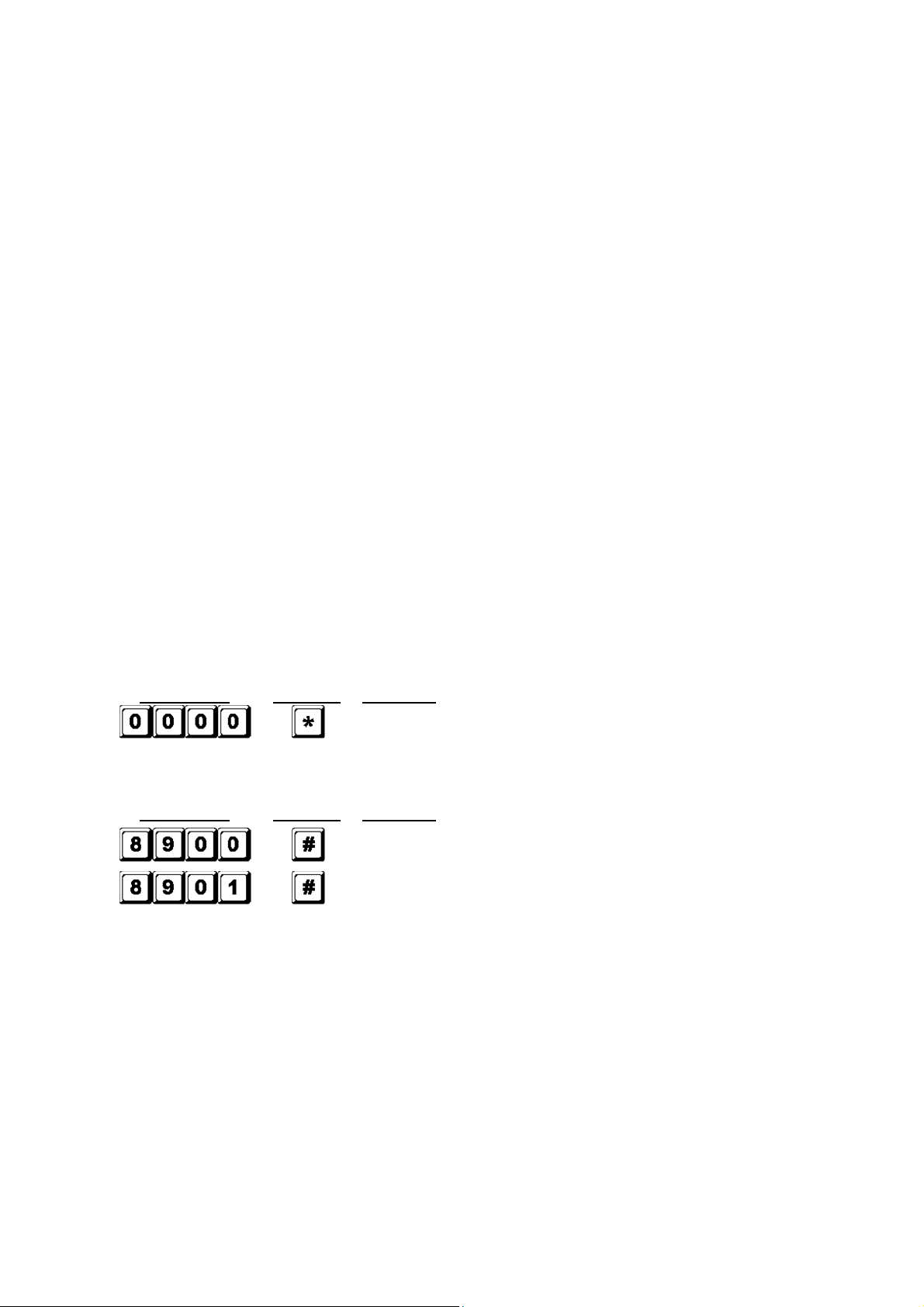
A) Use he fac ory-se mas er code en ry in programming -- When s ar ing for firs ime only
Entry of code
Validation
Comments
Enter in programming mode by factory set master code
B) Se he sys em o single or mul i-user mode and refresh he sys em – Ins aller programming
Entry of code
Validation
Comments
Set the
system to single user mode, clear all previously stored
data and refresh system
Set the system to multi
-
user mode, clear all previously stored
data and refresh system
C) Record he personal mas er code and user codes – User programming
No es: mas er code
•When programming the codes, it is recommended to program the master code before the user codes.
•If you are programming a new master code, do not use a combination that is already ta en for a user code.
•If you have forgotten the master code, you can reset it. See section 4.Reset master code)
No es: user code
•Any user code must be different from the master code.
•It is recommended to program a different code for every user.
1. Single user – Digi s may be repea ed

HAA9523S
v2 15/11/2013 VELLEMAN
6
Locations
Entry of codes
Validation
Comments
4 digits, fixed
Personal master code and super user code
4 digits, fixed
User code 1 for output 1 with duress code function
4 digits, fixed
User code 2 for output 2
4 digits, fixed
User code 3 for output 3
2. Mul i-user – Digi s may be repea ed
Locations
User number
Entry of codes
Validation
Comments
4 to 8 digits
Personal master code and super user
code
00 to 99 4 to 8 digits
100 user codes in group 1 for output 1 with
duress code function
0 to 9 4 to 8 digits
10 user codes in group 2 for output 2
0 to 9 4 to 8 digits
10 user codes in group 3 for output 3
D) Configura ion of he ou pu modes – Ins aller programming
Locations
Code duration
Validation
Comments
1 to 999s
Output 1 momentary mode from 1 to 999 seconds
Output 1 in start/stop mode (toggle)
Output 1 in start/stop mode w/ accelerated code
1 to 999s
Output 2 momentary mode from 1 to 999 seconds
Output 2 in start/stop mode (toggle)
Output 2 in start/stop mode w/ accelerated code
1 to 999s
Output 3 momentary mode from 1 to 999 seconds
Output 3 in start/stop mode (toggle)
Output 3 in start/stop mode w/ accelerated code
E) Personal safe y – Ins aller programming
Locations
No. of false entry
Validation
Comments
After 10 successive false codes, the eypad loc s
during 30 seconds
After 10 successive false codes, the duress output
switches to ground
5 to 10
Selectable after 5 to 10 successive false
codes, the
eypad loc s during 15 minutes. The eypad can be
reset to release loc ing with the master code at any
time during the loc ing period.
00
All of the above securities disappear
F) Door forced-open alarm – Ins aller programming

HAA9523S
v2 15/11/2013 VELLEMAN
7
Locations
Code of functions
Validation
Comments
Door forced-open alarm is enabled
Door forced-open alarm is disabled
G) Ou pu ac iva ion announcer – Ins aller programming
Locations
Code of functions
Validation
Comments
1
-
second
notifying beep is given to notify the person
outside to open the door when the output relay is
activated with a user code or egress button. Good for a
loc ing device without sound such as a magnetic loc .
Notifying beep disabled and replaced by 2
short
successful code entry beeps for valid user codes
H) User code en ry mode (au o or manual) – Ins aller programming
Locations
Code of functions
Validation
Comments
Auto entry code is selected. ey following the user
code is NOT required in code entry. The user code
MUST be set in the same digit length as the master
code in auto entry mode and the code length can be 4
to 8 digits long.
Manual entry mode is selected. ey following the
user code is required in code entry. The user codes
can be 4 to 8 digits long and they are not required to
be the same length as the master code.
NOTE: In single user mode, no matter the selection (auto or manual mode), the master code and the user
code MUST be set as a 4-digit number.
I) Pacifier ones (keypad acknowledgemen ones) – Ins aller programming
Locations
Code of functions
Validation
Comments
Pacifier tones available on the eypad
All pacifier tones are off.
J) Allowable ime o s ar door propped-up alarm – Ins aller programming
Locations
Code of functions
Validation
Comments
0
No propped-up alarm
1 to 999
Allowable time from 1 to 999 seconds before door
propped-up alarm starts
K) Exi programming mode
Validation
Comments
Exit programming mode and return to normal operation
7. Single User or Mul i-User Mode Selec ion
HAA9523S
v2 15/11/2013 VELLEMAN
8
The HAA9523S has been factory-set in single user mode with as master code.
Single user mode (command code: 8900)
Each output can only be operated by one user code. The user code must be 4 digits long. There are 10 000
possible code combinations. The code can be programmed directly into the user code locations 1, 2 and 3
respectively for the 3 outputs. Refer to “6. C) 1. Single user – Digi s may be repea ed” for more details. This
mode is always set with auto code entry in default. You do not need to press in user code entry. Only enter the
4-digit user code.
NOTE: The system can be set for manual code entry with programming option 0 at location 82 if necessary.
Mul i-user mode (command code: 8901)
Up to 100 individual codes will operate output 1 and 10 individual codes will operate output 2 and 3. The user
code can be 4 to 8 digits long. There are over 100 million possible code combinations. The user codes can be set
for auto or manual entry with programming options at location 82. Default mode is manual entry mode. Pressing
after code entry is required. Once the eypad is programmed in auto entry, the master code and the user
codes MUST consist of the same number of digits. Do not press after entering the user code.
Defaul values
Defaul
Commen s
Defaul
Commen s
401
Output 1 in 1
-
second
momentary
mode
811
Output relay activation beep on
501
Output 2 in 1
-
second momentary
mode
820
User code manual entry mode* (multi
-
user)
601
Output 3 in 1
-
second momentary
mode
821
User code auto entry mode* (single
user)
70
After 10 successive false
co
de
s
, the
eypad loc s during 30 seconds
831
Pacifier tones on
800
Door forced
-
open alarm disabled
90
No propped
-
up alarm
NOTE: * All default values in multi-user and single user mode are exactly the same except the user code entry
mode.
Code en ry limi a ion in mul i-user mode due o duress code
The system comes with duress function for user code 1 in single user mode and all the user codes of group 1 in
multi-user mode. The duress code is automatically set by the system by ta ing the first digit of the user code and
adding or subtracting 2. To prevent other codes falling in the duress code, the first digit of a stored user code +2
or -2 is not allowed as a later user code entry.
Example: User code 56789 was stored in the system. User codes 36789 and 76789 are not allowed.
Se he sys em o single user mode
Set the system to single user mode with the command code 8900. The system will stay in that mode until it is
refreshed. Ma e sure the master code is 4 digits long.
MASTER
CODE
Single user mode enabled. Wait 2
-
3 seconds after
pressing until you hear confirmation beeps.
Se he sys em o mul i-user mode

HAA9523S
v2 15/11/2013 VELLEMAN
9
Set the system to multi-user mode with the command code 8901. The system will stay in that mode until it is
refreshed.
MASTER
CODE
Multi
-
user mode enabled. Wait 2
-
3 seconds after
pressing until you hear confirmation beeps.
Refreshing he sys em
When choosing a different operation mode (see above), the system will reset and clear all values except for the
master code.
NOTE: Ma e sure the user code and the master code are both 4 digits long when operating in single user mode.
8. Programming and Use of he Keypad – Opera ion Examples
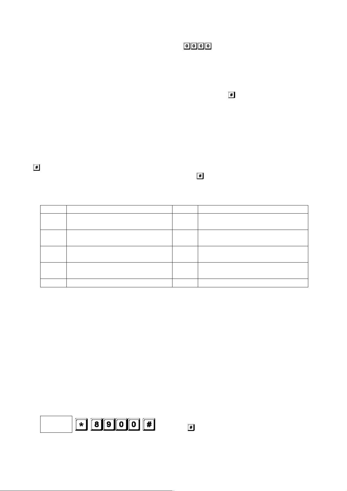
A) Programming procedures
a. Your HAA9523S is programmed from the eypad. All programmed information is stored in the non-volatile
memory.
b. Set the eypad into programming mode first with the master code and press to validate.
NOTE: Use the DAP jumper to set the eypad into programming mode in case you forgot the master code.
See “4. The DAP Jumper”.
c. Go to a location and program the options. See “6. Programming he Keypad – Summary Char ”.
d. Program the options until all options are programmed. Repeat the programming of an option in case of a
wrong entry.
LOCATION 1 OPTION
…
LOCATION n OPTION n
e. Exit the programming mode with . All input information has been saved.
B) Single user mode opera ion – Example
1. Requiremen s
a. Single user mode
b. Change the factory-set master code 0000 to a personal master code 3289
c. Set user code 1 to 8321
d. Set user code 2 to 6854
e. Set user code 3 to 9270
f. Set output 1 to momentary mode, 1 second
g. Set output 2 to start / stop mode
h. Set output 3 to start / stop mode
i. Set the eypad to loc itself during 15 minutes after 10 successive false codes
2. Programming – Se ing he above requiremen s in o he keypad
Program mode with factory-set master code

HAA9523S
v2 15/11/2013 VELLEMAN
10
Single user mode*
3289 stored as new personal master code and super user code
8321 stored as user code1 with duress code function for output 1
6854 stored as user code 2 for output 2
9270 stored as user code 3 for output 3
Output 1 set as momentary mode, 1 second
Output 2 set to start / stop mode
Output 3 set to start / stop mode
Keypad set to loc during 15 minutes after 10 successive false
codes
Exit programming mode. All above data stored and ready for use
NOTE: * Entering single user command code 8900 is not necessary if the eypad was already in single
user mode.
Cancel a wrong entry with or wait 10 seconds and retry.
3. Opera ing he keypad – Taking he da a programmed above and o her defaul fea ures as reference
a. To command an output, only enter the user code. Pressing is not required.
Output 1 activates for 1 second
Output 2 starts or stops
Output 3 starts or stops
b. The personal master code is a super user code to command the outputs. This feature allows you to use
only one code to operate several eypads with the same master code but different user codes. Enter
the personal master code and validate with and the corresponding output number.
Output 1 activates for 1 second
Output 2 starts or stops
Output 3 starts or stops
c. The duress code does not need to be programmed. The eypad automatically determines the duress
code by increasing the first digit of user code 1 with two units.
Example: If user code 1 is 1234, then the duress code will be 3234. If user code 1 is 8321, then the
duress code will be 0321.
To command the duress function, enter the duress code.
Duress
output
activat
es
(output switches to (
-
) ground) and
output 1 activates for 1 second
NOTE: The duress code has 2 functions: it activates the duress output and at the same time it activates
output 1 as user code 1. The duress code can always activate or deactivate (in start / stop mode)
output 1, but cannot deactivate (reset) the duress output.
HAA9523S
v2 15/11/2013 VELLEMAN
11
d. The accelerated code is the first two digits of the user code. If output 1 has been programmed in start /
stop mode with accelerated code at location 42, it will be possible to activate output 1 with only the first
two digits of the user code. Deactivation always requires the composition of the complete user code.
Example: Output 1 has been reprogrammed to start / stop mode with accelerated code (location 42).
Complete code: 8321, accelerated code: 83.
Output 1 starts
Output 2 stops
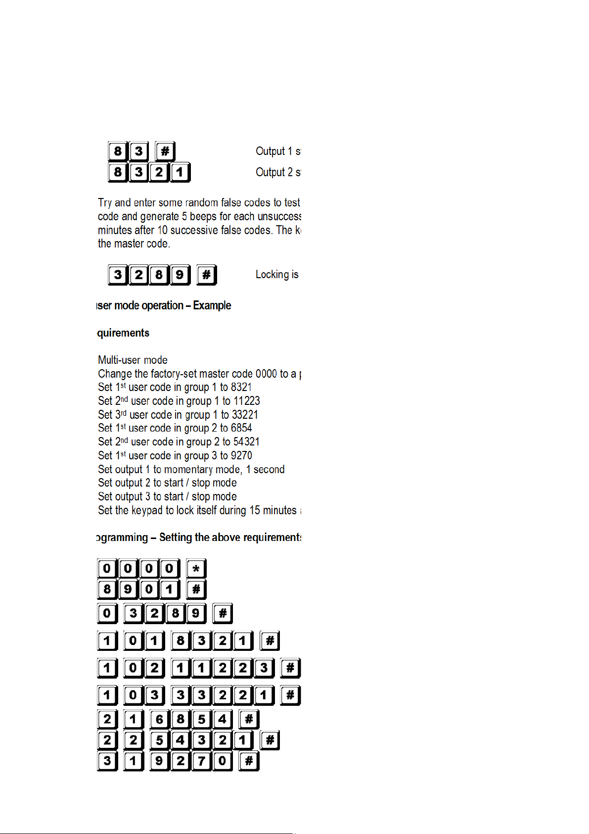
e. Try and enter some random false codes to test the safety. The HAA9523S will consider 4 digits as one
code and generate 5 beeps for each unsuccessful code entry. The eypad will loc itself during 15
minutes after 10 successive false codes. The eypad can be reset during the loc ing period by entering
the master code.
Loc ing is reset and eypad resumes normal operation
C) Mul i-user mode opera ion – Example
1. Requiremen s
a. Multi-user mode
b. Change the factory-set master code 0000 to a personal master code 3289
c. Set 1
st
user code in group 1 to 8321
d. Set 2
nd
user code in group 1 to 11223
e. Set 3
rd
user code in group 1 to 33221
f. Set 1
st
user code in group 2 to 6854
g. Set 2
nd
user code in group 2 to 54321
h. Set 1
st
user code in group 3 to 9270
i. Set output 1 to momentary mode, 1 second
j. Set output 2 to start / stop mode
. Set output 3 to start / stop mode
l. Set the eypad to loc itself during 15 minutes after 10 successive false codes
2. Programming – Se ing he above requiremen s in o he keypad
Program mode with factory-set master code
Multi-user mode*
3289 stored as new personal
master code and
super user code
8321 stored as 1
st
user code in group 1 with
duress code function
11223 stored as the 2
nd
user code in group 1 with
duress code function
33221 stored as the 3
rd
user code in group 1 with
duress code function
6854 stored as the 1
st
user code in group 2
54321 stored as the 2
nd
user code in group 2
9270 stored as the 1
st
user code in group 3
HAA9523S
v2 15/11/2013 VELLEMAN
12
Output 1 set to momentary mode, 1 second
Output 2 set to start / stop mode
Output 3 set to start / stop mode
Keypad set to loc during 15 minutes after 10
successive false codes
Exit programming mode. All above data stored and
ready for use
NOTE: * Entering single user command code 8901 is not necessary if the eypad was already in single
user mode.
Cancel a wrong entry with or wait 10 seconds and retry.
3. Opera ing he keypad – Taking he da a programmed above and o her defaul fea ures as reference
a. To command output 1, enter one of the user codes in group 1 and validate with .
Output 1 activates for 1 second
Output 1 activates for 1 second
Output 1 activates for 1 second
b. To command output 2, enter one of the user codes in group 2 and validate with .
Output 2 starts or stops
Output 2 starts or stops
c. To command output 3, enter one of the user codes in group 3 and validate with .
Output 3 starts or stops
d. The personal master code is a super user code to command the outputs. This feature allows you to use
only one code to operate several eypads with the same master code but different user codes. Enter
the personal master code and validate with and the corresponding output number.
Output 1 activates for 1 second
Output 2 starts or stops
Output 3 starts or stops
e. The duress code does not need to be programmed. The eypad automatically determines the duress
code by increasing the first digit of user codes in group 1 with two units. All user codes have duress
code function.
Example:
User codes in group 1
Corresponding duress codes
8321
0321
11223
31223
33221
53221

HAA9523S
v2 15/11/2013 VELLEMAN
13
To command the duress function, enter the duress code(s).
Duress
output
activates (output switches to ground) and output 1
activates for 1 second
Duress output activates (output switches to ground) and output 1
activates for 1 second
Duress output activates
(output switches to ground) and output 1
activates for 1 second
NOTE: The duress code has 2 functions: it activates the duress output and at the same time it activates
output 1 as user code in group 1. The duress code can always activate or deactivate (in start /
stop mode) output 1, but cannot deactivate (reset) the duress output. Only the user codes in
group 1 can deactivate (reset) the duress output.
f. The accelerated code is the first two digits of the user code(s). If the output has been programmed in
start / stop mode with accelerated code (programming option 42 for user codes in group 1 and
programming option 52 for user codes in group 2), it will be possible to activate the output with only the
first two digits of the user code(s). Deactivation always requires the composition of the complete user
code(s) in their code group.
Example: Output 1 has been reprogrammed to start / stop mode with accelerated code (location 42).
Complete code of the 1
st
user code in group 1: 8321, accelerated code: 83.
2
nd
user code in group 1: 11223, accelerated code: 11.
Output 1 starts
Output 1 stops
Output 1 starts
Output 1 stops
g. Try and enter some random false codes to test the safety. The HAA9523S generates 5 beeps for each
unsuccessful code entry. The eypad will loc itself during 15 minutes after 10 successive false codes.
The eypad can be reset during the loc ing period by entering the master code.
Loc ing is reset and eypad resumes normal operation
D) Dele ing a user in mul i-user mode
If you need to delete a user who no longer has authority to enter the protected area:
1. Set the system in programming mode with the personal master code and .
Keypad is in programming mode
2. Enter the user number (00~99 for output 1; 0~9 for output 2 and 3) and to delete a user code.
To delete user number 05 in group 1, press
To delete user number 3 in group 2, press
To delete user number 2 in group 3, press

HAA9523S
v2 15/11/2013 VELLEMAN
14
3. Continue deleting desired codes.
4. Exit the programming mode by pressing .
7. Technical Specifica ions
•Opera ion Vol age
12V-24V AC/DC, no jumper required for voltage selection
•Opera ion Modes
a) Single user mode, auto or manual code entry
b) Multi-user mode: 100 user codes for output 1 (user number 00-99), auto or manual code entry
10 user codes for output 2 (user number 0-9), auto or manual code entry
10 user codes for output 3 (user number 0-9), auto or manual code entry
•User Code Combina ions
a) Single user mode: 10 000
b) Multi-user mode: 111 110 000
•Inpu Sensing Terminals
a) Egress input: N.O. referring to (-) ground
b) Door position sensor input: N.C. referring to (-) ground
c) Relay 1 stop control: N.O. referring to (-) ground
•Relay Ou pu Con ac s
OUTPUT 1: N.C. and N.O. dry contacts, 5A / 30VDC max. rating
OUTPUT 2: N.C. and N.O. dry contacts, 1A / 30VDC max. rating
OUTPUT 3: NPN open collector, 100mA sin / 24VDC max.
•Tamper Swi ch Con ac
N.C. dry contact, 50mA max.
•Duress, In erlock and Key-Ac ive Ou pu Ra ing
NPN open collector switches to ground when active, 24DC / 100mA sin
•Au o Refreshing Time during Code En ry
a) Each digit max. entry time limit: 10 seconds
b) Each code max. entry time limit: 30 seconds
•Dimensions
117 x 74 x 48mm
•Weigh
180g
8. Applica ion Examples
1. Basic wirings of a s and-alone door
lock wi h inhibi au horiza ion code
and indica ion (fig. 2)
•Connect the 1N4004 as close as
possible to the loc in parallel with

HAA9523S
v2 15/11/2013 VELLEMAN
15
the loc power terminals in order to absorb the bac EMF and to prevent it from damaging the eypad. The
1N4004 is not required if the electric loc is AC-operated.
•To avoid electrostatic discharges, always ground the (-) terminal of the eypad to earth.
•The green LED lights while the eypad is stri ing the electric loc .
•The connection “output 3” to “output 1 disable” is optional. With this connection, output 3 will be used as an
authorization control. You may ey in user code 3 to stop the operation of the electric loc during daytime or
after office hours in order to prevent unauthorized access. Set output 3 in start / stop mode (programming
option 61) for on / off control. The red LED lights when the operation of the electric loc stops.
•Tape all unused wires to prevent short-circuit.
WARNING: For safety, ma e sure everybody has left the building before enabling the door loc inhibit
function. Only the owner should eep the inhibit authorization code.
2. Basic wirings for alarm arm-disarm and s and-alone door lock (fig. 3)
•This application is the same as
application 1 except for the
LED indications. The green and
red LEDs are used as alarm
status indications, such as exit,
armed, alarm memory, etc.
•Relay output 2 is used for the
alarm arm-disarm control.
Refer to the manual of your
alarm control panel.
•Connect the tamper switch to
the N.C. 24-hour zone and the
duress output to the N.O. 24-
hour zone for tamperproof and
emergency reporting.
•The connection “output 3” to
“output 1 disable” is optional.
With this connection, output 3
will be used as an authorization
control. You may ey in user
code 3 to stop the operation of
the electric loc at light or after
office hours in order to prevent
unauthorized access. Set output 3
in start / stop mode (programming
option 61) for on / off control. The
red LED lights when the operation
of the electric loc stops.
•The yellow green wire is the
common ground to lin up the
eypad and the alarm control
panel in order to achieve the
logical functions.
3. Basic wirings of an in erlock
sys em using 2 keypads (fig. 4)

HAA9523S
v2 15/11/2013 VELLEMAN
16
An interloc system needs 2 door controllers. This application uses 2 x HAA9523Ss with a simple crosswire
connection on “output 1 disable” and “interloc control output” terminals of both eypads. Lin up the (-) GND
terminals of both eypads as common ground in order to achieve the interloc functions. Connection of the
green LED is optional. It will light up when the loc is active when connected.
•Use the eypad to open the door from the outside.
•Press the egress button to open the door from the inside.
•Connect the magnetic sensors on door 1 and 2.
•During the time that door 1 is open, door 2 is forced to eep closed and vice versa.
•Use the N.O. relay output for fail-secure loc ing device and the N.C. output for fail-safe loc ing device.
•Relay output 2 is independent and has no concern with the interloc system. It may be used for other
applications.
4. Basic wirings of an in erlock sys em using 1 keypads and an in erlock con roller power supply (fig. 5)
This application uses one
HAA9523S and a power supply
with interloc controller. The
power supply provides power for
the whole system, including both
electric loc s and the eypad.
Ma e sure the total power
consumption of the system does
not exceed the maximum power
ratings of the power supply,
especially if fail-safe loc s are
used. The interloc function is
accomplished with a crosswire
connection of the “interloc
control output” and the “output 1
disable” terminals between the
eypad and the controller. Lin up
a common ground between the
eypad and the power supply to
set up a power path and to
achieve the interloc functions.
•Use the eypad to open door 1 from the outside.
•Open door 2 with egress button A from the outside while door 1 is closed.
•Open door 1 from the inside with the egress button and open door 2 with egress button 2.
•Connect the magnetic sensors on door 1 and 2.
•During the time that door 1 is open, door 2 is forced to eep closed and vice versa.
•Use the N.O. relay output for fail-secure loc ing device and the N.C. output for fail-safe loc ing device.
•Relay output 2 is independent and has no concern with the interloc system. It may be used for other
applications.
9. Applica ion Examples for he Auxiliary Facili ies
(A)Tamper N.C. (fig. 6)

HAA9523S
v2 15/11/2013 VELLEMAN
17
The tamper switch is N.C. while the eypad is secured on the gang box. To prevent sabotage, connect these
terminals in series with a N.C. 24-hour protection zone of an alarm if required.
(B)Door sens (fig. 7)
With the help of a N.C. door position sensor (usually a
magnetic door switch) on the door to set up the following
functions: door auto reloc , door forced-open alarm, door
propped-up alarm and interloc control (see “2.
Connec ions”)
(C)Key ac ive – Pink wire (fig. 8)
The ey-active output will switch to (-) ground for 10 seconds whenever a ey is pressed. Use it to turn on an
LED lamp and/or a small buzzer to notify a guard, to energize a relay to switch on lights or a CCTV camera…
•Ma e sure that the relay for switching on the lights has enough isolation between the high-voltage and low-
voltage to prevent damage to the eypad.
•Only one connection option is recommended. Ma e sure the sin current does not exceed the maximum
rating of 100mA.
•External power supply and isolation relay are necessary for driving high-power devices such as lights.
(D)Duress ou pu – Whi e/orange wire (fig. 9)
The duress output will switch to (-) ground when the duress code is entered. You may use it to turn on an LED
lamp and/or a small buzzer. Connect it to a N.C. 24-hour protection zone of an alarm system.
•Only one connection option is recommended. Ma e sure the sin current does not exceed the maximum
rating of 100mA.
(E)Ou pu 2
1. Shun ing an N.C. zone (white/brown and blue wires) (fig. 10)

HAA9523S
v2 15/11/2013 VELLEMAN
18
•Use the N.O. output contact to shunt a N.C. protection zone of an alarm system.
•Set the output contact to start / stop mode (programming option 51).
2. Alarm sys em arm-disarm con rol (white/brown and blue or purple wires) (fig. 11)
•Use the N.O. or the N.C. output contact to set the alarm system in arm-disarm mode.
•Refer to the manual of your alarm control panel for the appropriate output contact to be used in arm-
disarm control.
•Usually set output 2 to momentary mode (programming option 501) for multi-station systems and
start / stop mode (programming option 51) in single-station systems.
(F)Ou pu 3 (white/red wire) (fig. 12)
Output 3 is an open collector output prepared for auxiliary controls. It
may be used for arm-disarm of a security system, enabling and
disabling of a eypad or a protection zone, etc. It can also drive a relay
to give full function of N.C. and N.O. outputs.
For more info concerning his produc , please visi our websi e www.velleman.eu.
The informa ion in his manual is subjec o change wi hou prior no ice.

HAA9523S
v2 15/11/2013 VELLEMAN
19
GEBRUIKERSHANDLEIDING
1. Inleiding en kenmerken
Aan alle ingeze enen van de Europese Unie
Belangrijke milieu-informa ie be reffende di produc
Dit symbool op het toestel of de verpa ing geeft aan dat, als het na zijn levenscyclus wordt weggeworpen,
dit toestel schade an toebrengen aan het milieu.
Gooi dit toestel (en eventuele batterijen) niet bij het gewone huishoudelij e afval; het moet bij een
gespecialiseerd bedrijf terecht omen voor recyclage.
U moet dit toestel naar uw verdeler of naar een lo aal recyclagepunt brengen.
Respecteer de plaatselij e milieuwetgeving.
Heb u vragen, con ac eer dan de plaa selijke au ori ei en inzake verwijdering.
Dan u voor uw aan oop! Lees deze handleiding grondig voor u het toestel in gebrui neemt. Werd het toestel
beschadigd tijdens het transport, installeer het dan niet en raadpleeg uw dealer.
De HAA9523S is een onafhan elij en betrouwbaar beveiligingstoetsenbord aan een zacht prijsje en an gebrui t
worden in zowel woningen als bedrijven. Dit toetsenbord is compatibel met vrijwel el ele tronisch slot in
beveiligingssystemen, automatische scha elingen en machines. Er zijn meer dan 100 miljoen combinaties mogelij
voor de gebrui erscodes (multi-usercode). De gegevens worden in een niet-vluchtig geheugen bewaard. En el voor
gebrui binnenshuis.
2. Aanslui ingen (zie fig. 1)
DE LED-AANDUIDINGEN
•ROOD & GROEN
Verbind de rode en de groene leds naar goeddun en.
•AUX ROOD / GROEN
De groene led is een statusaanduiding tijdens de normale wer ing. De led verandert naar vast rood terwijl de
AUX rode led wordt geactiveerd.
HET AANSLUITBLOK
•OUTPUT 1
5A droog relaiscontact voor een deurscha elaar. Normaal open (N.O.) en normaal gesloten (N.C.) uitgangen zijn
ver rijgbaar. Gebrui de N.O.-uitgang voor een slot in arbeidsstroom (fail-secure) en een N.C.-uitgang voor een
slot in ruststroom (fail-safe). Het relais an worden geprogrammeerd in start-stopmodus (scha eling) of
timermodus van 1 tot 999 seconden.
•EG IN (EGRESS-ingang)
Een N.O.-ingangsterminal wordt aangesloten op de (-) aarding door middel van een N.O.-toets om relaisuitgang 1
te deactiveren. De egress-toets wordt doorgaans binnenshuis naast de deur geplaatst. U unt meer dan één
egress-toets parallel aan de terminal aansluiten. Laat de aansluiting open wanneer u deze niet gebrui t.
•12V-24V AC/DC (VOEDINGSINGANG)
Sluit een 12V-24V AC/DC voeding aan. De (-) lem en de GND (aarding, abel 15) zijn gemeenschappelij e
aardingspunten. Er is geen brug nodig voor het gehele berei van de ingangsspanning. Verbind de gelij spanning
met de (+) en de (-); er is geen onderscheid voor de wisselspanning.

HAA9523S
v2 15/11/2013 VELLEMAN
20
•DOOR SENS (INGANG VAN DE DEURSENSOR)
Een N.C.-ingangsterminal aangesloten op de (-) aarding. Samen met een N.C. magnetische deurscha elaar zal
het systeem de stand van de deur bepalen en volgende functies geven:
1. Au oma ische deurvergrendeling
Het systeem vergrendelt automatisch de deur na het ingeven van een geldige code vóór het einde van de
programmeertijd voor uitgang 1.
2. Alarm bij geforceerde deur
Het systeem genereert onmiddellij een alarmsignaal wanneer de deur wordt geforceerd zonder een geldige
gebrui erscode of egress-ingang. Het alarmsignaal duurt 60 seconden en an worden onderbro en met
gebrui erscode 1 of één van de gebrui erscodes in groep 1. Deze functie is selecteerbaar via de
programmeeropties op locatie 801.
3. Alarm bij open deur
Alarm wanneer de deur langer dan de toegestane tijd open blijft staan, m.a.w. het alarm gaat af na het
verlopen van de ingestelde tijd tot de deur opnieuw wordt gesloten. De tijd is instelbaar van 1 tot 999
seconden op locatie 9.
4. Sassys eem
Aansluiting op (-) terwijl de deur open is zodat het signaal wordt gegeven om de andere deur van het
sassysteem te openen.
DE KABELBOOM
OPMERKING: Houd de printplaat stevig vast en tre voorzichtig aan de plug zodat u de ele tronica niet beschadigd.
•N.C. TAMPER (1-2)
N.C.-contact wanneer het toetsenbord aan de doos bevestigd is. Het wordt geopend wanneer het frontpaneel van
de doos verwijderd wordt. Sluit deze uitgang in serie aan de 24-uur noodscha eling op uw alarmsysteem indien
gewenst.
•GROENE, RODE & AUX RODE LEDS (3-4), (5-6) & (7)
Er zijn 3 leds op het paneel voorhanden. Ze werden voorbereid om er om het even wel e functie op aan te sluiten.
Wij stellen voor om deze leds aan de indicatieaansluitingen van uw alarmcontrole paneel aan te sluiten. Houd de
juiste polariteit in het oog.
De groene en de rode onafhan elij e leds zijn voorzien van een 1.5 Ω stroombeper ende weerstand.
De anode van de AUX rode led wordt intern aangesloten op de +5V en wordt ingescha eld met de athode ( abel
7) aangesloten op de (-) aarding.
•ACTIEVE UITGANG OF ALARMUITGANG (8)
Opencollectoruitgang van een NPN transistor van max. 100mA sin en 24VDC. Selecteerbaar via de K- of A-
jumper voor de actieve uitgang of alarmuitgang.
1. Ac ieve ui gang (KEY)
Scha elt gedurende 10 seconden naar de (-) aarding bij el e dru op de toets. Wordt gebrui t voor het
inscha elen van verlichting, CCTV-camera’s of zoemers.
2. Alarmui gang (AL)
Scha elt naar de (-) aarding wanneer het alarm bij geforceerde of open deur afgaat. Zo wordt een extern
alarm ingescha eld.
•UITGANG 2 (9-10-11)
Table of contents
Languages:
Popular Gateway manuals by other brands


MC Technologies
MC Technologies MC100 Terminal user manual

Multitek
Multitek MULTIcell FCT user manual

LevelOne
LevelOne VOI-8002 Integration manual

Clear Systems
Clear Systems Andino instruction manual

Alcatel-Lucent
Alcatel-Lucent CellPipe 7130 user manual

SHYAM Networks
SHYAM Networks HG400 quick start guide


