manuals.online logo
Brands
  1. Home
  2. •
  3. Brands
  4. •
  5. GE
  6. •
  7. Gateway
  8. •
  9. GE MDS WiYZ User manual

GE MDS WiYZ User manual

05-4888A01, Rev. B MDS WiYZ Gateway Setup Guide 1
MDS WiYZ Gateway
Publication No. 05-4888A01, ev. B
The MDS WiYZ p atform a ows the connection of process sensors
to a wire ess network. Wire ess y networked sensors a ow moni-
toring and contro of equipment and processes without the infra-
structure requirements of a hard-wired system. The WiYZ
p atform’s IP65 Outdoor Rating a ows insta ation of the gateway
and remotes outdoors, if required.
The WiYZ system consists of a gateway and up to 50 remote units.
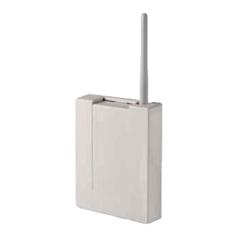
This startup guide discusses primari y the WiYZ Gateway shown in
Figure 1.
In addition to these instructions, the MDS WiYZ Technical Manual
(05-4954A01) provides he pfu guidance on WiYZ systems and
menus. A so refer to the MDS WiYZ Remote Setup Guide
(05-4953A01). E ectronic copies of a user documents and data
sheets are avai ab e free of charge at www.gemds.com.
1.1 WiYZ Gateway
The WiYZ Gateway is a wire ess mu tifunction network product that
provides connectivity between oca Ethernet networks, seria
devices or wire ess data co ection nodes, and a remote data
center or host system. It is idea y suited for demanding app ica-
tions where range and re iabi ity are important. The Gateway can
be optiona y equipped with an integra ce u ar modem for connec-
tivity to the pub ic ce u ar infrastructure.
This unique mix of wire ess techno ogy and data connectivity types
offers new so utions for users requiring re iab e communication
with remote networks and monitoring devices where communica-
tion or operating power is imited. The fo owing tab e ists the radio
interfaces the Gateway is capab e of operating with.
Figure 1. WiYZ Gateway
1.2 Accessories
GE MDS offers an Accessories Selection Guide isting additiona
items that may be used with our products. Contact your factory rep-
resentative or visit www.gemds.com for the atest copy.
2.1 WiYZ Gateway Installation
Refer to Figure 2 during these steps, as required:
1. Mount the WiYZ Gateway. Can be mounted using a wa
mount p ate, a po e mount, or strapped to a mast.
2. Connect an Ethernet Cable (regular or crosso er) to the
WiYZ Gateway’s LAN port.
3. Connect power to the WiYZ Gateway. The WiYZ Gateway
requires 10 to 30 Vdc. Use supp ied power cab e.
2.2 COM1 RS-232 DCE Diagnostic Pinouts
(DB9 Connector)
2.3 COM2 RS-232 DCE Payload Pinouts
(DB9 Connector)
1.0 INTRODUCTION
Radio Interface/
Typical Range Purpose
Frequency
(MHz)
Mesh
<1500 feet (457m)
Connect to WiYZ Remotes for
sensor/instrument data gathering.
2400
Wi-Fi
<300 feet (91m)
Wi-Fi c ient or Wi-Fi AP for
backhau or wire ess LAN.
2400
Ce u ar
<2500 feet (762m)
Ce u ar modem for backhau
(requires data service p an).
NOTE: DOES NOT SU ORT
VOICE COMMUNICATIONS
800-900
and
1700-1900
MDS Radio
<15 Mi es (24km)
MDS entraNET (proprietary) radio
for backhau or ong range
wire ess LAN.
900
2.0 HARDWARE INSTALLATION
Pin
Number
Input/
Output Pin Description
1 OUT DCD (Data Carrier Detect/Link)
2 OUT RXD (Recei ed Data)—Supp ies
received data to the connected device.
3 IN TXD (Transmitted Data)—Accepts TX
data from the connected device.
4 IN DTR
5 -- Ground—Connects to ground (negative
supp y potentia ) on chassis.
6 OUT DSR
7 IN RTS (Request to Send)
8 OUT CTS (Clear to Send)
9 -- No function in most app ications—User
I/O for specia app ications
Pin
Number
Input/
Output Pin Description
1 -- --
2 OUT RXD (Recei ed Data)—Supp ies
received data to the connected device.
3 IN TXD (Transmitted Data)—Accepts TX
data from the connected device.
4 -- --
5 -- Signal Ground—Connects to ground
(negative supp y potentia ) on chassis.
2 MDS WiYZ Gateway Setup Guide 05-4888A01, Rev. B
Figure 2. WiYZ Gateway External Connectors
This section describes web-based configuration. If you wish to use
seria contro via COM1, proceed to Section 4.0 instead.
In the steps that fo ow, you wi og into the WiYZ Gateway’s Web
interface and begin to set the basic operating parameters.
NOTE: Consu t your System Administrator if you are unsure of
the proper configuration settings for your network.
1. Connect computer’s Ethernet cab e to the Gateway’s LAN
connector. Open a web browser and navigate to
https://192.168.1.1. (You might need to change the PC’s IP
address to 192.168.1.x).
Defau t username: admin
Defau t password: admin
2. Using the Configuration>>Time & Identity screen, update
the Gateway’s device information and date/time settings.
3. Configuration of the Gateway wi be unique for every insta a-
tion. Using the bui t-in menu system, set up and configure the
Gateway and Remote units per system requirements. Setup
Wizards are provided to simp ify configuration for common
arrangements.
Refer to the MDS WiYZ Technical Manual (05-4954A01) for
additiona detai s on menu settings. Key areas for consider-
ation inc ude the fo owing items:
• Radio Interfaces
• IP & Networking
• Services
• Security
• Mesh Network
Seria -based configuration of the WiYZ Gateway is primari y imited
to basic configuration settings. For genera setup and configuration
use web-based configuration as described in Section 3.0.
In the steps be ow, you wi og into the Gateway’s conso e menu
system and begin to set the basic operating parameters.
NOTE: Consu t your System Administrator if you are unsure of
the proper configuration settings for your network.
1. Attach computer’s seria cab e to COM1 (115200 bps, 8N1).
2. Start a termina program such as HyperTermina .
3. Press the Enter key to obtain the ogin prompt.
Defau t username: admin
Defau t password: admin
4. Enter the ipconfig command to view current networking
setup.
5. Configuration of the network interfaces uses the ipconfig
command—enter ipconfig help to view syntax and options.
6. Type help to see other avai ab e commands and
< alid command> help for syntax and options on a particu ar
command.
In-service operation of the WiYZ Gateway is comp ete y automatic.
The on y operator actions required are to app y power and check
the front pane LEDs for proper indications as described be ow.
Figure 3. LED Status Indicators
6 -- --
7 IN RTS (Request-to-Send)—Keys the
transmitter.
8 OUT CTS (Clear-to-Send)—Goes “high” after
the programmed CTS de ay time has
e apsed (DCE), or keys another
connected radio when RF data arrives
(CTS KEY).
9 -- Reserved—User I/O for specia
app ications
3.0 SOFTWARE CONFIGURATION
(WEB-BASED)
Pin
Number
Input/
Output Pin Description
4.0 SOFTWARE CONFIGURATION
(SERIAL-BASED)
5.0 IN-SERVICE OPERATION
LED Name Function
Power Off—Power not app ied.
On—Power app ied.
Blinking—A arms present.
Mesh Off—Mesh disab ed.
Red—Mesh enab ed, no connected Remotes.
Green—Mesh enab ed, at east one connected
Remote.
Continued on next page...
05-4888A01, Rev. B MDS WiYZ Gateway Setup Guide 3
If troub e occurs, verify that the unit meets the fo owing basic oper-
ating requirements: 1) Adequate and stable primary power, 2)
Secure cable connections, and 3) Proper interface configura-
tions. These items shou d be checked prior to starting any detai ed
troub eshooting or ca ing for factory assistance.
6.1 LEDs
The gateway’s LED indicator pane provides usefu information
when troub eshooting SDA prob ems. Refer to Figure 3 and its
accompanying tab e for LED data.
6.2 Antenna Checks
Over-the-air communication/range troub es can often be traced to
improper antenna insta ation or unit p acement. The fo owing
checks shou d be made if there is a signa strength prob em in the
network:
• Make sure that the correct antenna is insta ed on each port
(see Figure 1) and that each antenna is tight y secured.
• Insta the WiYZ Gateway so that the antennas are vertica .
• Insta the unit as high as possib e to maximize signa
strength.
• Insta the unit in a ocation that is ine-of-sight to the associ-
ated remote units.
• Avoid p acing the unit near other antennas or wire ess equip-
ment.
• Avoid p acing the unit near arge meta objects.
6.3 Technical Assistance
Factory technica assistance is avai ab e by contacting GE MDS
during business hours (8:30 AM to 6:00 PM Eastern Time). Use
one of the fo owing means to contact the factory:
Te ephone: (585) 241-5510
E-mai : [email protected]
Web: www.gemds.com
FAX: (585) 242-8369
FCC Part 15 Notice
This Equipment has been tested and found to comp y with the imits for a C ass
A digita device, pursuant to Part 15 of the FCC Ru es. These imits are designed
to provide reasonab e protection against harmfu interference when the equip-
ment is operated in a commercia environment. This equipment generates,
uses, and can radiate radio frequency energy and, if not insta ed and used in
accordance with the instruction manua , may cause harmfu interference to radio
communications. Operation of this equipment in a residentia area is ike y to
cause harmfu interference in which case users wi be required to correct the
interference at their own expense.
This device comp ies with Part 15 of the FCC Ru es. Operation is subject to the
fo owing two conditions: (1) this device may not cause harmfu interference, and
(2) this device must accept any interference received; inc uding interference that
may cause undesired operation.
FCC Notice for CDMA Module
This PCII adds AMPS operation to previous fi ing. Modu e Approva . Power
Output isted is conducted. The antenna gain, inc uding cab e oss, must not
exceed 9.5 dBi at 1900 MHz/2.26 dB at 850 MHz for mobi e operating configu-
rations and 13.5 dBi at 1900 MHz/2.93 dB at 850 MHz for fixed-mount opera-
tions, as defined in 2.1091 and 1.1307 of the ru es for satisfying RF exposure
comp iance. Separate approva is required for portab e operating configurations,
as defined in 2.1093 of the ru es. The fina product operating with this transmitter
must inc ude operating instructions and app icab e warnings, as described in this
fi ing, for end-users and insta ers to satisfy RF exposure comp iance require-
ments. OEM integrators must be informed of the specific requirements.
RF Exposure Notice
To comp y with RF exposure requirements, the antenna sha be insta ed to
ensure a minimum separation distance of 20 cm from persons. The antenna
may not be co ocated or operated in conjunction with other transmitting devices.
To reduce potentia radio interference to other users, the antenna type and its
gain shou d be so chosen that the Equiva ent Isotropica y Radiated Power
(EIRP) is not more than that permitted for successfu communication.
Only appro ed antennas may be used on the unit's RF output connectors,
as listed below. The use of non-appro ed antennas may result in a iola-
tion of FCC rules, and subject the user to FCC enforcement action.
Warning: Changes or modifications not expressly approved by the manufacturer
could void the user’s authority to operate the equipment.
Wi-Fi Station Operation or Ad-Hoc Operation:
•Off—No connection.
•Solid green—Connected with “good” signa
(RSSI stronger than -48 dBm).
•Solid amber—Connected with “medium” signa
(RSSI between -49 dBm and -69 dBm).
•Solid red—Connected with “weak” signa (RSSI
ess than -70 dBm).
AP Mode:
•Off—Wi-Fi disab ed.
•Solid green—One or more connected c ients.
•Solid red—No connected c ients.
Ce Off—No ce u ar connection.
Solid green—Ce u ar connection with a good signa
(RSSI stronger than -80 dBm).
Solid amber—Ce u ar connection with a medium
signa (RSSI between -90 dBm and -80 dBm).
Solid red—Ce u ar connection with a weak signa
(RSSI ess than -90 dBm).
eNET entraNET Remote Operation:
•Off—No connection.
•Solid green—Connected with “good” signa
(RSSI stronger than -75 dBm).
•Solid amber—Connected with “medium” signa
(RSSI between -76 dBm and -95 dBm).
•Solid red—Connected with “weak” signa (RSSI
ess than -96 dBm).
entraNET Direct-Mode Node Operation:
•Off—Disab ed.
•Solid green—One or more Remotes connected
to a direct mode Root.
•Solid red—No Remotes connected to a direct
mode Root.
entraNET Direct-Mode Root Operation:
•Off—Disab ed.
•Solid green—Avai ab e for connected Remotes.
LAN Off—No Ethernet ink.
On—Ethernet ink estab ished.
Flash—Ethernet data on interface.
COM1 B inks if TX or RX data is present on COM1 interface.
COM2 B inks if TX or RX data is present on COM2 interface.
6.0 TROUBLESHOOTING
LED Name Function
Connector Allowed Antennas
(GE MDS Part Number)
N-Connector Mesh Omni (2.4 GHz):
97-4278A48
Wi-Fi Omni (2.4 GHz):
97-4278A48
Ce u ar Omni (800/1900 MHz):
97-4278A47
entraNET Omni: 97-4278A49
entraNET Yagi: 97-3194A14

GE MDS, LLC
175 Science Parkway
Rochester, NY 14620
MDS WiYZ Gateway Setup Guide Genera Business: +1 585 242-9600
05-4888A01, Rev. B FAX: +1 585 242-9620
August 2011 Web: www.gemds.com
The tab e be ow shows the hierarchy and avai ab e se ections of
the WiYZ Gateway’s menu system. The system a ows comp ete
configuration, maintenance, and system monitoring using the Web
interface. For detai ed information on menu se ections not
described here, refer to the WiYZ Technical Manual (05-4954A01).
To protect against unauthorized use, a unique password shou d be
set for the menu system as soon as possib e after the equipment
is received. The factory defau t password (
admin
) is intended on y
for initia ogin by a new user, and shou d be changed using the
Security Configuration Menu.
7.0 USER MENU OVERVIEW
Top Le el
Menu Sub-Path Title Menu Title
Overview Summary WiYZ Summary
-- -- Hea th & Maintenance Summary
-- -- IP Address Summary
-- -- Configuration Summary
Setup
Wizards Basic Wizards Seria Configuration
-- -- Setup Wizards
Configura-
tion Identity & Time Device Information
-- -- Date and Time Configuration
-- Radio Interfaces Wi-Fi Status
-- -- Wi-Fi Configuration
-- -- MDS Radio Configuration
-- -- Ce u ar Status
-- IP & Networking Bridge
-- -- LAN Port
-- -- MDS Radio
-- -- Wi-Fi
-- -- Ce u ar
-- -- VPN
-- -- Routing and Firewa Config.
-- -- Firewa Ru e Tab e
-- Services TFTP Configuration
-- -- SNMP Configuration
-- -- Data Reporting Service
-- -- VPN Configuration
-- -- Modbus TCP Configuration
-- -- Modbus TCP IO Registers Map
-- -- Export Modbus TCP IO Registers
Map
-- Security Management Configuration
-- -- Authentication
-- -- RADIUS Configuration
-- -- Certificate Import
-- -- Authorization
Maintenance
& Status Events & A arms Active A arms
-- -- A erts Log
-- -- Export A erts Log
-- -- System Log
-- Performance Network Statistics
-- -- Wi-Fi Status
-- -- Seria Statistics
-- -- MDS Radio Statistics
-- -- Bridge Status
-- Diagnostics Ping Test
-- -- Generate Support Package
-- Configuration
Fi es Export Database Configuration
-- -- Import Database Configuration
-- -- Reset Database Configuration
-- Firmware Uti ities Version Information
-- -- Firmware Reprogramming
-- -- Copy Image
-- -- Verify Image
-- -- Device Reboot
Mesh
Network Provisioning Mesh Networking
-- -- Device Access Contro List
-- Status Devices
-- Manage Fie d
Devices Device Information Summary
-- -- Profi e Configuration
-- -- Modbus Register Map
-- -- Loca -Loop Connections
-- Device Profi es Manage Profi es
-- -- Import/Export Profi es
-- I/O Database I/O Database Graphing
-- -- I/O Database Information
-- -- Export I/O Database Information
-- Diagnostics Wire ess Device Summary
-- -- Channe Status
-- -- Neighbor Hea th List
-- -- Neighbor Graph List
-- -- Superframe List
-- -- Superframe Links List
-- Termina Servers Device Termina Server
-- Device Firmware Device Firmware Upgrade
-- Network Map Mesh Network Map
End of Menu Overview
Top Le el
Menu Sub-Path Title Menu Title

Other GE Gateway manuals

GE PACSystems RX3i Genius User manual

GE

GE PACSystems RX3i Genius User manual

GE Interlogix 0150-0265A User manual

GE

GE Interlogix 0150-0265A User manual

GE GCG001 User manual

GE

GE GCG001 User manual

GE NX-592E-GSM User manual

GE

GE NX-592E-GSM User manual

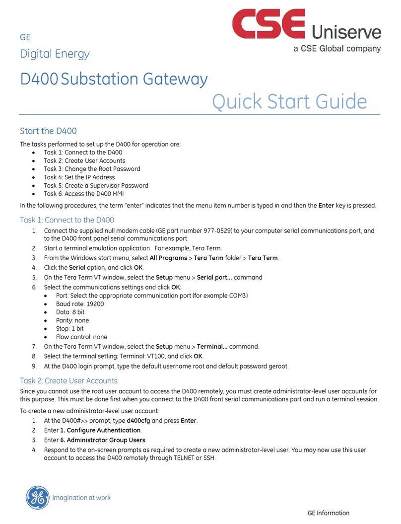
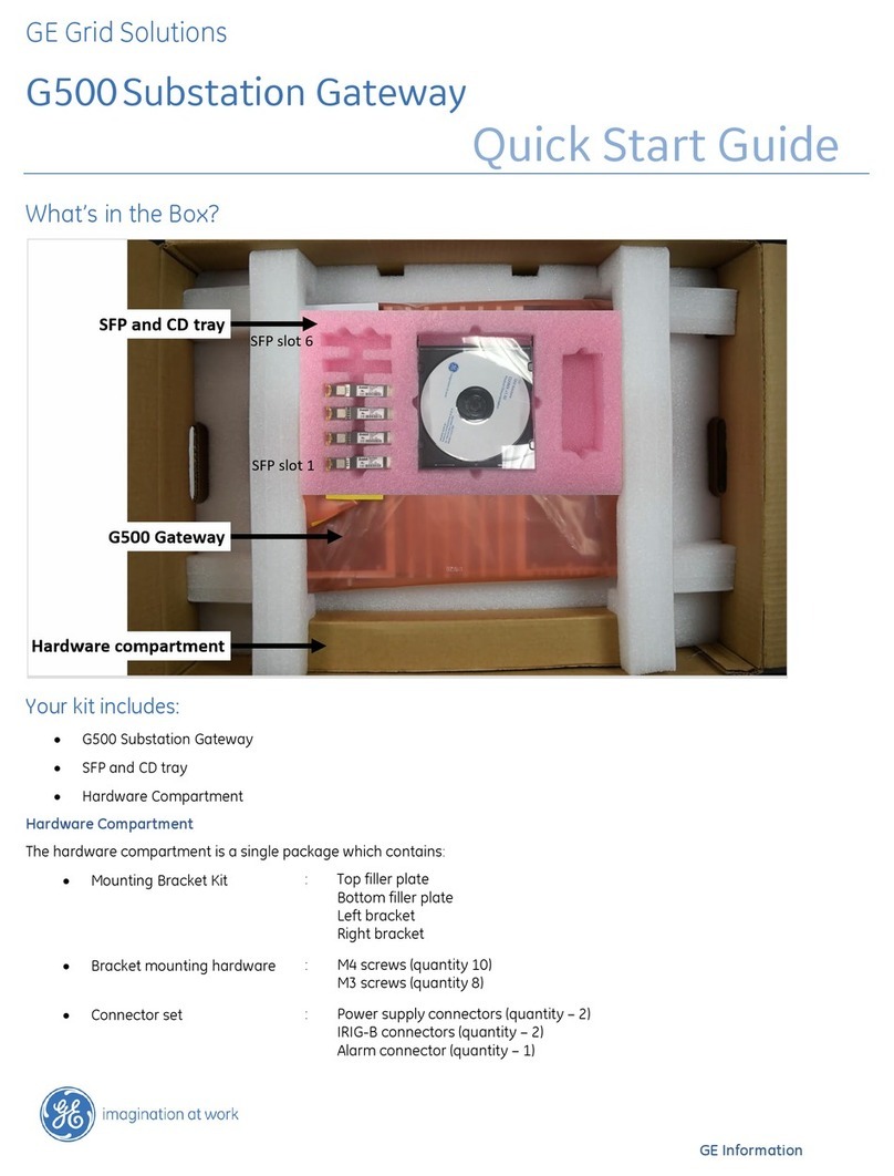
GE G500 User manual

GE

GE G500 User manual

GE 3500/91 EGD User manual

GE

GE 3500/91 EGD User manual

GE GFK-2892F User manual

GE

GE GFK-2892F User manual

GE ProBridge User manual

GE

GE ProBridge User manual

GE G500 User manual

GE

GE G500 User manual

GE Multilin D400 User manual

GE

GE Multilin D400 User manual

GE Multilin D400 User manual

GE

GE Multilin D400 User manual

GE POWER LEADER GEH-6505A User manual

GE

GE POWER LEADER GEH-6505A User manual

GE Multilin D400 Instructions for use

GE

GE Multilin D400 Instructions for use

Popular Gateway manuals by other brands

Dialogic IMG 1010 quick start guide

Dialogic

Dialogic IMG 1010 quick start guide

ViewSonic Wireless Media Gateway WMG80 user guide

ViewSonic

ViewSonic Wireless Media Gateway WMG80 user guide

Mediatrix 3000 Series Specifications

Mediatrix

Mediatrix 3000 Series Specifications

AddPac VoiceFinder AP-MG3000N installation guide

AddPac

AddPac VoiceFinder AP-MG3000N installation guide

ipDatatel Gateway 3.0 installation manual

ipDatatel

ipDatatel Gateway 3.0 installation manual

OpenVox SWG20 4S Series user manual

OpenVox

OpenVox SWG20 4S Series user manual

Chipkin CAS-2700-24 user manual

Chipkin

Chipkin CAS-2700-24 user manual

ViewSonic WPG-150 - Wireless Video Extender user guide

ViewSonic

ViewSonic WPG-150 - Wireless Video Extender user guide

AudioCodes MediaPack MP-263 quick guide

AudioCodes

AudioCodes MediaPack MP-263 quick guide

Icom VE-PG4 installation guide

Icom

Icom VE-PG4 installation guide

Grandstream Networks GXW-410xv user manual

Grandstream Networks

Grandstream Networks GXW-410xv user manual

SMSEagle NXS-9750-3G user manual

SMSEagle

SMSEagle NXS-9750-3G user manual

B+B SmartWorx SmartSwarm 342 Quick start guides

B+B SmartWorx

B+B SmartWorx SmartSwarm 342 Quick start guides

Wiznet WIZ100SR user manual

Wiznet

Wiznet WIZ100SR user manual

AAMP of America iSimple owner's manual

AAMP of America

AAMP of America iSimple owner's manual

MSA QuickServer FS-QS-2XX0 operating manual

MSA

MSA QuickServer FS-QS-2XX0 operating manual

RAK RAK7244 quick start guide

RAK

RAK RAK7244 quick start guide

Pepperl+Fuchs VBG-PB-K25 manual

Pepperl+Fuchs

Pepperl+Fuchs VBG-PB-K25 manual

manuals.online logo
manuals.online logoBrands
  • About & Mission
  • Contact us
  • Privacy Policy
  • Terms and Conditions

Copyright 2025 Manuals.Online. All Rights Reserved.