Velocitek SC-1 User manual

SC-1 Reference Manual
Firmware Version 2.4F (Full Functionality)

Contents
INTRODUCTION 1
SC-1 FEATURES 1
MANUAL ORGANIZATION 1
ON THE WATER 2
DEVICE OVERVIEW 2
DISPLAYS 2
BUTTONS 3
BATTERY LIFE INDICATOR 4
GETTING STARTED 5
INSERTING BATTERIES 5
LOCK FEATURE 6
UNLOCKING PROCEDURE 7
TURNING POWER ON8
TURNING POWER OFF 9
SIGNAL ACQUISITION 10
OPERATING MODES 11
LOWER DISPLAY MODE SELECTION 12
UPPER DISPLAY MODE SELECTION 13
SPEEDOMETER MODE 14
COMPASS MODE 16
TACTICAL COMPASS MODE 19
VMG MODE 23
TIMER MODE 26
START LINE PROXIMITY MODE 31
DATA LOGGER MODE 35
WHEN YOU GET HOME 36
SOFTWARE INSTALLATION REQUIRED TO DOWNLOAD GPS DATA FROM YOUR DEVICE 36
INSTALLING CONTROL CENTER 36
INSTALLING DRIVERS FOR YOUR VELOCITEK DEVICE 50
USING CONTROL CENTER 54
SC-1 GPS DATA STORAGE 54
DOWNLOADING GPS DATA 55

SAVING GPS DATA 59
CLEARING GPS DATA 67
UPDATING USER INFORMATION 68
UPDATING DEVICE SETTINGS 69
UPDATING FIRMWARE 72
LAUNCHING GPS ACTION REPLAY FROM CONTROL CENTER 74
MAINTENANCE 75
CONTACT 76
INDEX 77

SC-1 Features 1
Introduction
SC-1 Features
The SC-1 is a powerful sail training tool designed to provide you with the feedback you need to sail
faster. The SC-1 has the following features:
Speed, compass, tactical compass, VMG and start line proximity updated at 2 times a second
Start timer with user configurable timer rollover and start sequence
Ability to display any two measurements simultaneously
Maximum and best 10 second average speed recall
Adjustable damping
Up to 20 hours of battery life
User configurable device settings allow customization of select SC1 functionalities
Over 20 hours of GPS data storage at record rate of every 2 seconds
Data downloading through a USB link
Downloaded data is easily formatted for use with Kattack, Google Earth and GPS Action Replay
Internet updatable firmware allows you to benefit from ongoing product improvements and
feature additions
Manual Organization
This manual is divided into 2 main sections. The first section, On The Water describes how to use the
SC-1 to obtain real-time feedback while you are sailing. The second section, When You Get Home
describes how to download and view GPS data from your SC-1 using a PC.

Device Overview 2
On the Water
Device Overview
Displays
The following diagram shows the SC-1's two main display areas:
The upper and lower displays can both be used to display speed, heading, tactical heading, VMG, start
line proximity or timer information. The information shown on each display is made clear by a mode
indicator immediately to the left of the numerical display area. There is no “TIMER” indicator on the
upper display. Timer mode on the upper display is indicated simply by the presence of a colon between
the minutes and seconds. Additionally there is no start line proximity mode indicator in both upper and
lower display. No mode indicators will be displayed in either screen when the device is in start line
mode. Tactical compass mode is indicated by presence of both "COMPASS" and "VMG" indicators.
The first decimal point on the upper display is used as an unlock indicator if any of the lock features are
enabled. The indicator is not displayed if all lock features are disabled.

Device Overview 3
Buttons
The SC-1 is controlled by four different capacitive touch sensors. These touch sensors detect the
presence of your thumbs when they are placed on top of the regions shown in the following diagram:
The captions on the above diagram indicate how the different touch sensors will be referred to in the
rest of this manual.

Device Overview 4
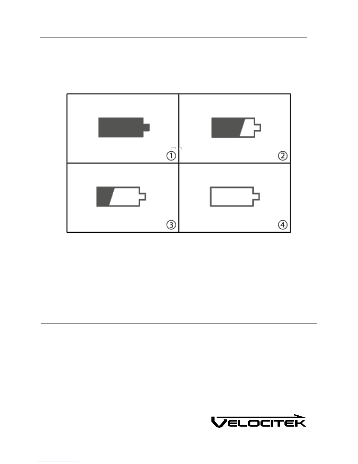
Battery Life Indicator
The battery life indicator is located in the top left corner of the SC-1. As the energy in the device's
batteries is consumed, the battery life indicator will undergo the following progression to show you how
much run time you have left:
1 When the indicator is fully illuminated you have approximately 20 hours of battery life remaining.
2 When the indicator is two thirds illuminated you have less than 15 hours of battery life remaining.
3 When the indicator is one third illuminated you have less than 10 hours of battery life remaining.
4 When the indicator is not illuminated you have less than 5 hours of battery life remaining.
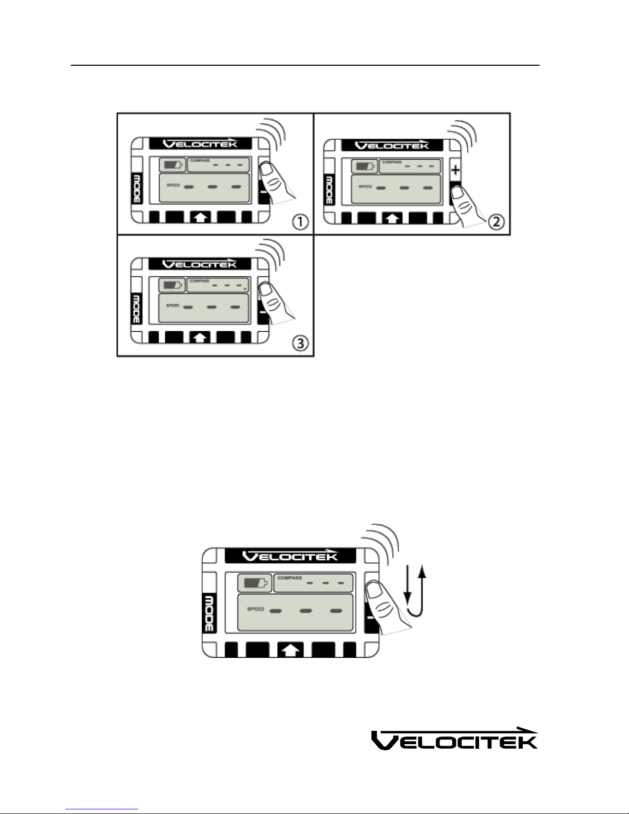
When the batteries are too low to properly power the GPS chipset the whole display will go blank and
flash "LO" in the lower display.
Note: The above applies for rechargeable nickel metal hydride (NiMH) batteries. Disposable alkaline
batteries will provide approximately half the life of NiMH batteries. Also with disposable batteries,
there will be a tendency for the life indicator to remain fully illuminated for most of the battery life and
only drop down to the lower levels when the batteries are nearly exhausted.
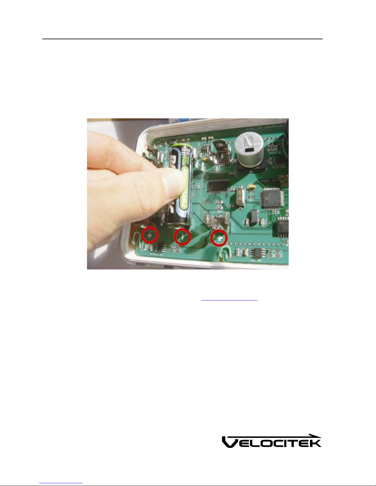
The SC-1 will slowly deplete batteries even when it is turned off. Fully charged batteries will be
exhausted in about 100 days when the device is left turned off. For long term storage, remove any one
of the three batteries from the device to prevent this slow drain.

Getting Started 5
Getting Started
Inserting Batteries
Open the waterproof case and insert three AA batteries into the metal clips on the circuit board. Be
careful to orient the batteries according to the polarity markings on the circuit board. These markings are
circled in red on the following photograph:
The SC-1 will work with rechargeable nickel metal hydride (NiMH) batteries or standard disposable AA
batteries. Disposable batteries will provide approximately 10 hours of life while rechargeable NiMH
batteries will last for 20 hours or longer. The remaining battery life indicator on the SC-1 is calibrated
to work with rechargeable NiMH batteries.

Getting Started 6
Lock Feature
The Velocitek SC-1 uses touch sensors to accept user input. Splashing water can trigger the touch
sensors. To prevent the device from being inadvertently controlled by splashing water the user can
enable lock features. When the device is locked, buttons are non-functional. There are two lock
features:
Speed Lock: The unit locks when the device speed exceeds the speed lock value (knots).
During speed lock, the unit will not allow the user to unlock the buttons.
Timeout Lock: The unit locks when the buttons have been inactive for a time period over the
timeout lock value (seconds). During a timeout lock, the unit allows the user to unlock the
buttons.
Speed lock enable, speed lock value, timeout lock enable and timeout lock value are all configurable in
device settings. The speed lock and timeout lock can be enabled independently.
The device will lock in response to the following events if timeout lock is enabled:
The timer is started
The timer is synchronized
When both lock features are disabled, the unlock indicator is never shown.

Getting Started 7
Unlocking Procedure
1 Cover the plus button with your thumb.
2 When you hear a beep, move your thumb to the minus button.
3 When you hear another beep, move your thumb back to the plus button. A long beep indicates
that you have successfully unlocked the device. The unlock indicator will be displayed if the lock
feature is enabled. All buttons will now respond to your input.
The unlocking procedure can be executed very quickly by sliding your thumb back and forth over the plus
and minus buttons as shown below:

Getting Started 8
Turning Power On
Use the following procedure to turn on the SC-1:
1 Use your thumbs to cover both the Mode and Minus buttons.
2 You will see a countdown starting from 3 on the lower display. If you do not see the countdown
appear, remove and reapply your right thumb.
3 When the countdown reaches zero, remove both your thumbs.
4 The device will turn on.

Getting Started 9
Turning Power Off
When you first insert batteries into the SC-1 it will automatically turn on. To turn it off, use the
following procedure:
1 Make sure the buttons are unlocked.
2 Use your thumbs to cover both the Mode and Minus buttons.
3 You will see a countdown starting from 3 on the lower display.
4 When the countdown reaches zero, remove both your thumbs. The device will turn off and the
display will go blank.

Getting Started 10
Signal Acquisition
The operation of the Velocitek SC-1 relies on low-power radio signals from GPS satellites that orbit the
earth at an altitude of approximately 20,000 km. As a result, the SC-1 must be outdoors with a clear
view of the sky to function properly.
When the SC-1 is first turned on, it must download information from GPS satellites before it can acquire
a GPS solution. The data download process normally takes 1-2 minutes or up to 5 minutes if fresh
batteries have just been installed.
The following illustration depicts the GPS signal acquisition process:
1 When the SC-1 is first turned on, both the upper and lower display will show "- - -". The lower
display will also blink on and off.
2 Once the device has acquired a GPS solution and is capable of providing information, both upper
and lower displays will show solid numbers.
Please Note: The SC-1 cannot obtain a GPS solution indoors.

Operating Modes 11
Operating Modes
The Velocitek SC-1 has six different modes:
Speedometer Mode
Compass Mode
Tactical Compass Mode
VMG Mode
Timer Mode
Start Line Mode
Any two modes can be displayed simultaneously, one on the upper display and one on the lower
displays.
The mode being displayed is normally made clear by an indicator on the left side of the display. There
is, however, no "TIMER" indicator on the upper display. Nonetheless, timer information can still be
displayed on the upper display. Also there are no start line proximity mode indicators on either display.
Finally tactical compass mode is indicated by the presence of both "COMPASS" and "VMG".
Configuring device settings allows the user to enable and disable all modes.

Operating Modes 12
Lower Display Mode Selection
1 Make sure the buttons are unlocked.
2 Put your thumb over the mode button.
3 You will hear a beep and see the mode indicator on the lower display change.
4 Repeat this procedure to cycle through all the modes on the lower display.

Operating Modes 13
Upper Display Mode Selection
1 Make sure the buttons are unlocked.
2 Set the mode on the lower display to be the same as what you want on the upper display. In the
case of the illustration, this is VMG mode.
3 Put your thumb over the Up button.
4 You will hear a beep and see the indicated mode in the upper display change to match the lower
display.
Please note: there is no "Timer" mode indicator on the upper display. Timer mode on the upper display
is indicated by the presence of a colon on the upper display.

Operating Modes 14
Speedometer Mode
In Speedometer mode the display will show your current speed updated at 2Hz (twice a second). The
speed can be displayed in knots, miles/hour, kilometers/hour or meter/second by editing the device
settings. The following image shows both the upper and lower displays in speedometer mode, showing
a speed of 16.9 knots.
Recalling Maximum Speeds
When the lower display is in speedometer mode you can recall your maximum speed and your best 10
second average speed. To recall your maximum speed:
1 Make sure the buttons are unlocked.
2 To recall your maximum speed hold the Plus button
3 To recall your best 10 second average speed hold the Minus button

Operating Modes 15
Resetting Maximum Speeds
Use the following procedure to reset the maximum and best 10 second average speeds recorded on the
SC-1 to zero:
1 Make sure the buttons are unlocked.
2 Cover both the plus and the minus buttons with your thumb. You will see a countdown from 3 to
0 on the lower display.
3 When the countdown reaches 0 remove your thumb from both buttons.
4 You will see "CLr" displayed on the lower display. This indicates that the maxim speeds have been
successfully reset.
Please Note: This procedure only resets the values that you see when you press the plus or minus button
on speedometer mode. It has no effect on the stored GPS data that gets downloaded through the USB
connection.

Operating Modes 16
Compass Mode
In compass mode, the device displays either true heading or magnetic heading at an update rate of 2Hz
(twice a second). True heading is the direction you are moving referenced to true north. Magnetic
heading is the degrees you are heading in reference to the local magnetic north. Magnetic heading is
calculated by offsetting the True Heading by the user defined local magnetic declination. The SC-1
displays heading only when your speed is greater than 1 knot, otherwise it will show a heading of 0
degrees, regardless of which direction you are actually moving.
The difference of the SC-1 to a conventional magnetic compass is that the SC-1 measures the direction
the device is moving in rather than the direction it is pointed in.
A major benefit of the SC-1 over a conventional magnetic compass is that it will give you accurate
heading information, regardless of the orientation in which it is mounted on your boat. SC-1's compass
reading depends only on the direction you are moving, not the direction the device is pointing.
The following figure shows both the upper and lower displays in compass mode, showing a heading of
226 degrees true:
In compass mode, the plus and minus buttons can be used to change the display damping for all the
modes.

Operating Modes 17
Damping Adjustment
Damping on the SC-1 corresponds to the degree to which the raw GPS data is averaged over time before
it is displayed. A high level of damping represents averaging over a long period of time. Damping has
the effect of smoothing out the displayed data while low damping allows the displayed data to update
faster.
High damping is good for evaluating different trim settings as it smoothes out spikes in the
measurements resulting from gusts and wave action. On the other hand, low damping will help you to
quickly identify the effect of gusts and wind shifts.
The damping on the SC-1 can be set to 10 different settings, "d0" “d1” “d2” “d3” “d4” “d5” “d10” “d30”
“d60” and "d90".
When the damping is set to "d0" there is no time averaging and the displayed measurement corresponds
to the most recently available GPS data.
When damping is set to setting “d1” through “d90”, the displayed measurements in compass,
speedometer, tactical compass, VMG and start line proximity modes are all averaged over approximately
the number of seconds following the “d”.“d1” displays measurements averaged over approximately 1
second, “d2” displays measurements averaged over approximately 2 seconds, etc...
We recommend that you experiment with different damping levels. The optimal setting will depend on
your boat, the conditions and what you are using the instrument for.
Other manuals for SC-1
2
Table of contents
Other Velocitek Boating Equipment manuals
Popular Boating Equipment manuals by other brands

Ultraflex
Ultraflex K18 installation instructions

SureShade
SureShade M3 Installation instructions manual

Suprod
Suprod ET200 installation manual

Sea Eagle Boats
Sea Eagle Boats QuikRow instructions

Native Watercraft
Native Watercraft Propel Pedal drive owner's manual

Attwood
Attwood 69341 installation instructions