Velocity SU-matic User manual

A Complete Lineup of In-Stock Lathe Tooling for Okuma Two Year Warranty
INSTRUCTION MANUAL
May2018
OKUMA
O
KUM
A
ONLY FOR

VELOCITY/SU-MATIC INSTRUCTION MANUAL
VELOCITYPRODUCTS.COM
VELOCITY / SU-matic
Tooling
Velocity Tooling is designed, engineered, and manufactured
in Switzerland and Italy by
SU-matic
- a worldwide leader in
tooling technology.
SU-matic
is the only lathe tooling manufacturer that focuses
almost exclusively on Okuma tooling.
VELOCITY / SU-matic
tooling is designed to give years
of service under the most demanding applications. The build
quality of our tool holders allows us to back them with an
unconditional Two Year Factory Warranty. If you have any
questions concerning
VELOCITY / SU-matic
tools, please call
256-258-5549.
VELOCITY / SU-matic
General Information
VELOCITY / SU-matic
tools are delivered ready to use. All
driven tools are run-in at the factory and internal coolant tools
DUHSUHVVXUHWHVWHGDVDÀQDOTXDOLW\FKHFNSULRUWRVKLSPHQW
VELOCITY / SU-matic
driven tools are CMM inspected and
VHULDOL]HGUHFRUGVDUHNHSWRQÀOH
All
VELOCITY / SU-matic
axial driven tools have the center
height of the output etched on the tool to allow for quick set-up.
VELOCITY / SU-matic
General Procedures
Check the tool to make sure it was not damaged in shipping.
Clean the turret and the tool mounting surfaces.
Lightly grease the turret and the tool mounting surfaces.
1

2
VELOCITY/SU-MATIC INSTRUCTION MANUAL
VELOCITYPRODUCTS.COM
VELOCITY / SU-matic
LB2000M, LB3000M,
LB4000M, LU3000M, LU4000M, MULTUS U3000,
MULTUS U4000, LT3000 Driven Tool Installation
Please consult the Okuma Operation & Maintenance Manual prior
to mounting tools.
LB-Series M-turret, LU-Series M-turret, MULTUS U-Series, and LT3000
driven tools use a front reference plate that is precision ground at
the factory to align the tool output to the Z-axis. A spring loaded
EDFNPRXQWLQJSODWHÀ[HVWKHWRROLQSRVLWLRQZKLOHWKHPRXQWLQJ
bolts are tightened.
Spring Loaded Back Mounting Plate Front Reference Plate

3
VELOCITY/SU-MATIC INSTRUCTION MANUAL
VELOCITYPRODUCTS.COM
VELOCITY / SU-matic
LB2000M, LB3000M,
LB4000M, LU3000M, LU4000M, MULTUS U3000,
MULTUS U4000, LT3000 Driven Tool Installation
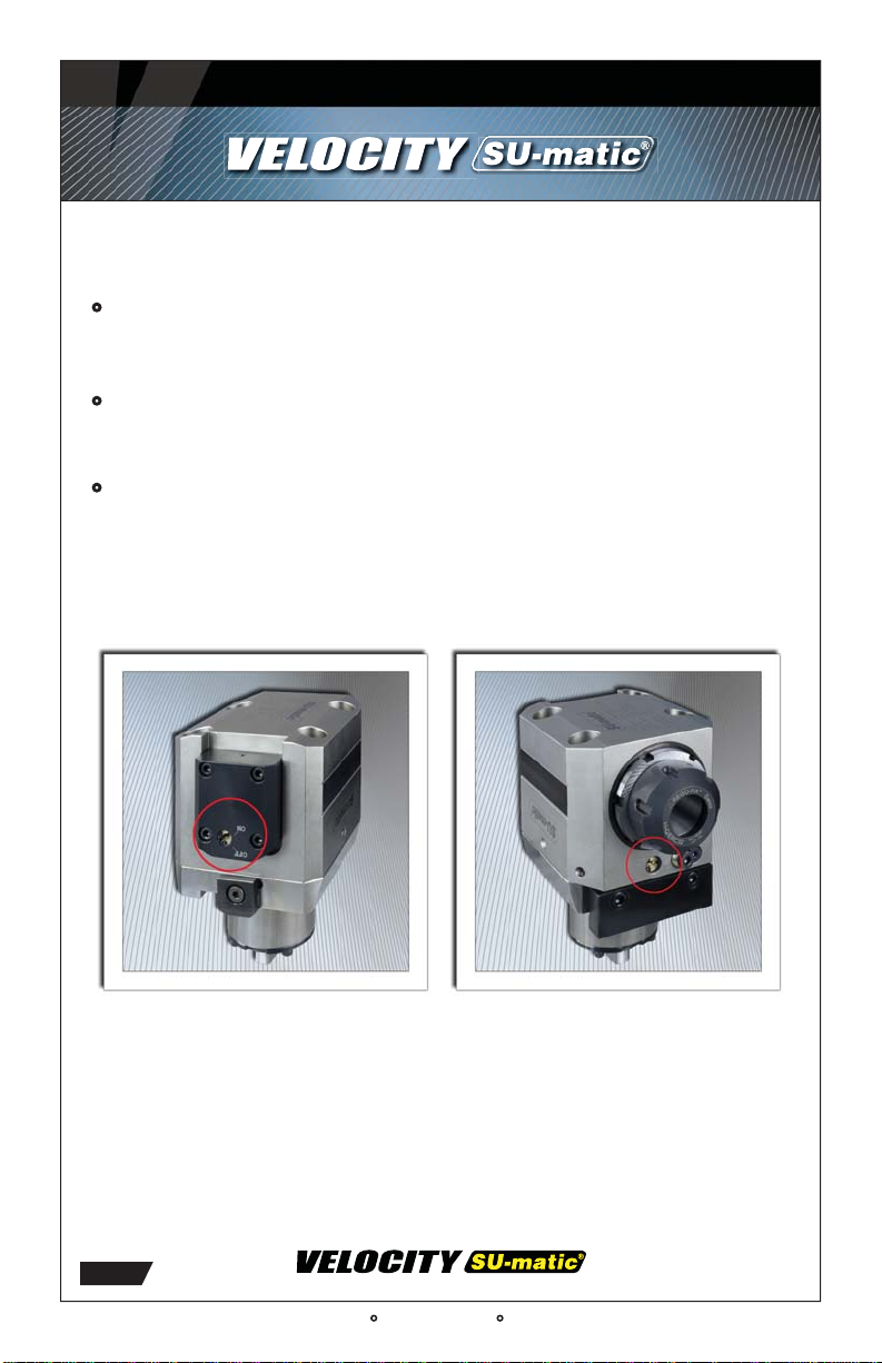
1) Loosen the bolt on the back mounting plate on the tool.
2) Place the tool in the turret station two positions above the
machining station and install tool mounting bolts - do not tighten
mounting bolts yet.
3XVKWRROIURPWKHIURQWWRÀUPO\SRVLWLRQWKHIURQWUHIHUHQFH
plate against the front of the turret face.
4) Firmly tighten the back mounting plate at the rear of the tool
against the back face of the turret.
5) Lightly tighten the UHDUPRXQWLQJEROWVÀUVW, then lightly tighten
the front mounting bolts.
6) Firmly tighten the UHDUPRXQWLQJEROWVÀUVWWKHQÀUPO\WLJKWHQ
the front mounting bolts.
7) Check tool alignment by indicating either the alignment
surface on the side of the tool, or indicating a test bar inserted
into the tool collet.
8) For further information, please consult the Okuma Operation
and Maintenance Manual.

4
Alignment
Bearing Pocket
Alignment
Bearing Pocket
Never
Move This
Screw!
Never
Move This
Screw!
n
Screw
o
Screw
n
Screw o
Screw
Tools are pre-aligned at the factory. If any adjustments are required,
Loosen screws , then adjust screws .
no
VELOCITY/SU-MATIC INSTRUCTION MANUAL
VELOCITYPRODUCTS.COM
VELOCITY / SU-matic
LT2000 Installation
Please consult the Okuma Operation & Maintenance Manual prior
to mounting tools.
LT2000 driven tools are pre-set at the factory to align the tool
output with the Z-Axis.
1) Place the tool in the turret station three positions above the
machining station.
2) Tighten tool mounting bolts in a diagonal sequence starting
with bolt closest to the alignment bearing.
3) Check tool alignment by indicating either the alignment
surface on the side of the tool, or indicating a test bar inserted
into the tool collet.
4) If minor adjustments are required, fasten the Velocity LT2000
VAF Alignment Fixture to the front or back of the tool as shown on
the following page.

VELOCITY/SU-MATIC INSTRUCTION MANUAL
VELOCITYPRODUCTS.COM
VELOCITY / SU-matic
LT2000 Tool Installation
LT2000 VAF Alignment Fixture
5) Loosen the tool mounting bolts, then align tool to the Z-Axis
using the screws shown in red above.
6) If there is not enough play to allow alignment, loosen screw n
on the previous page, then loosen screw o, then align tool using
the screws shown in red above.
7) Firmly tighten mounting bolts.
5HPRYH9$)À[WXUHIURPWRRODQGXVHRQRWKHU/7WRROV
as needed.
Fasten LT2000 VAF Alignment fixture
to tool using these two screws.
Make any necessary tool alignment
adjustments using these two screws.
VAF LT2000
Alignment Fixture
VELOCITYPRODUCTS.COM
5

6
VELOCITY/SU-MATIC INSTRUCTION MANUAL
VELOCITYPRODUCTS.COM
VELOCITY / SU-matic
LT2000 Tool Installation
LT2000 VAF Alignment Fixture

7
VELOCITY/SU-MATIC INSTRUCTION MANUAL
VELOCITYPRODUCTS.COM
1,450 PSI high pressure axial internal
coolant tool with switch on back
of tool allowing for dry running
operation.
VELOCITY / SU-matic
Coolant Tool Instructions
All
VELOCITY / SU-matic
internal coolant tools require 30
PLFURQFRRODQWÀOWUDWLRQQRPLQDOPLFURQFRRODQWÀOWUDWLRQ
absolute*.
Cross/Radial coolant through tools cannot be run dry!
Operating cross/radial coolant through tools without coolant will
quickly damage tool seals and bearings*.
1,450 psi Face/Axial coolant through tools are equipped with
a switch on the back of the tool that allows the tool to be run dry.
This switch completely disengages the internal coolant seals from
the tool spindle allowing the tool to be run dry without damaging
the tool.
* )DLOXUHWRXVHFRRODQWÀOWUDWLRQDQGLQWHUQDOFRRODQWDVGHVFULEHGDERYHYRLGVWKHWRROZDUUDQW\
1,450 PSI high pressure axial internal
coolant tool with switch on front
RIWRROIRUGLUHFWLQJFRRODQWÁRZ
between internal coolant and
external coolant.

8
VELOCITY / SU-matic
Boring Bar Holders
VELOCITY / SU-matic
boring bar holders are shipped with
coolant through plates installed. Extra nozzle plugs are included
with the tool. If
the tool is to be
run with internal
coolant only,
replace the
nozzles with the
nozzle plugs. If
the holder is
to be run with
external coolant
only, remove
the coolant
plate and plug
hole nwith the
screw located in
hole o(labeled
"Parking Screw").
The same
procedure is
used with both single and double boring bar holders. Certain
VELOCITY / SU-matic
boring bar holders are equipped with
DVZLWFKWRUHJXODWHWKHÁRZRIFRRODQWEHWZHHQLQWHUQDODQG
external nozzles.
VELOCITY / SU-matic
Cutting Tool Installation
A spindle locking wrench must always be used in conjunction
with the collet nut wrench to ensure that the driven tool spindle
is locked when installing cutting tools. Failure to use the spindle
wrench could result in damage to the driven tool bearings and
drive tang, and also to the turret.
VELOCITY/SU-MATIC INSTRUCTION MANUAL
VELOCITYPRODUCTS.COM
1
2

9
VELOCITY / SU-matic
Adjustable Tool
Special Instructions
Please consult the Okuma Operation & Maintenance Manual
prior to mounting tools.
When an adjustable tool is used for milling, the maximum cutter
diameter is 1/2 the maximum drill diameter for the tool.
VELOCITY/SU-MATIC INSTRUCTION MANUAL
VELOCITYPRODUCTS.COM

10
VELOCITY/SU-MATIC INSTRUCTION MANUAL
VELOCITYPRODUCTS.COM
VELOCITY / SU-matic
Capto Tools
VELOCITY / SU-matic
Capto live tools use a SU-matic
designed, sealed draw tube mechanism.
All
VELOCITY / SU-matic
Capto tools are internal coolant
and UHTXLUHPLFURQFRRODQWÀOWUDWLRQQRPLQDOPLFURQ
FRRODQWÀOWUDWLRQDEVROXWH
When installing a Capto cutting unit:
1)6HWDWRUTXHZUHQFKWRWKHQXPEHUVSHFLÀHGRQWKHWRRO
2) Push down hard on the torque wrench to make sure the hex
drive is fully engaged in the hex socket. Do not use a ball tipped
hex drive as this may damage the Capto mechanism.
3) If the seal does not snap back when the torque wrench is
removed, wiggle the Capto cutting unit and the seal will snap
back into a closed position. The spring loaded seal must snap
back into a closed position before the tool is run.
Spring loaded draw tube
sealing mechanism. Hex socket.
Use torque
wrench to
install
Capto
cutting unit.
Torque specication
is shown on tool.

11
VELOCITY/SU-MATIC CAPTO®TOOLING
VELOCITY / SU-matic
Capto Tools
VELOCITY / SU-matic
Capto tools use a Sandvik Capto
clamping unit installed in the "Right" orientation as standard. If
the "Left" orientation is required, the tool holder can be ordered
in advance with "Left" orientation, or the clamping unit can be
easily rotated by using a Sandvik CC-ET-01extracting tool (C4)
and a C4-WDT-02 withdrawal tool. Please contact Velocity for
assistance if clamping unit rotation is required.
Right Orientation Left Orientation

12
VELOCITY/SU-MATIC CAPTO®TOOLING
VELOCITY / SU-matic
Capto Tools
The example below shows a main/sub spindle Capto OD
holder. The orientation of the Capto clamping units can be
adjusted so that the Capto cutting units are optimized for chip
removal, insert maintenance, or uniformity of cutting units as
shown on the next page. The "Right" orientation is standard.
Right Orientation
Left Orientation

13
VELOCITY/SU-MATIC CAPTO®TOOLING
VELOCITY / SU-matic
Capto Tools
The examples below show the options available on an Okuma
LT2000 twin turret, main/sub spindle lathe for the orientation
of the Capto clamping units on the tool holders, and also the
choices available for the Capto cutting units.
RIGHT
LEFT RIGHT
LEFT
LEFT
RIGHT LEFT
RIGHT
LEFT
LEFT LEFT
LEFT
This example shows the
Capto clamping units
oriented on the tool holders
for chip optimization. The
Capto cutting units were
chosen to ensure that the
chips all drop in the same
direction.
This example shows
the Capto clamping
units oriented on the tool
holders optimized for insert
monitoring. The Capto
cutting units were chosen so
that the inserts are all facing
the front of the machine.
This example shows the
Capto clamping units
oriented on the tool holders
so that only one type of
Capto cutting unit is required.

14
VELOCITY/SU-MATIC CAPTO®TOOLING
VELOCITYPRODUCTS.COM
Extracting
Tool
Withdrawal
Tool
VELOCITY / SU-matic
Capto Tools
If the Capto clamping unit needs to be rotated, the proper
extracting tool and withdrawal tool must be used.
Capto Size Withdrawal Tool Extracting Tool
C3 C3-WDT-01M CC-ET-01
C4 C4-WDT-02
C5 C5-WDT-02
CC-ET-02C6 C6-WDT-02
C8 C8-WDT-02
Capto Clamping Unit Rotation Instructions
Clean the CC sleeve and the cavity in the CC clamping unit.
Slightly grease the external diameter of the CC sleeve.
Carefully replace the sleeve (indexed 180° from the previous
position) into the cavity. Gently tap down on the CC sleeve and
positioning pins until the CC sleeve reaches the face of the CC
clamping unit housing.
Lock the CC sleeve with (4) Torx screws.

INSTRUCTION MANUAL
A Complete Lineup of In-Stock Lathe Tooling for Okuma Two Year Warranty*
Velocity Products 350 Electronics Blvd, Huntsville, AL 35824 256-258-5549
*Warranty voided if internal coolant tools are used without coolant and coolant filtration.
Exceeding specified maximum cutting tool sizes voids warranty.
© Velocity Products Specifications subject to change without notice SU-matic Instructions 5.2018
OKUMA
O
KUM
A
ONLY FOR