Velocity VDOT-ASD-400 User manual

!
VDOT-ASD-400
Aspirating Smoke Detector
User’s Manual
!

VDOT-ASD-400 Aspiration Detector Velocity Detection
2
VDOT-ASD-400 Aspirating Smoke Detector User’s Manual V1
Content& &
Introduction*.............................................................................................................................................................*3!
Features*.....................................................................................................................................................................*3!
Specification*.............................................................................................................................................................*5!
Sampling*Pipework*Design*.................................................................................................................................*8!
Considerations+...............................................................................................................................................................................................+8!
Design+Guidelines+......................................................................................................................................................................................+11!
Installation*.............................................................................................................................................................*13!
Mechanical+Installation+...........................................................................................................................................................................+13!
Electrical+Installation+...............................................................................................................................................................................+15!
Front*Panel*.............................................................................................................................................................*20!
Control+............................................................................................................................................................................................................+21!
Display+............................................................................................................................................................................................................+21!
Parameter+Setup+.........................................................................................................................................................................................+25!
Parameter*Functions*...........................................................................................................................................*27!
Commissioning*......................................................................................................................................................*32!
Commissioning+Check+List+.....................................................................................................................................................................+32!
Maintenance*...........................................................................................................................................................*34!
Appendix*.................................................................................................................................................................*38!
Pipe+Scan+.......................................................................................................................................................................................................+38!
Zone+Relay+Board+.......................................................................................................................................................................................+41!
!
!

VDOT-ASD-400 Aspiration Detector Velocity Detection
3
VDOT-ASD-400 Aspirating Smoke Detector User’s Manual V1
Introduction
VDOT-ASD-400 is aspirating smoke detectors especially developed by ASD prevent CO., Ltd. for large
open space very early warning fire detection.
Due to the nature of aspirating smoke detection systems, the air samples from all the individual
sampling pipes are drawn into one central detection unit causing the smoke particles to mix, making
the identification area difficult to determine. However, one of the advantages of VDOT-ASD-400 is
that it has four independent aspirators; each aspirator is connected to its own pipe inlet. Therefore,
it can easily identify the smoke origin simply by the control of each aspirator on and off to see which
pipe has the highest smoke level. This ASD patented pipe scan process identifies the pipe that
contains the most smoke, extremely useful when using the four-pipe aspirating smoke detector. This
multi-pipe system is designed to protect large areas, the pipe scan system can quickly and
automatically identify the individual pipe, reducing the search area down drastically to a quarter of
the protected area, making the fire search much easier. Features
Features!
ASD uses high power, short wavelength blue LED as the detection light source. It is very sensitivity
to small smoke particles generated during the incipient stage of a fire, at which time remaining
invisible to human eyes. The highest alarm sensitivity of ASD high sensitivity smoke detector is
0.005%/m, which is 1000 times more sensitive than a conventional point type smoke detector.
l Alarm&Sensitivity&Range:&0.005~20%/m&
l Four&Alarm&Levels&
l Automatic&and&Manual&Pipe&Scan&

VDOT-ASD-400 Aspiration Detector Velocity Detection
4
VDOT-ASD-400 Aspirating Smoke Detector User’s Manual V1
l Up&to&4x100m&Pipe&Length*&(4x10&sampling&holes)&
l Up&to&4x25&Sampling&Holes*&(4x60m&sampling&pipe&length)&
l 7&Relays&Outputs&on&Termination&Board&
l 16&Relays&on&Zone&Relay&Board&(Optional)&
l 3&in&1&Control/Display/Programmer&Front&Panel&
l RS485&Network&
l Support&Modbus&RTU&Open&Protocol&
&
*Note: Maximum pipe length and maximum number of sampling holes cannot be achieved at the
same time. When maximum pipe length is the major design consideration, the number of sampling
holes must be reduced. On the other hand, when maximum number of sampling holes is the major
design consideration, the pipe length must be reduced.
!

VDOT-ASD-400 Aspiration Detector Velocity Detection
5
VDOT-ASD-400 Aspirating Smoke Detector User’s Manual V1
Specification!
Smoke Detection Principle
- Forward Light Scattering Mass Detection
- High Power Blue LED
Smoke Sensitivity
- Smoke Detection Range: 0.001~25%/m
- Alarm Sensitivity Range: 0.005~20%/m
Sampling Pipe
- Material: ABS/UPVC
- OD: 25mm
Maximum Pipe Length and Sampling Holes
- EN54-20 Class A: Maximum 40 holes totally
" 4x100m (4x10 holes)
" 3x100m (3x13 holes)
" 2x100m (2x20 holes)
- EN54-20 Class B: Maximum 60 holes totally
" 4x100m (4x15 holes)
" 3x80m (3x20 holes)
" 2x60m (2x25 holes)
- EN54-20 Class C: Maximum 100 holes totally
" 4x60m (4x25 holes)
*Note
:
Please refer to Velocity ASD Design manual for the relationship between pipe length and the
number of sampling holes.
The ASDFlow air sampling pipe network design tool can be used to calculate the maximum
transport time and sampling hole sensitivity.
&
Important Note:
Operation of the Detector beyond 12%/m obscuration is not allowed per the National Fire
Alarm Code (NFPA 72) guidelines.

VDOT-ASD-400 Aspiration Detector Velocity Detection
6
VDOT-ASD-400 Aspirating Smoke Detector User’s Manual V1
Alarm Levels and Time Delay
- Alert (0~60 sec.)
- Action (0~60 sec.)
- Fire-1 (0~60 sec.)
- Fire-2 (0~60 sec.)
Environment Smoke Learning
- 24hours, 365days Non-Stop Smoke Background Level Learning
Flow Detection
- Detection Principle: Heat Mass Detection
- Pipe Flow Normalize to 100%
- Flow High and Flow Low Fault
- Adjustable Flow Detection Sensitivity
- Adjustable Flow Fault Threshold
Relay Output
- 7 Relays on Termination Board (Configurable)
- Rating: 2A@30 VDC
General Purpose Inputs
- 8xGPIs (Configurable)
- GPI Functions: RESET/ISOLATE/SILENCE/TEST/MAINS FAULT/BATT. FAULT/POWER
FAULT/SENSITIVITY MODE 1/SENSITIVITY MODE 2/SCAN/UDI-1/UDI-2/UDI-4/UDI-5
*Note: UDI, User Defined Input
Communication
- RS-485 Network
- Maximum number of devices on Network: 250
- Built in repeater
- Maximum cable length between two adjacent devices: 1.2km
- Support Modbus RTU open protocol
Control
- <Reset>, <Isolate>, <Silence> & <Test> buttons

VDOT-ASD-400 Aspiration Detector Velocity Detection
7
VDOT-ASD-400 Aspirating Smoke Detector User’s Manual V1
Display
- 20 segment smoke level bargraph
- 6-digits Numerical LEDs Display
" Real Time Smoke Level
" Real Time Airflow Level
" Device Address
" Active Event & Codes
- 4 Fire Alarm Indicators
" Alert, Action, Fire 1, Fire 2
- 4 Fault Indicators
" Detector, Airflow, System, Auxiliary
- Isolated indicator
- Beeper
Programmer
" Access Password Controlled
" Bargraph and 6-digits 7-Numerical LEDs display the function.
" <Func.> <ï><ð> <+> <-> <↵> buttons to change settings.
Event Logs
- Number of Events: 25000
- Event Type: Alarm/Fault/Operation/Smoke/Flow/Auxiliary Gas Sensors
Operating Conditions
- Ambient Temperature: 0~40 ℃
- Sampling Air Temperature: -20~60 ℃
- Humidity: 10~95% RH Non-Condensing
Power
- 24 ±4.8 Vdc
- 620mA (Nominal, Aspirator speed 5)
- 860mA (Maximum, Aspirators speed 10, Alarm Status)
Dimension
- Length=415mm
- Width=259mm
- Height=108mm
Weight
- Net Weight:5.2kg

VDOT-ASD-400 Aspiration Detector Velocity Detection
8
VDOT-ASD-400 Aspirating Smoke Detector User’s Manual V1
Sampling!Pipework!Design!
Aspirating system design is inherently simple. It is often possible to achieve good system
performance with very simple installations. There are however a few rules, which must be adhered
to, and these rules are equally applicable to all aspirating systems. The information contained in this
manual is intended as an overview only. For further information please see the complete Velocity
ASD Design Manual.
Considerations
o Primary!Detection!Sampling!Systems!
Are usually arranged to monitor the flow of air movement by the use of pipework and air sampling
points mounted directly in the airflow. This type of system is usually regarded as supplementary to
other forms of detection due to its limited response capability once the air movement ceases.
In such a system when monitoring a single point of supply or extract, its system sensitivity may be
directly related as equal to the sensitivity of the central detector due to the cumulative effect. In the
case of a system monitoring more than one point of supply / extract then the system sensitivity will
only be determined in discussions with the manufacturer or his representative.
Always locate the sampling points in a position to which smoke may reasonably be expected to
travel. This may sound obvious, but, for example, do not expect ceiling mounted sampling points to
operate satisfactorily if air flow prevents the cool smoke from an incipient fire from reaching ceiling
level. In this instance it is usually better to locate the sampling pipes directly in the airflow (for
example in an air conditioning unit air intake). There is no substitute for carrying out smoke tests
prior to installation of pipes to indicate suitable sampling point location.
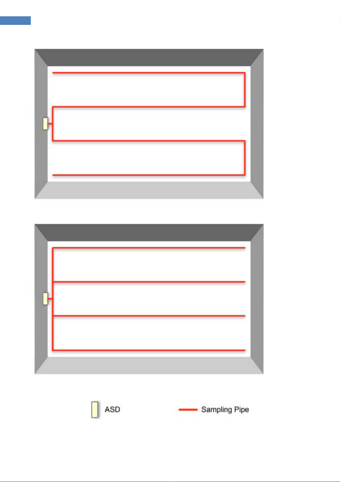
o Secondary!Detection!Sampling!Systems!
Are arranged such that the air sampling points are sited and spaced as if they are point type smoke
detectors. They can be positioned to satisfy NFPA 72, NFPA 76, BS 5839-1, BS 6266 and local fire
code requirements when the calculated relative sensitivity per air sampling hole equates to a point
detector. See Relative Sensitivity below.
o Maximum!Permissible!Transport!Time!
The time taken for a system to transport a sample from a protected area should not exceed 120
seconds (2 minutes). Transport times in excess of this must be the subject of a variation. Shorter

VDOT-ASD-400 Aspiration Detector Velocity Detection
9
VDOT-ASD-400 Aspirating Smoke Detector User’s Manual V1
maximum transport times may be desirable in certain applications and should be specified as part
of the risk assessment. For example, Class A ASD systems are generally designed with transport
times of less than 60 seconds.
Maximum transport time can be directly affected by the installed sample pipe design, see the
following Figures. The 4-branch design will provide the shortest transport time.
Single branch system

VDOT-ASD-400 Aspiration Detector Velocity Detection
10
VDOT-ASD-400 Aspirating Smoke Detector User’s Manual V1
Two branch system
Four branch system
o Balance!

VDOT-ASD-400 Aspiration Detector Velocity Detection
11
VDOT-ASD-400 Aspirating Smoke Detector User’s Manual V1
Balance is generally expressed as a percentage. If all the sample points have the same amount of air
entering each sample hole then this is invariably described as a system with 100% balance.
o Relative!sensitivity!
The relative sensitivity of each air-sampling hole (assuming that all sampling points have been
calculated for an equivalent sensitivity i.e. 100% balance) can be calculated as a simple function of
the detector sensitivity and the number of sample points. For example, a 0.1% high sensitivity
detection device connected to pipe-work containing 40 equivalent air sampling points can be
regarded as a 4%/m system which can be considered as a Class C sensitivity system. Unless
otherwise stated in approval documentation a figure of better than 5%/m sensitivity per hole may
be applied.
Design Guidelines
l The ideal diameter of sampling pipes is OD: 25mm / ID: 21mm. Other sizes will often work but
will provide different response times.
l Maximum pipework limitation
The limitation of each pipe inlet of VDOT-ASD-400 when the aspirator speed set to 10 is 100m
pipe length with up to 18 holes alone the pipe (maximum pipe length) or 60m pipe length with
up to 25 holes along the pipe (maximum holes) under the requirement of 120s maximum
transport time. There are four pipe inlets for VDOT-ASD-400, so the total maximum pipe length
is 4x100m/4x18holes or 4x60m/4x25holes.
- It is not possible to maximize the pipe length and the number of sampling points at the
same time. To maximize the pipe length, the number of sampling holes must be reduced.
On the other hand, to maximize the number of the sampling holes on the pipe, the pipe
length must be reduced.
l Ideally, if the total length of sampling pipe is greater than 50 meters, then branch pipes should
be used. When using branched sampling pipes, care should be taken to achieve a reasonable
degree of balance (say within 10% of airflow) to ensure even suction from the pipes.
l Sampling pipes must have capped ends. The end cap should be drilled with a sampling hole
normally between 4 or 6mm diameter and free from burrs.
l Sampling holes should normally be 2-4mm diameter or as calculated by ASDFlow and free from
burrs.
l This guide holds true for average sampling pipe lengths, but if using long pipes (typically more
than 60 meters total), performance may be improved by making the sampling holes near the
ends slightly larger than those nearer the detector.
l Although by no means essential, it must be recommended that if in doubt, ASDFlow be used to

VDOT-ASD-400 Aspiration Detector Velocity Detection
12
VDOT-ASD-400 Aspirating Smoke Detector User’s Manual V1
ensure that transit times, balance of suction and individual sampling point sensitivity are
within desired limits.
l System Sensitivity: The recommended maximum number of sampling holes on the pipework to
achieve desired relative sampling hole sensitivity is as follows
- Class A: 40 holes
- Class B: 60 holes
- Class C: 100 holes
l In Consideration of both maximum pipework and system sensitivity, the recommendation of
pipe length and number of holes to achieve different sensitivity of VDOT-ASD-400 are
- EN54-20 Class A: Maximum 40 holes totally
" 4x100m (4x10 holes)
" 3x100m (3x13 holes)
" 2x100m (2x20 holes)
- EN54-20 Class B: Maximum 60 holes totally
" 4x100m (4x15 holes)
" 3x80m (3x20 holes)
" 2x60m (2x25 holes)
- EN54-20 Class C: Maximum 100 holes totally
" 4x60m (4x25 holes)
!

VDOT-ASD-400 Aspiration Detector Velocity Detection
13
VDOT-ASD-400 Aspirating Smoke Detector User’s Manual V1
Installation!
Note: It is recommended that the installation is carried out by suitably experienced and trained
personnel.
Mechanical Installation
Dimensions
l The mounting holes in each corner are used to mount the device on the wall. It is
recommended the device is 1.5m above the floor. The device location should be
considered for easy access and suitable for the temperature and humidity operating
condition mentioned in the specification.
l Ensure that when the detector is fitted to the wall there is enough space on the right-
hand side to allow the opening of the front panel.

VDOT-ASD-400 Aspiration Detector Velocity Detection
14
VDOT-ASD-400 Aspirating Smoke Detector User’s Manual V1
Cable entries are also provided on the side and bottom. It should be noticed that some cable
entries are non-cut through holes, a punch using a screwdriver and hammer or a proper tool
are needed to open the entry holes.
Sampling&pipes&
Sampling pipes should be made from a non-hazardous material and should be clearly identified.
Typical sampling pipes used in air sampling systems are ABS/uPVC pipes with 25mm OD. The pipes
should be marked with air sampling or aspirating smoke detection pipe to identify its usage. Red
pipe is recommended for it is a fire alarm system.
In some cases, high temperature or corrosion is a concern, metal or other materials suitable
materials for that environment can be used.
When drilling holes in the sample pipes, or cutting off lengths of pipe, ensure that all swarf and
debris is removed from the pipe.

VDOT-ASD-400 Aspiration Detector Velocity Detection
15
VDOT-ASD-400 Aspirating Smoke Detector User’s Manual V1
Electrical Installation
Above picture is the internal view of the VDOT-ASD-400. All the electrical connections should be
made to the removable connectors on the termination board or the relay board if it equipped.
Cables&
Power cable should be 2.0mm2-2C of sufficient current carrying capacity.
Control cable should be 0.75mm2 strands cable.
RS485 network should be 24AWG twisted pair shielded cable.
High%Sensitivity%Smoke%Detector
Zone%Relay%Board%(Optional)
Termination%Board
Filter
Flow%Sensor%#1
Aspirator%#1
Flow%Sensor%#2
Flow%Sensor%#3
Flow%Sensor%#4
Aspirator%#2
Aspirator%#3
Aspirator%#4

VDOT-ASD-400 Aspiration Detector Velocity Detection
16
VDOT-ASD-400 Aspirating Smoke Detector User’s Manual V1
Terminal&Connections&
VDOT-ASD-400 Termination Board
o Power!Supply!Connections!
There are two 24Vdc power terminals on the termination board. One must be connected to a
24±20% (19.6~28.8) DC Power Supply. The device may be powered by any EN54-4 compliant
monitored 24DC power supply of sufficient capacity.
o Relay!Connections!
There are 7 configurable relays on the termination board.
l Isolated (NO/NC)
l Fault (NO/NC)
l Alert (NO)
l Action (NO)
&
Important Note:
The required 24Vdc primary power and 24 hour standby power for the Detector must be
obtained locally from a means suitable for NFPA 72 applications.

VDOT-ASD-400 Aspiration Detector Velocity Detection
17
VDOT-ASD-400 Aspirating Smoke Detector User’s Manual V1
l Fire-1 (NO)
l Fire-2 (NO)
l Aux (NO)
Note: NO=Normally Open NC=Normally Closed Com=Common
The relay rating is 2A@30Vdc. If load connected is more than the relay rating, a transfer relay
suitable for the rating should be used.
Every relay has its indicator (LED) on board to indicate it’s on/off status. It’s easy for the user to
know the relay status and to trouble shoot if the connected device doesn’t go out properly.
All relays are configurable to one of the following functions: Alert, Action, Fire 1, Fire 2, Fault,
Isolate, and Auxiliary. The relay output function printed on the termination board is the factory
default setting. Users can change the relay function using the front panel display or the
Management computer Software to change the setting. However, the second relay, which
circuit is designed to normally closed to give a trouble signal when the device is powered off.
Care should be taken for the relay’s NO or NC connection when changing relay functions.
o GPI,!General!Purpose!Input!
There are eight General Purpose Input terminals on VDOT-ASD-400 termination board. Those inputs
are designed to monitor the status of the connected devices. The connected devices monitored by
the GPI can be just a button, a fault relay from the power supply, or even alarm relay from other
detector. Short circuit the pair of the input pins makes ASD to activate associated function defined
in the GPI settings. There are 16 possible functions falls in the following categories:
l Device Control: Reset, Isolate, Silence, Test, Scan,
The GPI terminal can be connected to a remote button, a control/output module of the fire
alarm system, or a PLC so those control function can be performed remotely, or by other
systems.
l Power Fault Monitoring: Mains Fault, Battery Fault, Power Fault
It is sometimes required by local code that the fault status of the mains and/or battery
condition of the detector’s power supply should be monitored. In this case, the ASD detection
device will signal a fault when the connected relay of power supply is activated. The ASD fault

VDOT-ASD-400 Aspiration Detector Velocity Detection
18
VDOT-ASD-400 Aspirating Smoke Detector User’s Manual V1
condition can then be monitored by a fire alarm system when its fault relay is connected the
fire alarm system input module.
l Sensitivity Change: Sensitivity Mode 1, Sensitivity Mode 2
In some applications, the detection area environment background smoke level is different in a
day. For example, in work hours the background smoke level is usually higher than the non-
working hours. Sometimes, outside pollutants go into the detection area can generate false
alarm. There are needs to decrease the sensitivity to prevent the false alarm or increase the
sensitivity to provide better protection in a daily basis or in certain situations. In this case, the
GPI can be connected to a button, a timer, a PLC or even a relay output of other ASD detector
sensing the pollutant level from outside, so that that sensitivity adjustment can be made
manually or locally.
l User Defined Device Monitoring: UDI-1, UDI-2, UDI-3, UDI-4, UDI-5
The UDI, User Defined Input is usually used to monitor the status (relay) of other detection device,
like gas sensors, temperature sensors, or other aspirating smoke detectors.
The GPI-1 on the VDOT-ASD-400 termination board is a monitored contact with a 10KΩ terminal
resistor connected at the factory. When the GPI-1 is used, the terminal resistor needs to be moved
to the end of the line. When the line connected to the GPI-1 is shorted, the device reports a GPI-1
alarm; when the line connected to the GPI-1 is open, the device reports a GPI-1 fault.
The GPI-2 on the VDOT-ASD-400 terminal board is an active input with monitoring contact, and is
disabled by default. To enable the GPI-2, mount both the P1 and P2 jumper selection to 2/3 PIN and
set the corresponding GPI function. When the external active input is disconnected for less than 3
seconds, the corresponding GPI-2 function is activated, and when the GPI-2 connection line is
disconnected or open for more than 6 seconds, the GPI-2 fault is reported.
!
o RS-485!
!
l Two RS-485 Terminals
l Built in RS-485 repeater, the cable length can be extended to next device for another
1.2km.
l RS-485 Network can be configured in closed loop for better communication reliability. The
communication can switch direction to communicate with devices behind the failure point
when there’s device failure, line break or line short circuit.

VDOT-ASD-400 Aspiration Detector Velocity Detection
19
VDOT-ASD-400 Aspirating Smoke Detector User’s Manual V1
l Computer Management System (a computer software) can monitor all devices on
network.
l SCADA/HMI/PLC systems capable of Modbus RTU open protocol can communicate with
ASD devices.
VDOT-NET64 Velocity Aspirating Network Configuration
!
D+
D-
S
D+
D-
S
D+
D-
S
D+
D-
S
偵測主機
D+
D-
S
D+
D-
S
D+
D-
S
D+
D-
S
偵測主機 偵測主機 偵測主機
D+
D-
S
D+
D-
S
D+
D-
S
D+
D-
S
偵測主機
D+
D-
S
D+
D-
S
D+
D-
S
D+
D-
S
偵測主機 偵測主機 偵測主機
AVA 通訊網路RS-485 連線架構
AVA 最大不超過250元件
24AWG-2P 單/雙隔離網接地線
ASD Device
24AWG Twisted Paired
Screened Cable
Closed Loop Connection
nection (Optional)
ASD Device
ASD Device
ASD Device
ASD Device
ASD Device
ASD Device
ASD Device
Maximum 250 devices on
one network
nection (Optional)

VDOT-ASD-400 Aspiration Detector Velocity Detection
20
VDOT-ASD-400 Aspirating Smoke Detector User’s Manual V1
Front!Panel!
The VDOT-ASD-400 front panel is a Control / Display /Programmer 3 in 1 LED display.
Bargraph LED
-20 segments
Power Indicator
Isolate Indicator
6-digits Numerical Display
Alarm Level Indicators
Fault Indicators
Control Buttons
Display Mode Indicator
Table of contents
Other Velocity Smoke Alarm manuals