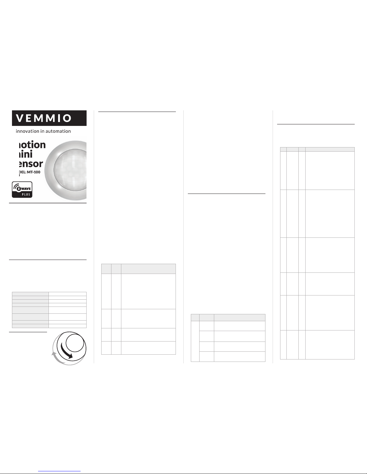
WWW.VEMMIO.COM
7Light
Sensor
Polling
Interva
Time
180 Valid Values: (60 – 36000), Unit: Sec-
ond, Prm. Size: 2 bytes
This Parameter can be set the light sen-
sor measure ambient illumination level
interval time. NOTE: This Value Must Be
less than Wakeup Interval Time
8 Lux
Level
Func-
tion
Enable
0Valid Values: (0 or 1), Prm. Size: 1 bytes
If this parameter is set to ‘1’, and when
Lux level less than the value define by
parameter #5, PIR detector will send
a BASIC_SET command frame (i.e.
BASIC_SET (value = parameter 3) to an
associated device and activate it. If Lux
Level greater than the value define by
parameter #5, PIR detector will not send
a BASIC_SET command frame.
9Ambient
illumina-
tion Lux
Level
Report
100 Valid Values: (0 – 255), Unit: Lux, Prm.
Size: 2 bytes
This parameter defines by how much
Lux Level must change, in lux, to be
reported to the main controller.
10 Led
Flash
Enable
1Valid Values: (0 or 1), Prm. Size: 1 byte
This parameter defines the Led on/off
enable. If this parameter is set to ‘1’, the
led blink will be enabled, the led will
flash once when motion sensor detect a
movement. Otherwise, the led will
be turned off always.
MULTILEVEL SENSOR
The Motion Mini Sensor supports ambient luminance measure-
ment, the scale is LUX. The settings of luminance sensor meas-
urement are listed in Advanced Configuration.
WAKEUP COMMAND CLASS
The motion detector stays in sleep status for the majority of
time in order to conserve battery life.
The minimum wakeup interval is 300s
The maximum wakeup interval is 16,777,200s (about 194 days)
Minimum interval is 60 second, values need to follow minimum
interval value - e.g. 360, 420, 480…
The default value is 12 hours.
BATTERY CHECK COMMAND
The users can also check the battery status of the Motion Mini
Sensor by sending BATTERY_GET command. Once the motion
detector receivers the command, it will return BATTERY_RE-
PORT command. The motion detector will send BATTERY_LEV-
EL = 0xFF command to the Z-Wave Controller to inform that
the motion detector is in dead battery status, otherwise BAT-
TERY_LEVEL value range is 0% to 100%.
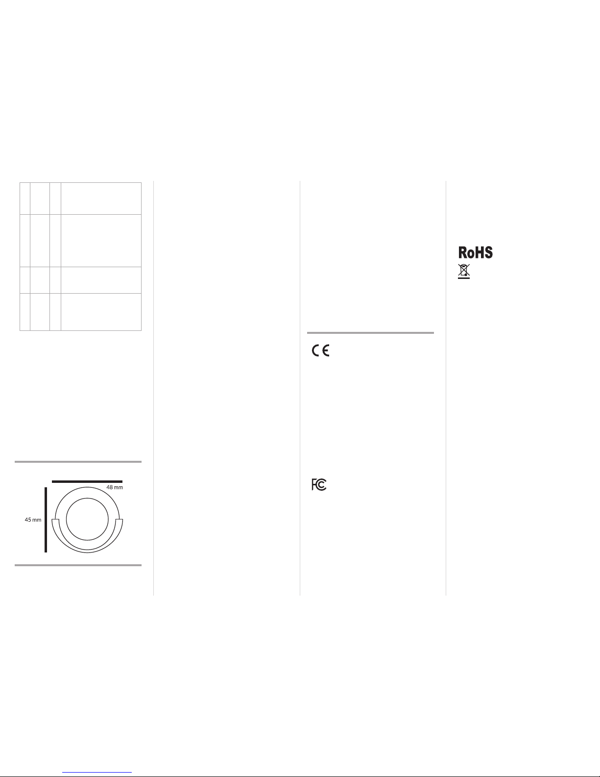
DIMENSIONS
WARRANTY
This Limited Warranty applies to physical goods, and only for
physical goods, purchased from Vemmio (the “Physical Goods”).
This Limited Warranty of Vemmio, applies to products manufac-
tured and distributed by Vemmio.
PRODUCTS COVERED AND DURATION OF WARRANTY
Warranty Period: 12 months for business customer and 24
months for individual customer from the date of purchase.
The product purchased shall be free from defects in material
and workmanship from the date of purchase.
This Limited Warranty covers any defects in material or work-
manship under normal use during the Warranty Period.
PRODUCTION STATUS
Each product is manufactured from new parts.
TERMS OF THE WARRANTY
Vemmio warrants that the product you have purchased from
Vemmio or a Vemmio’s authorized reseller is free from defects
in materials and workmanship under normal use during the
warranty period. The warranty period begins on the day of pur-
chase. The warranty extends only to the original purchaser. It
is not transferable to anyone who subsequently purchases the
product from the original purchaser.
During the Warranty Period, Vemmio will repair or replace (at
the sole discretion of Vemmio), at no charge, products or parts
of a product that proves defective. Once the defected product,
during the guarantee period, is returned, it will be repaired or
replaced no later than within 30 days. The warranty period is
extended by the amount of days it has taken to repair or replace
the product. All used elements changed under the guarantee
become the property of Vemmio. The warranty period for re-
placed elements expires on the same date as the original war-
ranty period for the product. There is a possibility that it will not
be feasible to repair or replace the product ( for example when
the product is no longer a part of Vemmio’s offer). Should this
happen, Vemmio will repair/replace the product with parts/
product of similar technical characteristics. Such procedure
will result in fulfilling Vemmio’s warranty obligation against the
customer. It is not possible to have money returned by Vemmio
for the purchased product. Warranty claim rated by Vemmio as
unwarranted will be charged for handling and servicing costs.
Vemmio may reject a warranty claim if:
• the product has not been operated according to its intended
purpose and the user manual
• the returned product is incomplete
• the cause of insufficient operation is other than a material or
production defect
• warranty date has expired or if the customer can not provide
proof of purchase.
The Limited Warranty extends only to products purchased from
Vemmio or a Vemmio’s authorized reseller. The Limited War-
ranty does not extend to any product that has been damaged or
rendered defective (a) as a result of accident, misuse or abuse;
(b) as a result of an act of God; (c) by operation outside the us-
age parameters stated in the user manual; (d) by the use of parts
not manufactured or sold by Vemmio (e) by modification of the
product; (f) as a result of war or terrorist attack; or (g) as a result
of service by anyone other than Vemmio or a Vemmio’s author-
ized service center.
EXCEPT AS EXPRESSLY SET FORTH IN THIS WARRANTY,
VEMMIO MAKES NO OTHER WARRANTIES EXPRESSED
OR IMPLIED, INCLUDING ANY IMPLIED WARRANTIES OR
MERCHANTABILITY AND FITNESS FOR A PARTICULAR PUR-
POSE. VEMMIO EXPRESSLY DISCLAIMS ALL WARRANTIES
NOT STATED IN THIS LIMITED WARRANTY. ANY IMPLIED
WARRANTIES THAT MAY BE IMPOSED BY LAW ARE LIMIT-
ED TO THE TERMS OF THIS EXPRESS LIMITED WARRANTY.
LIMITED WARRANTY STATEMENT
VEMMIO is not liable for any damages caused by the product
or by the failure of the product to perform, including any lost
profits, lost savings, incidental damages, or consequential dam-
ages. VEMMIO is not liable for any claim made by a third party
or made by you for a third party.
This limitation applies whether damages are sought, or a claim
made, under this warranty or as a tort claim (including negli-
gence and strict product liability), a contract claim, or any other
claim. This limitation can not be waived or amended by any per-
son. This limitation of liability will be effective even if VEMMIO
or an authorized VEMMIO’S representative has been advised
by you of the possibility of any such damages.
HOW TO OBTAIN WARRANTY SERVICE?
Please contact us first through support@vemmio.com for ad-
vice because we are very often able to resolve issues/problems
without the need for warranty claim.
For a defect during the warranty period, you will need a proof of
purchase. Contact your place of purchase or a Vemmio’s author-
ized service center. Return the defective item, freight and insur-
ance prepaid, in the original packaging to your place of purchase.
Vemmio is not responsible for any loss or damages incurred in
shipping. A Vemmio Failure Analysis/Test Engineer or a Vem-
mio’s authorized reseller must validate all warranty claims.
WHAT IS NOT COVERED BY THIS WARRANTY?
Product purchased from anyone other than Vemmio or a Vem-
mio’s authorized reseller.
Routine cleaning or normal cosmetic and mechanical wear.
Damage from misuse, abuse or neglect including ingress of wa-
ter, dust or damage from dropping.
Damage from use outside the product’s usage or storage pa-
rameters.
Damage from use of parts not manufactured or sold by Vemmio.
Damage from modification or incorporation into other products.
Damage from repair or replacement of warranted parts by a
service provider other than a Vemmio’s authorized service
provider.
Damage from failure to perform preventative maintenance
as imposed by the application environment (such as recurrent
cleaning in dusty surroundings).
DECLARATION OF CONFORMITY
The manufacturer Vemmio Sp. z o.o. declares under sole respon-
sibility that the product:
Marketing model: Motion Mini Sensor
Regulatory model: MT-100
Brand name: Vemmio
is in conformity with the Low Voltage Directive 2009/95/EC,
EMC Directive 2004/108/EC, R&TTE Directive 1995/5/EC and
carries the CE marking accordingly.
The following harmonized standards were applied:
R&TTE (1995/5/EC)
EN 300 220-1: V2.4.1
EN 300 220-2: V2.4.1
EMC (2004/108/EC)
EN 301 481-1: V1.9.2
EN 301 489-3: V1.6.1
LVD (2006/95/EC)
EN 60950-1:2006 + A11:2009 + A1:2010 + A12:2011
Changes of modification not expressly approved by Vemmio Sp.
z o.o. for compliance could void the user’s authority to operate
the equipment.
FCC INTERFERENCE STATEMENT
This equipment has been tested and found to comply with the
limits for a Class B digital device, pursuant to Part 15 of the FCC
Rules. These limits are designed to provide reasonable protec-
tion against harmful interference in a residential installation.
This equipment generates, uses and can radiate radio frequency
energy and, if not installed and used in accordance with the
instructions, may cause harmful interference to radio com-
munications. However, there is no guarantee that interference
will not occur in a particular installation. If this equipment does
cause harmful interference to radio or television reception,
which can be determined by turning the equipment off and on,
the user is encouraged to try to correct the interference by one
of the following measures:
• Reorient or relocate the receiving antenna.
• Increase the separation between the equipment and receiver.
• Connect the equipment into an outlet on a circuit different
from that to which the receiver is connected.
• Consult the dealer or an experienced radio/TV technician
for help.
This device complies with Part 15 of the FCC Rules. Operation is
subject to the following two conditions:
1. This device may not cause harmful interference, and
2. This device must accept any interference received, including
interference that may cause undesired operation.
FCC Caution: Any changes or modifications not expressly ap-
proved by the party responsible for compliance could void the
user’s authority to operate this equipment.
This transmitter must not be co-located or operating in conjunc-
tion with any other antenna or transmitter.
IN ACCORDANCE WITH ROHS 2011/65/EU
WARNING
Do not dispose of electrical appliances as unsorted municipal
waste, use separate collection facilities. Contact your local gov-
ernment for information regarding the collection systems avail-
able. If electrical appliances are disposed of in landfills or dumps,
hazardous substances can leak into the groundwater and get
into the food chain, damaging your health and well-being.
When replacing old appliances with new once, the retailer is
legally obligated to take back your old appliance for disposal at
least for free of charge.
Please note: Vemmio provides this publication “as is” without
warranty of any kind, either express or implied, including, but
not limited to implied warranties of merchantability or fitness
for a particular purpose. The published information in the man-
ual is subject to change without notice. Vemmio reserves the
right to make changes in the product design, layout, and driver
revisions without notification to its users. This version of the
installation guide supersedes all previous versions.
Although Vemmio has attempted to ensure the accuracy of the
content of this manual, it is possible that this document may
contain technical inaccuracies, typographical, or other errors.
Vemmio assumes no liability for any error in this publication,
and for possible damages, whether direct, indirect, incidental,
and consequential or otherwise, that may result from such er-
ror, including, but not limited to loss of data or profits.