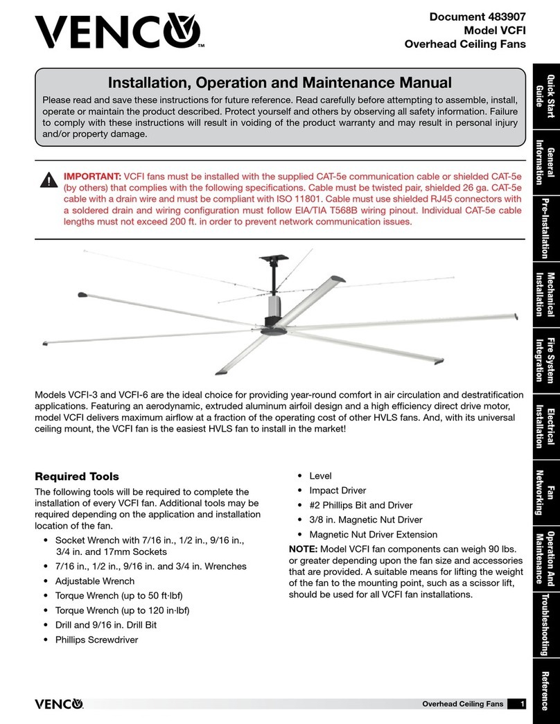
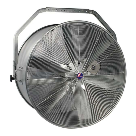
VENCO VD-EX User manual

INSTALLATION – OPERATION -
MAINTENANCE USER MANUAL
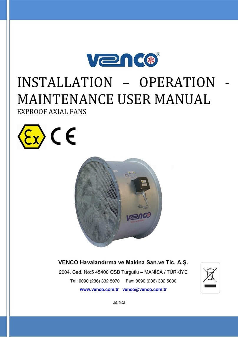
WALL MOUNTED EXPROOF AXIAL FANS
VENCO Havalandırma ve Makina San.ve Tic. A.Ş.
2004. Cad. No:5 45400 OSB Turgutlu – MANİSA / TÜRKİYE
Tel: 0090 (236) 332 5070 Fax: 0090 (236) 332 5030
www.venco.com.tr [email protected].tr
20
1
9
.
1
0
2019.02

2019.10 1 / 8
INDEX
1. INTRODUCTION ..................................................................................................................................... 1
2. GENERAL IDENTIFICATION OF DEVICE TYPE and MODEL ............................................................... 2
3. TECHNICAL DATA ................................................................................................................................. 2
4. TECHNICAL SPECIFICATIONS ............................................................................................................. 3
5. INSTALLATION ....................................................................................................................................... 3
6. OPERATION ........................................................................................................................................... 7
7. HANDLING & STORAGE ........................................................................................................................ 7
8. MAINTENANCE ...................................................................................................................................... 7
9. FAULT DETECTION ............................................................................................................................... 7
10. WARRANTY ........................................................................................................................................ 8
11. ANNEX ................................................................................................................................................ 9
11.1. Annex-1: Electrical Wiring Diagrams ................................................................................................ 9
1. INTRODUCTION
Before operating VENCO branded VD-EX Wall Mounted Axial Type Exproof Fans, please examine
carefully the instruction manual and keep it. Do not use devices as a workbench or a storage area. VENCO
VD-EX Wall Mounted Axial Type Exproof Fans can only be operated in conditions of intended design and
technical specifications.
DEVICES TO BE USED IN DANGEROUS ENVIRONMENTS ARE DESIGNED
SPECIFICALLY FOR THE ENVIRONMENT TO BE SUITABLE FOR THE OFFICIAL
REGULATIONS. FALSE USE, INCOMPATIBLE CONNECTION OR OTHER SMALL
CHANGES MAY HAZARD PRODUCT RISK.
BEFORE OPERATING READ THIS MANUAL and KEEP IT IN REACH OF A SERVICE
PERSONNEL.
THIS FAN CAN ONLY BE OPERATED IN CONDITIONS OF INTENDED DESIGN AND
TECHNICAL SPECIFICATIONS. OTHERWISE THE RESPONSIBILITY BELONGS TO
INSTALLER.

2019.10 2 / 8
2. GENERAL IDENTIFICATION OF DEVICE TYPE and MODEL
VENCO VAX-EX type Exproof Axial fans are the preferred fans for ventilation projects, where there is a risk
of explosion, flammability and ignition. It is designed according to EN 14986:2017, EN ISO 80079-36:2016,
EN 60079-0:2013 standard. It is suitable for industrial and commercial applications. The motor is found
combined with blades on the indoor of the wall to be mounted and the air intake is carried out in the direction
of the motor.The fan cannot be installed outside without water precaution.
Device Group: II
Device Classification: Zone 1, Zone 2, Zone 21 and Zone 22
Zone 1 - Zone 1 area is classified as a place in which an explosive atmosphere consisting of a mixture with air
or flammable substances in the form of gas, vapour or mist is likely to occur in normal operation occasionally.
Zone 2 - Zone 2 area is classified as an atmosphere where a mixture of air and flammable substances in the
form of gas, vapour or mist is not likely to occur in normal operation, but if it does occur, will persist for a short
period only.
Group: II C and III C
Temperature Class: T4 - Maximum Surface Temperature 125 °C
3. TECHNICAL DATA
The type key can be seen on the name plate. For Wall Mounted Exproof Axial fans, it contains the
following data
DO NOT USE THIS DEVICE IN A CORROSIVE ENVIRONMENT.
RESPONSIBILITY OF THE DEFECTS WHICH CAN BE OCCURED AS A RESULT OF
UNAUTHORIZED PERSONNEL INTERVENTION TO FAN or TO BE USED NON-
ORIGINAL SPARE PARTS BELONGS TO THE INSTALLER.

2019.10 3 / 8
4. TECHNICAL SPECIFICATIONS
VENCO VAX-EX Type Wall Mounted Exproof Axial Fans;
Certificate Number :
Ex Code:
Full size from Ø 315 mm to Ø 710 mm diameter
1000 m³/h – 22000 m³/h air flow
Hot deep galvanized sheet metal casing
Cast aluminum adjustable blade angle impellers
Aerodynamic profile impellers allow high efficiency and low noise
Die cast aluminum alloy fan hubs
Optimum capacity obtained hub combinations besides adjustable blade combination
Electrical motors with IP 66 and Ex d IIC T4 class
380 V, 3 phase, 50 Hz
Operating temperature between -20°C and 50°C
5. INSTALLATION
The fan must be installed according to the air direction label on the fan. Before the start of assembly,
examine manually whether the fan wheel runs freely. Before installation, check the minimum air gap between
the blade tip and the housing according to the following table. The fan can be mounted parallel to the wall
without any accessories. For mounting, it is recommended to use the bolt holes in the housing.During
assembly, secure the assembly area. Take precautions for any access by unauthorized persons. The fan
should be installed in a way that makes service and maintenance easy. The ground connection must be
made correctly.
The electrical connection will be made by the customer and D type cable gland must be used. Electrical
cables should be selected according to EN 60079-14: 2014 standards and the contact person must be
trained in accordance with ATEX regulations and relevant standards.
Note: If there is no cable gland on the motor, ATEX certified type D cable gland should be used when
making electrical wiring.

2019.10 4 / 8
Sample pictures of the assembled device;
Fan Diameter VD-EX
Min. (mm)
Max. (mm)
315
0,6
1,6
355
0,8
1,8
400
1
2
450
1,25
2,25
500
1,4
2,4
560
1,4
2,4
630
1,58
2,58
710
2,6
3,6

2019.10 5 / 8
6. OPERATION
Before starting, check the followings; Be sure that foreign objects are removed from fan area, check
connection to the electrical installation, minimum air gap between the tip of the blade and the housing and no
noise appears when starting the fan. If the air gap is correct, switch the device on and off briefly, in order to
check the direction of rotation of the fan. The rotation direction of the fan must match up with the direction of
the arrow on the housing of the fan. If the direction of rotation is wrong, interchange two phases in order to
set the correct direction of rotation. If the wall to be installed is the outer wall and the fan has direct contact
with the outside air, a plastic damper must be used on the outer side of the outer wall to stop this contact for
lightning protection.
ALL ELECTRICAL CONNECTIONS SHALL BE DONE ACCORDING TO EN 60204-1
BY TRAINNED AND AUTHORIZED PERSONNEL.
SWITCH THE ENERGY SUPPLY OFF BEFORE YOU BRING ABOUT THE
ELECTRICAL CONNECTION OF THE FAN. MAKE SURE THAT THE ENERGY
SUPPLY CANNOT BE SWITCHED ON AGAIN PREMATURELY. THE ELECTRICAL
CONNECTION MAY ONLY BE CARRIED OUT BY TRAINED PERSONNEL.
THE ELECTRICAL CONNECTION IS TO BE DONE ACCORDING TO VALID
DIRECTIVES AND ONLY BY A QUALIFIED FITTER WITH MATCHING SAFETY
DEVICES FOR THE PROTECTION OF THE MOTOR.
THE DEVICE MUST BE EARTHED. DEVICE GROUND CONNECTION; SHOULD BE
MADE OF EARTHING BOLT ON BODY.
PAINT IS NOT USED IN THE DEVICE AND BODY. IF PAINTING ON EQUIPMENT AND
BODY IS USED, THE PAINT MUST BE ANTISTATIC.

2019.10 6 / 8
7. HANDLING & STORAGE
Fans are delivered in packages in their boxes according to their models.Transport the fan to the place of
assembly in its original packaging. During motor and wire connections mustn’t be damaged. Load and unload
the fan carefully, in order to avoid possible damage. Use suitable lifting equipment. The fan should be stored
in a safe, clean, dry, vibration free, location. A regular monthly rapid spin of the impeller is recommended to
prevent grease hardening and possible brinelling of the bearings; the impeller should not be in the same
angular position after rotation.
When dismantling the crate to gain access to the fan assembly care should be taken to avoid injury from
sharp edges, nails, staples, splinters, etc.
8. MAINTENANCE
Periodically check the screw connections, coil resistance, function of the safety components and control
elements. Only clean the fan manually, with a vacuum cleaner or with compressed air. Before service,
maintenance or repairing, disconnect the electrical connections and the impeller is stopped. The fan must be
cleaned when needed, at least once per year to maintain the capacity. The fan bearings are maintenance-
free and should be renewed only when necessary. Cleaning should be done without dislodging or damaging
the impeller. Make sure that there is no unexpected noise from the fan.

2019.10 7 / 8
In addition to routine maintenance motor bearings will in the longer term require attention. If the motor
bearings are greased through extended lubricators, a quality of grease should be periodically applied in
accordance with the information on the fan or motor nameplate and/or instructions provided.
9. FAULT DETECTION
It is necessary to turn off the fan before checking the fan and the system. During maintenance, device
electrical connections should be cut entirely. All switches and circuit breakers should be locked by brought to
the OFF position. Also “DO NOT START” sign should be placed on the control panel that will consistently
stand.
Check that the electrical connections to the unit are secure. Check that the voltage applied at the fan
terminals is as specified on the motor nameplate, and is balanced. Measure the current on each phase (one
phase in the case of single-phase motors) of the motor in turn and check that the current consumption is
within the full load current specified on the motor nameplate.
Rotate the motor shaft by hand. Investigate any sound of grinding noises, internal chaffing, rubbing or
stiffness. Any observed defect may indicate that the bearings require lubrication or replacement. Ensure that
all fixings are secure. Make sure that the fan blade is not blocked by an object, if fan is still not working,
contact your supplier.
10. WARRANTY
The warranty period starts from the date of delivery and it is for 2 years.
Including all parts of the entire fan is under warranty of our company.
The maximum repairing period is 30 business days. This period starts from the date of
notification to us.
Fan's warranty does not include electrical connection errors, failures that may arise due to
voltage and user errors.
The warranty is only valid under condition that the fan is assembled, operated and periodic
maintenance to be made according to this manual.
For Atex-certified products, ATEX certification will be voided without repair written permission
of the manufacturer and in cases of repair replaced with non-original parts.
MAINTENANCE, REPAIR AND REPLACEMENT OF PARTS MUST BE CARRIED OUT
BY ATEX TRAINED PERSONNEL.
2019.10 8 / 8
ANNEX
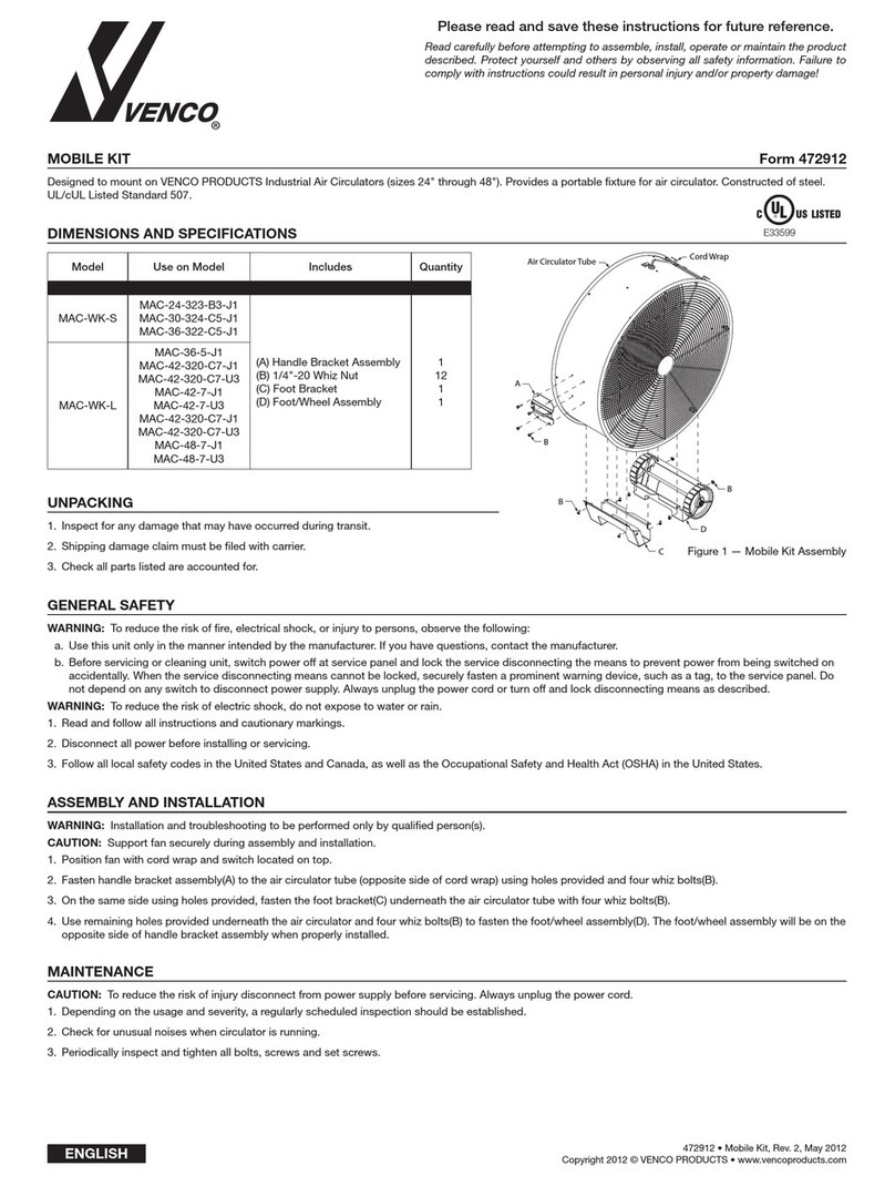
11.1 Annex-1: Electrical Wiring Diagrams
Motor connection without termic:
Motor connection with termic:
Table of contents
Other VENCO Fan manuals

VENCO
VENCO VBF-205 User manual

VENCO
VENCO MAC-CM-S User manual

VENCO
VENCO VAX-EX User manual

VENCO
VENCO VAX General instructions

VENCO
VENCO MAC-TC-24 User manual

VENCO
VENCO MAC-WK-S User manual

VENCO
VENCO VCFI User manual

VENCO
VENCO VCFI Series User manual

VENCO
VENCO MAC-18-339-B4-J1 User manual

VENCO
VENCO MAC-SM User manual
Popular Fan manuals by other brands

Mitsubishi Electric
Mitsubishi Electric LOSSNAY VL-220CZGV-EF Handbook

Suntec Wellness
Suntec Wellness Klimatronic CoolBreeze 3500 BV manual

Caframo
Caframo 747DC-WCS quick start guide

Trane
Trane RRU150F N Series Installation, operation and maintenance

HOMCOM
HOMCOM 824-050V90 Assembly & instruction manual

VOV
VOV VTS-1641 instruction manual