INSTALLATION MANUAL
INSTALLATION
8
Maximum Duct Lengths Recommended
to Achieve 80% Exhaust Efficiency
3¼” X10” HORIZONTAL
MAXIMUM DUCT LENGTH
3¼” X10” VERTICAL
MAXIMUM DUCT LENGTH
7” ROUND
MAXIMUM
DUCT LENGTH
ROOF OR
WALL CAP
WITH DAMPER
ELBOW(S)*
(90° AND/OR 45°)
91 ft. 79 ft. 92 ft. 1 0
82 ft. 71 ft. 78 ft. 1 1
73 ft. 62 ft. 62 ft. 1 2
* Standard elbows with 1” internal radius.
Contents
Before proceeding to the installation, check the contents of the box. If items are missing or
damaged, contact the manufacturer.
Make sure that the following items are included:
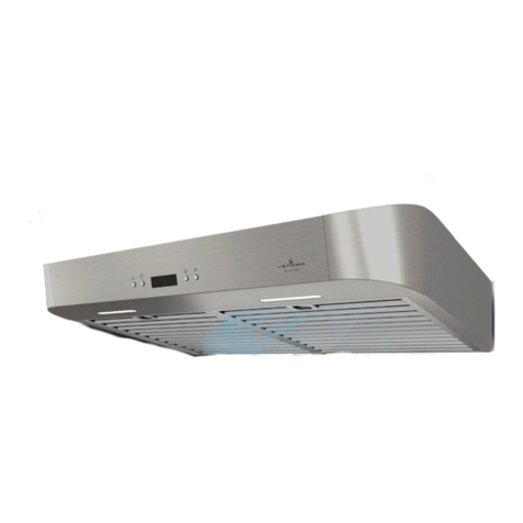
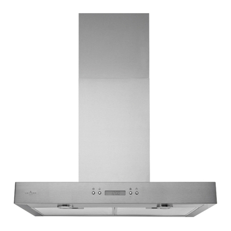
VCQDD1 Series VCQSEN1 Series
(2) GREASE FILTERS
(1) 3¼” X10” DAMPER ASSEMBLY
(FIND INSIDE OF HOOD)
(1) PARTS BAG** CONTAINING:
(6) NO. 8 X5/8”
RD. HD.
WOOD SCREWS
(2) INSTALLATION BRACKETS*
FOR FRAMED CABINET
(2) INSTALLATION BRACKETS*
FOR FRAMELESS CABINET
(1) TEMPLATE FOR DUCTING
(PRINTED BOTH SIDES)
(4) NO. 8-18 X1/2”
METAL SCREWS
(6) NO. 8 X1/2”
COUNTERSUNK
WOOD SCREWS
EZ1 COMPONENTS
C
L
AB
Apoyar esteborde contra la pared de atrásPlace this edge against back wall
=3¼” x 10”
=3¼” x 14”
RECTANGULARDUCTING7”ROUND DUCTING OR
Usethis template for marking; do not attempt to cut out the ducting hole through it.
NOTE:Thesecutouts are clearance holes; they do not need to be the exact size of ducting.
=3¼ po x 10 po
=3¼ po x 14 po
CONDUIT RECTANGULAIRECONDUIT RONDDE 7 PO OU
=3¼ pulg. x 10 pulg.
=3¼ pulg. x 14 pulg.
CONDUCTORECTANGULARCONDUCTOREDONDO
DE 7 PULG.O
Appuyer ce bord au mur arrière
Utiliserce gabarit pour marquer vos repères; ne pas tenter de découper
letrou pour le conduit à travers le gabarit.
NOTE: Les découpes incluent le jeu nécessaire à l’installation; elles ne doivent pas
être du format exact des conduits.
Useesta plantilla para crear marcados; no trate de cortar el
agujerodel conducto a través de la plantilla.
NOTA:Tobe translated in Spanish.
MARK WHERE INDICATED
FOR THE APPROPRIATESIZE DUCT OPENING
MARQUERLES REPÈRES AUX ENDROITS INDIQUÉS SELON
LE FORMATDE CONDUIT UTILISÉ
TITLE TOBE TRANSLATED IN SPANISH
Electricalaccess hole center
A=single blower hood
B=double blower hood
Centredu trou pour fil
d’alimentationélectrique
A=hotte ventilateur simple
B=hotte ventilateur double
Tobe translated in Spanish
Electricalaccess hole center
A=single blower hood
B=double blower hood
4¼”
10½”
14½”
8”
7½”
CC
CBendtemplate along graduated
scalewhen installing to framed
cabinet.
Pourune installation sous une
armoireà fond en retrait, utiliser les
lignespour mesurer l’épaisseur du
décalagecausé par le mur de
l’armoireet plier le gabarit en
conséquence.
Tobe translated in Spanish.
* FIND EZ1 BRACKETS ATTACHED INSIDE OF HOOD
** FIND PARTS BAG BEHIND THE DAMPER ASSEMBLY INSIDE OF HOOD
(1) 3¼” X10”
DAMPER ASSEMBLY*
(1) PARTS BAG*** CONTAINING:
(6) NO. 8 X5/8”
RD. HD.
WOOD SCREWS
* FIND INSIDE
OF HOOD
*** FIND PARTS BAG BEHIND THE DAMPER ASSEMBLY INSIDE OF HOOD
(2) INSTALLATION BRACKETS**
FOR FRAMED CABINET
(2) INSTALLATION BRACKETS**
FOR FRAMELESS CABINET
(1) TEMPLATE FOR DUCTING
(PRINTED BOTH SIDES)
(4) NO. 8-18 X1/2”
METAL SCREWS
(6) NO. 8 X1/2”
COUNTERSUNK
WOOD SCREWS
EZ1 COMPONENTS
C
L
AB
Apoyar esteborde contra la pared de atrásPlace this edge against back wall
=3¼” x 10”
=3¼” x 14”
RECTANGULARDUCTING7”ROUND DUCTING OR
Usethis template for marking; do not attempt to cut out the ducting hole through it.
NOTE:Thesecutouts are clearance holes; they do not need to be the exact size of ducting.
=3¼ po x 10 po
=3¼ po x 14 po
CONDUIT RECTANGULAIRECONDUIT RONDDE 7 PO OU
=3¼ pulg. x 10 pulg.
=3¼ pulg. x 14 pulg.
CONDUCTORECTANGULARCONDUCTOREDONDO
DE 7 PULG.O
Appuyer ce bord au mur arrière
Utiliserce gabarit pour marquer vos repères; ne pas tenter de découper
letrou pour le conduit à travers le gabarit.
NOTE: Les découpes incluent le jeu nécessaire à l’installation; elles ne doivent pas
être du format exact des conduits.
Useesta plantilla para crear marcados; no trate de cortar el
agujerodel conducto a través de la plantilla.
NOTA:Tobe translated in Spanish.
MARK WHERE INDICATED
FOR THE APPROPRIATESIZE DUCT OPENING
MARQUERLES REPÈRES AUX ENDROITS INDIQUÉS SELON
LE FORMATDE CONDUIT UTILISÉ
TITLE TOBE TRANSLATED IN SPANISH
Electricalaccess hole center
A=single blower hood
B=double blower hood
Centredu trou pour fil
d’alimentationélectrique
A=hotte ventilateur simple
B=hotte ventilateur double
Tobe translated in Spanish
Electricalaccess hole center
A=single blower hood
B=double blower hood
4¼”
10½”
14½”
8”
7½”
CC
CBendtemplate along graduated
scalewhen installing to framed
cabinet.
Pourune installation sous une
armoireà fond en retrait, utiliser les
lignespour mesurer l’épaisseur du
décalagecausé par le mur de
l’armoireet plier le gabarit en
conséquence.
Tobe translated in Spanish.
** FIND EZ1 BRACKETS ATTACHED INSIDE OF HOOD
(2) GREASE FILTERS
NOTE: 6" round ducting is possible but may reduce exhaust efficiency.

