Venture Lighting DRV195 User manual

LED Electronic Control Gear
DALI-2, Push-dim,0-10V, 10V PWM Constant Current Output
With 14-42VDC Output Series
GENERAL GUIDELINES
Venture Lighting Europe Ltd. 1st Floor, Building 2, Croxley Business Park, Watford, Hertfordshire, WD18 8YA
1
General Guidelines 1
Parameters 3
Diagram and Installation Manual 5
PUSH Dimming 5
DALI Dimming 6
0-10V or 10V PWM Dimming 7
DIP Switch Table 8
Parallel Wiring 9
Wiring Type and Cross Section 9
Release of the Wiring 10
Fixing Conditions 10
Wiring Guidelines 10
Mechanical 11
ENEC approved compact LED driver with DALI, 0-10V,
PWM and Push-dimming.
Constant current output 250-600mA (DRV196) or
650-1100mA (DRV195). Voltage range 14-42V.
DRV195 and DRV196 Driver Specification

Product description
Housing Properties
Typical applications
Venture Lighting Europe Ltd. 1st Floor, Building 2, Croxley Business Park, Watford, Hertfordshire, WD18 8YA
2
LED Electronic Control Gear
DALI-2, Push-dim,0-10V, 10V PWM Constant Current Output
With 14-42VDC Output Series
- DALI 2, Push-Dim, 0-10V, PWM
- ENEC, CE, CB approved
- Adjustable constant current operation from 250mA to 110mA across the range
- Class II
- SELV
- Accepts 0.5-1.5mm2 mains cable
- Independent ECG with strain-relief
- Ambient range -25C - +45C
- 50,000Hrs nominal life
- 5-year guarantee
- Flicker depth <3%
- Active PFC
- Permanent EEPROM memory for DALI and Push-Dim
- Polycarbonate casing, white
- IP20
- Ceiling panel and downlight
- Office, commercial, hospitality

PARAMETERS
MODEL
OUTPUT
DC voltage range
(14-42V) @36V
Rated current
650-1100mA(selectable every 50mA, preselected 650mA) 250-600mA(selectable every 50mA, preselected 250mA)
Current tolerance
±5%
Max. output power
39.6
Dimming range
DALI 1%-100%; Push-DIM 2%-100%, 0-10V: 10%-100%
Ripple &noise(max.)
<1V
Starting time
<0.3S @230V
Warm up time to 60%
<1.0 @230V
Turn off time
<2.0 @230V
Flicker percentage
<3%
Flicker index
<1%
INPUT
AC Voltage range
200-240VAC
Frequency range
47 ~ 63Hz
Max. input power
45.8
Power factor(typ.)
>0.95 at full power
>0.95 at full power
THD
<7%
Efficiency (typ.)
87%
85%
AC current (typ.)
126-205
In-rush current (typ.)
<40A/350uS@230V
Max. No. of psus on 16A
circuit breaker
Leakage current
0.5mA
Switching cycles
>15,000
Standby power
<1W
Venture Lighting Europe Ltd. 1st Floor, Building 2, Croxley Business Park, Watford, Hertfordshire, WD18 8YA
3
LED Electronic Control Gear
DALI-2, Push-dim,0-10V, 10V PWM Constant Current Output
With 14-42VDC Output Series
DRV195 DRV196

Protection
Over current
√√
Short circuit
√
√
Over voltage
√√
Over temperature
√
√
No-load operation
√√
No damage at wrong mains
voltage level √√
Environment
Working Temp.
-20°C ~45°C
Max. case(tc point) Temp.
85°C
Working humidity
20%-85%RH
Storage temp., humidity
-40°C ~80°C
Connection
AC Connector
Push Type Terminal, Max. 1.5mm2 input cable cord
DC Connector/
Not included
Output wire(type, length)
Not included
Others
MTBF
Warranty years
5
Lifespan (hrs) @ ta=25°C
50000H
DALI Standard
IEC 62386-101: 2014, IEC 62386-102: 2014, IEC 62386-207: 2009, DALI-2
Glow wire test
850°C for 5S; 650°C for 30S
Dimension L x W x H
125X76X30mm
Packing
50pcs per cartons, Size 57.5x18.5x19cm, Gross Weight kgs
Note
DALI and PUSH with memory function
Venture Lighting Europe Ltd. 1st Floor, Building 2, Croxley Business Park, Watford, Hertfordshire, WD18 8YA
4
LED Electronic Control Gear
DALI-2, Push-dim,0-10V, 10V PWM Constant Current Output
With 14-42VDC Output Series

DIAGRAM&INSTALLATION MANUAL
PUSH Dimming
PUSH-DIM, also known as Switch-Dim or Touch-Dim. To be able to make simple light management systems,
the one4all also integrated PUSH-DIM Function. This makes it possible to dim and switch them directly with
mains AC voltage using the PUSHI control terminals (PUSH-DIM interface). Only one commercial push-button
is required; the controller takes over the drivers. PUSH-DIM may never be used at the same time as a DALI
control system.
Circuit diagram
Wiring and cable compensation
a) Do not use more than 20 one4all ECGs in a single PUSH-DIM application (up to 20 ECGs can be
controlled by one push-button). The greater the number of one4all ECGs controlled imultaneously, the
greater the risk of asynchronisms.
b) The cable length between the push-button and the farthest one4all ECGs may not be longer than 105
meters. Compensation measures must be applied for line lengths required to be more than 25 meters long
(bell transformer, resistance).
c) The push button can only be connected to the AC/L and PUSH terminals of the driver. It results in the short
circuit if the Push Button is connected to the AC/N terminal.
Instructions
Note:
a) Factory defaults 100% brightness, dimming level down to 2%.
b) Built--in with permanent memory:
Operation
Action duration
Action
Ultra Short Press
<0.04 sec
Won’t cause any action
Briefly Press
0.04-0.5 sec
Light ON/OFF
Press and hold
at ON status 0.50-5.0sec
Brightness Dimming down to 2%, or up to
100%
Press and hold
at OFF status 0.50-5.0sec Brightness Dimming From 2% up to 100%
Long Press >5.0 sec Won’t cause any action
C350-421100DBF
LED+
LED-
DIM-
DIM+
DA2
DA1
PUSH
AC-N
AC-L
N
L
AC200-240V
50/60Hz
PUSH
Button
PRI SEC
Venture Lighting Europe Ltd. 1st Floor, Building 2, Croxley Business Park, Watford, Hertfordshire, WD18 8YA
5
LED Electronic Control Gear
DALI-2, Push-dim,0-10V, 10V PWM Constant Current Output
With 14-42VDC Output Series

Light returns to the previous dimming level when switched off and on again, even at power failure.
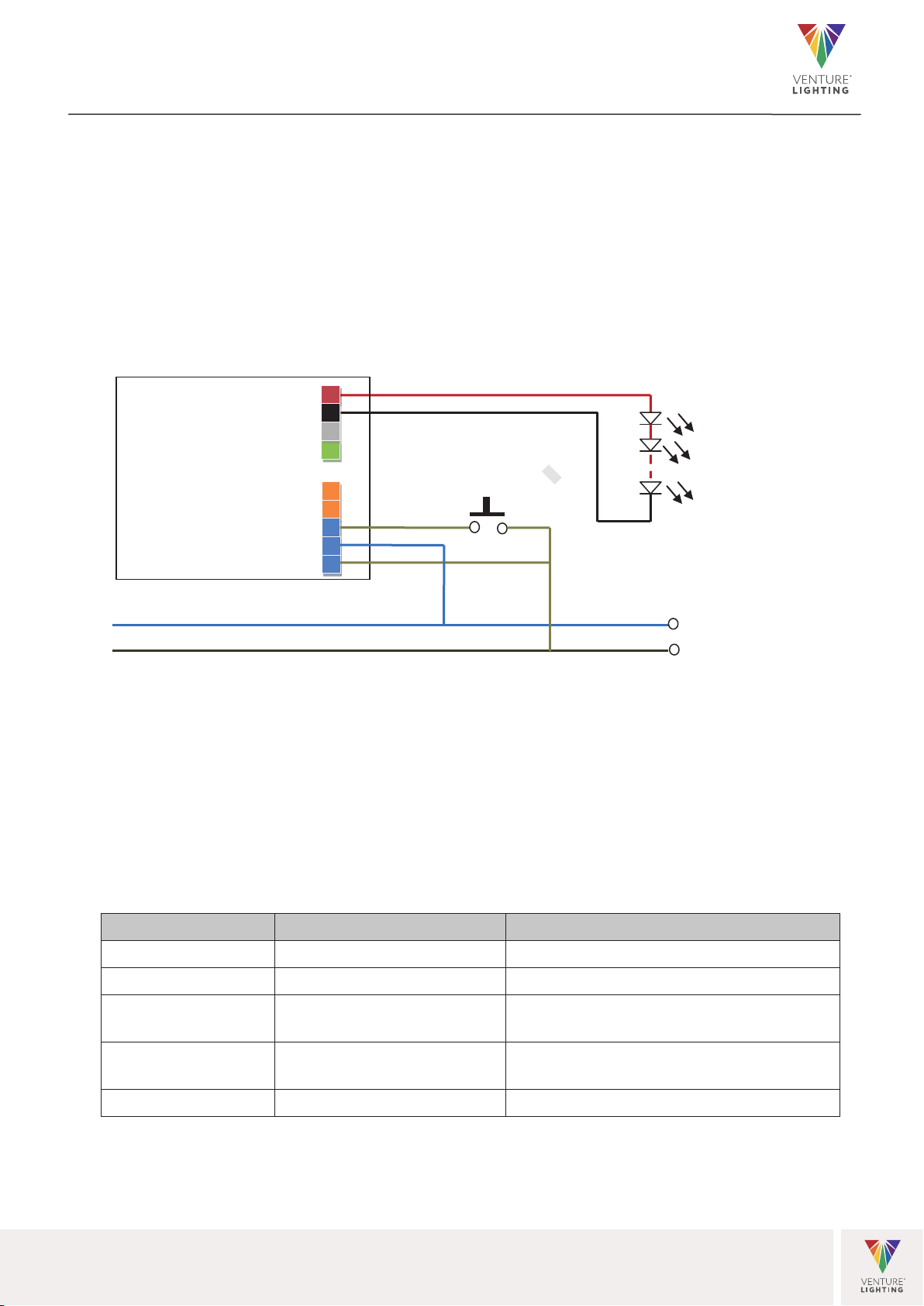
c) Synchronization of switching state and dimming direction:
For physical reasons, a PUSH-DIM system can work asynchronously; in other words, the switching state
and dimming direction of the individual luminaires are different. The following steps are used to
synchronize a PUSH-DIM system:
1. Step: Press and hold (> 0,5 s) All luminaires switch on
2. Step: Press briey (< 0,5 s) All luminaires switch o
3. Step: Press and hold (> 0,5 s) All luminaires switch on and dim
d) The PUSH-DIM wiring and the operator button must be rated for mains voltage (240 V).
e) It must be AC voltage with a frequency between 48 and 63 Hz.
f) Warning: Make sure the conduct core connected to PUSH terminal is not exposed, as it connected to the
live wire.
Asynchronism
As a matter of principle, asynchronisms can occur with push-button operation in systems with more than one
ECGs. The higher the number of ECGs and the longer the control line length, the greater the chance of
asynchronisms. In order to avoid lighting installations running asynchronously in practice, the permissible
number of ECGs(20) and the total line length of 25 meters must be adhered to.
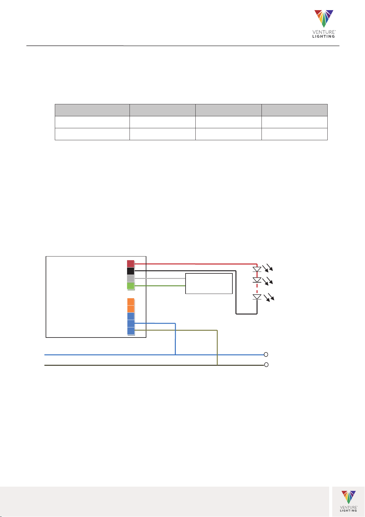
DALI Dimming
Circuit diagram
Instructions
a) Compatible with both DALI-2 application controller or DALI-I master.
b) Connect the DALI signal to the DA1 and DA2 terminals (polarity-free)
c) Addressing possible:
•Individually (max. 64 IP addresses)
•In groups (max. 16)
•All together
d) The least dimming depth of DALI is of 1% * Iout.
e) Built--in with permanent memory: light returns to the previous dimming level when switched off and on
Venture Lighting Europe Ltd. 1st Floor, Building 2, Croxley Business Park, Watford, Hertfordshire, WD18 8YA
6
LED Electronic Control Gear
DALI-2, Push-dim,0-10V, 10V PWM Constant Current Output
With 14-42VDC Output Series

again, even at power failure.
f) Wiring in groups not necessary
g) Signal voltage requirement.
If the ECGs are not reacting to the command of the control unit. Please inspect the wiring; approx. 16 V
DC must be applied to the DALI terminal of the ECG.
DALI INPUT
MIN
TYP
MAX
High level
9.5V
16V
22.5V
Low level
-6.5V
0
6.5V
0-10V or 10V PWM Dimming
Circuit diagram
Instructions
a) Compatible with both passive and active 0-10V dimmer
For active dimmer, over 11.0VDC output to ECG is not permitted.
b) Connect the 0-10V Master or 10V PWM Master following the above diagram, then you can dim with the
dimmer.
c) Please note: There has” +”& ”-“pole for 0-10V and 10V PWM, don’t connect the wrong way, otherwise,
it cannot dim the light.
d) The maximum permissible length of the control line is 100 meters.
e) No memory function.
C350-421100DBF
LED+
LED-
DIM-
DIM+
DA2
DA1
PUSH
AC-N
AC-L
N
L
AC200-240V
50/60Hz
0-10V/10V PWM
Dimmer
PRI SEC
Venture Lighting Europe Ltd. 1st Floor, Building 2, Croxley Business Park, Watford, Hertfordshire, WD18 8YA
7
LED Electronic Control Gear
DALI-2, Push-dim,0-10V, 10V PWM Constant Current Output
With 14-42VDC Output Series
DRV195
0-10V dimming terminals source 0.1mA current and can be used with passive or active electronics. However,
It is not recommended to connect more than one ECG to a passive electronic network.
Minimum dimming level when using 0-10V input is 5.7% of current range.

DIP S.W.
Iout 1 2 3 4 5
650mA
-
-
-
-
-
700mA
ON
-
-
-
-
750mA
ON
-
-
800mA
-
-
ON
-
-
850mA
ON
-
ON
-
-
900mA
-
ON
ON
-
-
950mA
-
-
ON
ON
-
1000mA
ON
-
ON
ON
-
1050mA
- ON ON ON -
1100mA
ON ON ON ON -
DIP S.W.
Iout 1 2 3 4 5
250mA
-
-
-
-
-
300mA
ON
-
-
-
-
350mA
-
ON
-
-
400mA
ON
ON
-
-
-
450mA
-
-
ON
-
-
500mA
ON
-
ON
-
-
550mA
-
ON
ON
-
-
600mA
ON
ON
ON
-
-
Venture Lighting Europe Ltd. 1st Floor, Building 2, Croxley Business Park, Watford, Hertfordshire, WD18 8YA
8
LED Electronic Control Gear
DALI-2, Push-dim,0-10V, 10V PWM Constant Current Output
With 14-42VDC Output Series
DRV195 DRV196
DIP Switch Tables
Drivers are settable by onboard DIP switches found inside the cable cover. Take note that permitted voltage range
is 14-42V regardless of current setting and therefore maximum power is reduced at lower currents.

Parallel wiring
DALI
AC-N
AC-L
D
0-10V or 10V PWM
0
Wiring type and cross section
The wiring can be in stranded wires with ferrules or solid with a cross section of 0.5–1.5 mm². Strip
DA2
DA1
AC-N
PUSH
AC-L
DALI
Master
DA2
DA1
AC-N
PUSH
AC-L
LED+
LED-
DIM+
DIM-
0-10V Master/
10V PWM Master
LED+
LED-
DIM+
DIM-
C350-421100DBF #1
C350-421100DBF #2
C350-421100DBF #1
C350-421100DBF #2
Venture Lighting Europe Ltd. 1st Floor, Building 2, Croxley Business Park, Watford, Hertfordshire, WD18 8YA
9
LED Electronic Control Gear
DALI-2, Push-dim,0-10V, 10V PWM Constant Current Output
With 14-42VDC Output Series

8-10mm of insulation from the cables to ensure perfect operation of the push-wire terminals. Use one wire
for each terminal connector only
Release of the wiring
Press down the “push button” and remove the cable from front.
Fixing conditions
Dry, acid-free, oil-free, fat-free. It is not allowed to exceed the maximum ambient temperature (ta) stated
on the device. Minimum distances stated below are recommendations and depend on the actual luminaire.
Is not suitable for fixing in corner.
Wiring guidelines
•All connections must be kept as short as possible to ensure good EMI behavior.
•Mains leads should be kept apart from LED Driver and other leads (ideally 10 –20 cm distance)
•Secondary switching is not permitted
•Incorrect wiring can damage LED modules
•The wiring must be protected against short circuits to earth (sharp edged metal parts, metal cable
clips, louver, etc.)
8 –10 mm
LED Module
Venture Lighting Europe Ltd. 1st Floor, Building 2, Croxley Business Park, Watford, Hertfordshire, WD18 8YA
10
LED Electronic Control Gear
DALI-2, Push-dim,0-10V, 10V PWM Constant Current Output
With 14-42VDC Output Series

MECHANICAL
PACKAGING
Master
C arton
Qty per carton 50
Length x Width x Height (cm) 40x40x15
Net Weight (kg) 9.5
G ross Weight (kg) NA
Venture Lighting Europe Ltd. 1st Floor, Building 2, Croxley Business Park, Watford, Hertfordshire, WD18 8YA
11
LED Electronic Control Gear
DALI-2, Push-dim,0-10V, 10V PWM Constant Current Output
With 14-42VDC Output Series
This manual suits for next models
1
Table of contents
Other Venture Lighting Floodlight manuals
Popular Floodlight manuals by other brands

WE-EF
WE-EF FLC210 Installation and maintenance instructions

XanLite
XanLite XP TECHNIC LINE PR20WMDS user manual

Chauvet
Chauvet Colorado 1-Quad Tour user manual

VONROC
VONROC WL507AC Original instructions

Eye Lighting
Eye Lighting H566 Series Installation & maintenance

EuroLite
EuroLite LED D-4000 user manual