Venture Products Ventrac KP540 User manual

Revised 02/05/20
09.10022
POWER RAKE
KP540
OWNER/OPERATOR’S
MANUAL & PARTS LIST

ii
TO THE OWNER
Venture Products Inc. reserves the right to make changes
in design or specifications without obligation to make like
changes on previously manufactured products.
Orrville, OH
www.ventrac.com
Model # (A): _______________________
Serial # (B): ________________________
Affix Part/Serial Number label here
Product Identification
If you need to contact an Authorized Ventrac Dealer for information on servicing your product,
always provide the Product Model and Serial numbers.
Please fill in the following information for future reference. See picture below to find the loca-
tion of the identification number. Record them in the spaces provided below.
Date of Purchase: Month _________________ Day ___________ Year ___________________
Dealer: _______________________________________________________________________
Dealer Address: ________________________________________________________________
________________________________________________________________
Dealer Phone Number: __________________________________________________________
Dealer FAX Number: ____________________________________________________________

TABLE OF CONTENTS
iii
INTRODUCTION SECTION A
Description & Specifications ................................A-1
SAFETY SECTION B
Safety Symbols .......................................B-1
Decals ...........................................B-2
General Safety Procedures.................................B-3
Safety Operation & Techniques...............................B-4
OPERATION SECTION C
Attaching ..........................................C-1
Detaching..........................................C-1
Operating ..........................................C-1
MAINTENANCE/ADJUSTMENTS SECTION D
Bearing Lubrication .....................................D-1
Hydraulic Fluid Level ....................................D-1
Carbide Tip Replacement .................................D-1
PARTS & ILLUSTRATED DRAWINGS SECTION E
Main Frame, Hitch Frame, & Filter ...........................E-1 & 2
Pump, Valve, & Adjustment Handle ..........................E-3 & 4
Rotor, Rotor Frame, & Motor ..............................E-5 & 6
Height Adjuster .....................................E-7 & 8
Wheel Frame & Shields ................................E-9 & 10
Side Wings, Dirt Flap, & Power Angle ........................E-11 & 12
WARRANTY

A-1
INTRODUCTION
Product Description
KP540 Power Rake
The Ventrac KP540 power rake is an excellent attachment that allows for quick preparation of a new
seed bed.
Seventy-two replaceable, carbide tipped teeth aggressively refine the soil and move stones and
debris forward, or to either side using the power angle feature. By shifting a lever, the rotor can be
reversed to allow the operator to pull material away from buildings and other obstacles.
Single rotating crank adjustment moves teeth up or down, from scratching the surface to a three-inch
depth in increments of 1/8 inch.
Stationary gauge wheels keep the rake centered with the tractor.
Adjustable side wings can be used to keep stones and debris in the work path.
Ventrac KP540 Specifications
Overall Height ....................................38 inches
Overall Length ....................................62 inches
Overall Width.....................................61 inches
Rotor Width .....................................54 inches
Cutting Depth Below Ground Level ..........................3 inches
Weight .......................................520 pounds
Hydraulic Fluid Capacity .............................4-1/2 gallons
Venture Products, Inc. reserves the right to change these specifications without notice.

SAFETY
B-1
ATTENTION:
This symbol identifies potential health and
safety hazards. It marks safety precautions.
Your safety and the safety of others is involved.
SIGNAL WORD DEFINITIONS
Indicates a potentially hazardous situation
which, if not avoided, may result in minor
or moderate injury and/or property dam-
age. It may also be used to alert against
unsafe practices.
Indicates a potentially hazardous situation
which, if not avoided, could result in death
or serious injury.
Indicates an imminently hazardous situa-
tion which, if not avoided, will result in
death or serious injury. This signal word is
limited to the most extreme cases.

B-2
The following decals must be maintained on your Ventrac Power Rake. If any decals
are faded or missing, contact your dealer promptly for replacements.
SAFETY
A
C
Decal Page &
Location Description Part Number
AE-9, #26 Danger - Pinching Hazard 00.0102
BE-9, #28 High Pressure Fluid Hazard 00.0103
CE-1, #16 Warning - Read Owner's Manual 00.0217
B

B-3
SAFETY
General Safety Procedures
for Ventrac Tractors, Attachments, & Accessories
Read and understand the operator’s manual before operating this equipment.
Observe and follow all safety decals.
DO NOT let children or any untrained person operate the tractor or attachment. Make sure that all
operators of this equipment are thoroughly trained in using it safely.
Never allow additional riders on the tractor or attachments.
DO NOT operate tractor or attachments if you are under the influence of alcohol, drugs, or medication
that may impair judgment or cause drowsiness, or if you are not feeling well.
Operate all controls from the operator’s seat only.
Before operating equipment, make sure all shields are in place and fastened.
Ensure the attachment or accessory is locked or fastened securely to the tractor before
operating. See tractor manual for locking procedure.
Ensure that all bystanders are clear of the tractor and attachment before operating. Be especially
careful and observant if other people are present. Never assume that bystanders will remain where
you last saw them.
Always look in the direction the tractor is moving.
Never direct the discharge of any attachment in the direction of people, animals, buildings, vehicles,
or objects of value.
Stop operation immediately at any sign of equipment failure and correct the problem before
continuing to operate. An unusual noise can be a warning of equipment failure or a sign that
maintenance is required.
Before adjusting, cleaning, lubricating, or changing parts on the tractor or attachment, engage the
parking brake, lower the attachment to the ground, stop the engine, and remove the ignition key.
To prevent the risk of uncontrolled equipment movement on tractors equipped with 2 speed axles,
always shift the transaxle range with the tractor stationary on level ground and with the parking brake
engaged.
If equipment is to be left unattended, engage the parking brake, lower the attachment to the ground,
stop the engine, and remove the ignition key.

SAFETY
B-4
KP540 Safety Procedures
Before making any repairs or adjustments, lower
attachment to the ground, set parking brake, shut
the engine off, and remove the key.
Read and understand the operator’s manual before
operating this equipment.
Always use eye protection when working with
carbide tips.
Venture Products Inc. recommends ALWAYS
wearing eye and ear protection when operating the
power rake.

Attaching
1. Adjust the height of the rotor assembly until the indicator is located in the attaching zone^.
2. Drive the tractor slowly forward into the hitch arms on the power rake. Align the lift arms of the
tractor with the power rake hitch arms by raising or lowering the front hitch and complete the en-
gagement.
3. Once completely engaged, close the front hitch locking lever.*
4. Engage the parking brake* and shut off engine.
5. Place the attachment belt over the outside groove of the PTO drive pulley on the tractor. Ensure
the belt is properly seated in each pulley.
6. Engage the PTO spring tension lever.*
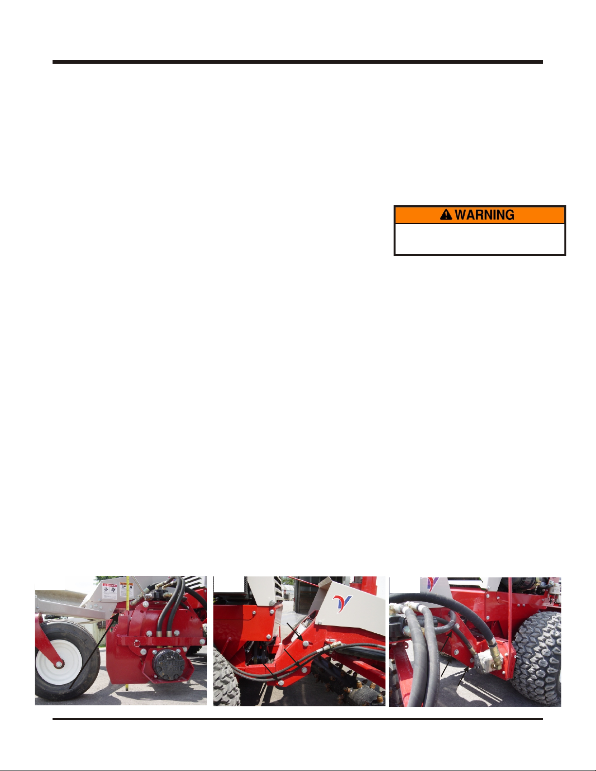
7. Wipe the quick couplers clean, and connect to the tractor. If equipped, connect the hoses and quick
couplers so the red indicators are paired together and the yellow indicators are paired together.
Detaching
1. Adjust the height of the rotor assembly until the indicator is located in the attaching zone^.
2. Park the tractor on a level surface and set the parking brake.*
3. Lower the power rake to the ground.
4. Shut off tractor engine.
5. Disengage the PTO spring tension lever.*
6. Remove the attachment belt from the PTO drive pulley of the tractor.
7. Disconnect the hydraulic quick couplers from the tractor.
8. Disengage the hitch locking lever.*
9. Restart tractor and slowly back away from the power rake.
*Refer to tractor manual for operation of controls.
^ Attaching zone is set for the standard lift arm height of Ventrac 4000 series tractors. Variables
such as tire size, tire inflation, and attempting to attach on an uneven surface will affect the proper
location of the attaching zone. The purpose of the attaching zone is to remove all the attachment
weight from the tractor hitch before removing from the tractor. This is done by lowering the rotor to
the ground and allowing it to carry the weight of the power rake. This will ensure a quick and easy
hitch alignment when reattaching to the tractor.
Operating Techniques & Tips:
Using low range on the tractor during operation of the power rake is recommended in most conditions.
Operator must be sitting on the tractor seat before the PTO can be engaged. The recommended
tractor engine speed during operation is 2,800-3,600 RPM. Adjust the engine RPM and tractor ground
speed to get the desired finish.
Before raking, clear the area of large rocks, wood, and leftover construction materials.
The rake can be used to “rough in” the area prior to finishing. This is done by setting the rake depth
and pushing dirt into low areas and up to buildings, trees, and other obstructions.
The rotor reverse feature allows you to pull material away from buildings, trees, and obstructions,
eliminating most hand raking.
If the rotor becomes plugged with sticks and debris, or becomes wrapped with string or wire, reversing
the rotor will make quick work of cleaning it out.
OPERATION
C-1

Bearing Lubrication
Grease the rotor bearing every 25 hours. Do not over grease. One pump is sufficient.
Hydraulic Fluid Level
Check hydraulic fluid level every 20 hours. Add Ventrac Hydro•Torq XL hydraulic oil, if necessary.
Carbide Tip Replacement
The carbide tips may eventually need to be replaced.
1. Remove the carbide tips using a cold chisel and a hammer. Place the cold chisel against the bot-
tom flange of the tip in the slot of the protective sleeve and hammer the tip out.
2. Lightly grease the retainer ring and the base of the new tip.
3. Using a channel lock pliers, compress the retainer ring on the tip.
4. Insert the tip into the rotor sleeve and tap in with a hammer.
MAINTENANCE
D-1
Always use eye protection
when working with carbide tips.
KP540 Power Rake Hitch Arm Leveling
Variables such as tire size, tire inflation, power unit hitch height, or hitch arm replacement may require one to level the main
frame of the power rake.
Follow all safety precautions when doing any maintenance or adjustments.
1. With the Power Rake attached to the power unit, position entire unit on a level surface.
2. Raise the rotor assembly so as to clear the floor by a half inch.
3. Place the power units’ hydraulic front lift lever in the float position.
4. Angle the rotor assembly all the way to the left.
5. Measure from a location on the rotor assembly frame down to the level surface. See photo.
6. Angle the rotor assembly all the way to the right.
7. Again measure from the same side and location on the rotor assembly frame down to the level surface.
8. If the two measurements are not with-in 1/8–1/4* of an inch, the main frame should be leveled.
9. Loosen the six bolts that secure the hitch frame to the main frame.
10. Raise or lower the power units’ hitch arms to change the angle between the hitch arm frame and the main frame.
11. Repeat steps 4 –7 until the measurements are the with-in 1/8–1/4* of an inch.
12. Tighten the six bolts that secure the hitch frame to the main frame.
* 1/8-1/4 of an inch is generally preferred for most applications. Other applications may require a finer adjustment.
Note: The above procedure may be used to adjust the rake to an intentional rotor angle.
Fig 1 Fig 2 Fig 3
Measure point

PARTS
MANUAL
KP540

PARTS
E-1
ILLUSTRATED DRAWING
MAIN FRAME, HITCH FRAME, & FILTER

MAIN FRAME, HITCH FRAME, & FILTER
E-2
PARTS
REF. PART NO. DESCRIPTION QTY.
1......62.0939 .............FRAME, HITCH ASSEMBLY KP540 ......................1
2......92.08 ..............NUT, 1/2-13 USS ................................6
3......96.08 ..............WASHER, LOCK 1/2 ..............................6
4......95.08 ..............WASHER, FLAT 1/2 SAE ...........................12
5......25.2501-10-12 .........FITTING, 90 ME 5/8 X 3/4 ...........................1
6......22.0030 .............HOSE, ASM X 6" 5/8 PUSHLOCK .......................1
7......25.2404-10-12 .........FITTING, M CONN 5/8 X 3/4 ..........................2
8......21.0078 .............FILTER, HYDRAULIC 10 MICRON ......................1
9......21.0057 .............FILTER, HEAD 3/4" NPT PORTS ........................1
10......22.0031 .............HOSE, ASM X 16" 5/8 PUSHLOCK .......................1
11 ......99.SF0404-1 ..........BOLT, SF 1/4-20 X 1/2 W/RUBBER .......................2
12......64.1009 .............MOUNT, OIL FILTER KP ............................1
13......99.SF05 ............NUT, SF 5/16-18 USS ..............................3
14......90.0810 .............BOLT, 1/2-13 USS X 1 1/4............................4
15......90.0814 .............BOLT, 1/2-13 USS X 1 3/4............................2
16......00.0217 .............DECAL, WARNING READ OWNERS MAN. ..................1
17......62.0937 .............FRAME, MAIN KP540 .............................1
18......95.05 ..............WASHER, FLAT 5/16 SAE ...........................3
19......90.0506 .............BOLT, 5/16-18 USS X 3/4 ............................3
20......22.0032 .............HOSE, ASM X 30" 1 PUSHLOCK ........................1
21......25.2501-12-12 .........FITTING, 90 ME 3/4 X 3/4 ...........................1
22......23.0127-1............DIP STICK, ASM 5-3/4" KP (SERIAL # 1001-1026) ..............1
23......23.0134 .............DIP STICK, ASM 5-3/4" KP (SERIAL # 1027 - ) ................1
24......29.BF06MP0245 ........FITTING B. 3/8 BARB 1/8 NPT 45 .......................2
25......11.0032 .............CLAMP, HOSE S/S 7/16-25/32.............................4
26 ......27.P06-6IN ............HOSE, PUSHLOCK X 3/8 x 6" .........................2
27......29.BF06MP04 .........FITTING B. 3/8 BARB 1/4 NPT .........................2
28......25.3700-4-4-4..........FITTING, F TEE 1/4 X 1/4 X 1/4.........................1
29......64.1076 .............BRACKET, BREATHER TUBE MOUNT ....................1
30......29.0093 .............PIPE, BREATHER PLUG 1/4 ..........................1
31......00.0100 .............DECAL, MADE IN USA ............................1

PARTS
E-3
ILLUSTRATED DRAWING
PUMP, VALVE, & ADJUSTMENT HANDLE

PUMP, VALVE, & ADJUSTMENT HANDLE
E-4
PARTS
REF. PART NO. DESCRIPTION QTY.
1......83.H12 .............BUSHING, 3/4" H ...............................1
2......83.BK60H............PULLEY, 6" H-BUSH .............................1
3......81.B048.............BELT, B48 ...................................1
4......90.0608 .............BOLT, 3/8-16 USS X 1 .............................2
5......99.E0004 ............NUT, WING 1/4-20 USS ............................1
6......60.0721 .............SHIELD, DRIVE PULLEY ...........................1
7......90.0506 .............BOLT, 5/16-18 USS X 3/4 ...........................2
8......99.SF05 ............NUT, SF 5/16-18 USS .............................2
9......64.1012 .............SUPPORT, SHIFT ROD KP ..........................1
10......05.0045 .............GROMMET, 3/4ID,1 3/8OD,1/2THK ......................1
11 ......47.0001 .............KNOB, SM. #80 3/8-16 THREAD .......................1
12......42.0452 .............ROD, SHIFT KP ................................1
13......02.HP0313 ...........HAIRPIN, 3/32 X 1-5/8.............................1
14......22.0032 .............HOSE, ASM X 30" 1 PUSHLOCK .......................1
15......25.6801-12-12 .........FITTING, 90 ME 3/4 X 3/4 ...........................1
16......99.SF06 ............NUT, SF 3/8-16 USS..............................2
17......85.K0310 ............KEY, 3/16 X 1 1/4 ...............................1
18......25.6801-08-10 .........FITTING, 90 ME 1/2 X 5/8 ...........................1
19......21.0103 .............PUMP, BARNES CW 16 CCR .........................1
20......20.0186 .............HOSE, ASM X 19" 1/2-2W #8 .........................1
21......22.0031 .............HOSE, ASM X 16" 5/8 PUSHLOCK ......................1
22......25.2501-10-12 .........FITTING, 90 ME 5/8 X 3/4 ...........................1
23......20.0182 .............HOSE, ASM X 27" 1/2-2W #8-3500 ......................2
24......25.2501-08-08 .........FITTING, 90 ME 1/2 X 1/2 ...........................2
25......03.0408 .............CLEVIS PIN, 1/4 X 1..............................1
26......02.CP0304 ...........COTTER PIN, 3/32 X 1/2 ...........................1
27......23.0121-4............HANDLE, DRILLED ..............................1
28......81.0024 .............LINK, CONNECTOR #60 ...........................1
29......25.2501-08-12 .........FITTING, 90 ME 1/2 3/4 ............................1
30......23.0121-1............VALVE, 23.0121 W/OUT HANDLE ......................1
.......23.0121-2............BRACKET, CONTROL LEVER ENERGY ...................1
31......95.06 ..............WASHER, FLAT 3/8 SAE ...........................4
32......96.06 ..............WASHER, LOCK 3/8 .............................4
33......90.0606 .............BOLT, 3/8-16 USS X 3/4 ............................4
34......85.SS22 ............Set Screw, 1/2-20 X 1/4"............................1

PARTS
E-5
ILLUSTRATED DRAWING
ROTOR, ROTOR FRAME, & MOTOR

ROTOR, ROTOR FRAME, & MOTOR
E-6
PARTS
REF. PART NO. DESCRIPTION QTY.
1......99.A08 .............LOCKNUT, STOVER 1/2-13 USS .......................4
2......60.0841 .............GUARD, MOTOR KP .............................1
3......20.0182 .............HOSE, ASM X 27" 1/2-2W #8-3500 ......................2
4......25.6400-08-10 .........FITTING, M CONN 1/2 X 5/8 .........................2
5......21.0102 .............MOTOR, WHEEL, WHITE 261CCR (SERIAL # 1001-1089) .........1
5......21.0114 .............MOTOR, WHEEL PEERLESS 250CC (SERIAL # 1090-1159) ........1
5......21.0120 .............MOTOR, WHEEL PEERLESS 250CC (SERIAL # 1160-) ...........1
6......85.K0510 ............KEY, 5/16 X 1 1/4 ...............................1
7......62.0942 .............MOUNT, MOTOR KP .............................1
8......90.0808 .............BOLT, 1/2-13 USS X 1 .............................6
9......95.08 ..............WASHER, FLAT 1/2 SAE ...........................8
10......90.0820 .............BOLT, 1/2-13 USS X 2 1/2 (SERIAL # 1001-1089) ..............4
10......90.0822 .............BOLT, 1/2-13 USS X 2 3/4 (SERIAL # 1090-) .................4
11 ......50.0167 .............HUB, DRIVE KP540 1"SHAFT (SERIAL # 1001-1086) ...........1
11 ......50.0176 .............HUB, DRIVE KP540 1"SHAFT (SERIAL # 1087-) ..............1
12......91.0808 .............BOLT, 1/2-20 SAE X 1 .............................6
13......96.08 ..............WASHER, LOCK 1/2 .............................6
14......80.0324 .............ROTOR, ASSEMBLY KP540 .........................1
15......79.0052 .............TOOL, CARBIDE.545 STEM X1-9/16 ....................72
16......79.0052-1............SLEEVE, PROTECTIVE 7/8X1X3/4 .....................72
17......95.20 ..............WASHER, FLAT 1 1/4 SAE ..........................3
18......64.1014 .............COVER, BEARING DIRT KP .........................1
19......55.PB25020-1 .........BEARING, PILLOW BLOCK 1 1/4 .......................1
20......93.20 ..............NUT, 1 1/4-12 SAE ..............................1
21......29.GF0001 ...........GREASE FTG, 1/4 SAE ST ..........................1
22......64.1005 .............MOUNT, BEARING KP ............................1
23......90.0814 .............BOLT, 1/2-13 USS X 1 3/4 ...........................2
24......99.SF08 ............NUT, SF 1/2-13 USS..............................6
25......62.0938 .............FRAME, ROTOR KP540............................1
26......95.16 ..............WASHER, FLAT 1 SAE ............................1
27......99.E0069 ............NUT, CASTLE 1"-20 UNEF ..........................1
28......02.CP0516 ...........COTTER PIN, 5/32 X 2 ............................1
29......99.B0078 ............WASHER, MACH 1 1/4 14 GA ........................2
30......64.1243 .............PLATE, SPACER HYD WHEEL MOTOR (SERIAL # 1090-) .........1
31......89.0086 .............KIT, SEAL FOR 21.0114 MOTOR (SERIAL # 1090-1159) ...........1
31......89.0087 .............KIT, SEAL FOR 21.0120 MOTOR (SERIAL # 1160-) .............1

PARTS
E-7
ILLUSTRATED DRAWING
HEIGHT ADJUSTER

HEIGHT ADJUSTER
E-8
PARTS
REF. PART NO. DESCRIPTION QTY.
1......90.0628 .............BOLT, 3/8-16 USS X 3 1/2 ...........................1
2......47.0216 .............KNOB, HEIGHT ADJUSTER HANDLE ....................1
3......99.SF06 ............NUT, SF 3/8-16 USS..............................6
4......42.0451 .............CRANK, ADJUSTING KP ...........................1
5......95.16 ..............WASHER, FLAT 1 SAE ............................2
6......05.0096 .............WASHER, UHMW 2-1/16X1-1/32X1/8 ....................2
7......90.0612 .............BOLT, 3/8-16 USS X 1 1/2 ...........................2
8......64.1008 .............LATCH, CRANK KP ..............................1
9......41.0039 .............SPRING, COMP. 9/16 OD X 5/8 ........................2
10......99.A06 .............LOCKNUT, STOVER 3/8-16 USS .......................2
11a .....00.0191 .............DECAL, HEIGHT ADJUSTMENT KP (SERIAL # 1001-1087) .........1
11b .....00.0230 .............DECAL, KP HEIGHT ADJUSTMENT (SERIAL # 1087- ) ...........1
12a .....64.1010 .............LIMITER, HEIGHT/DEPTH KP (SERIAL # 1001-1087) ............1
12b .....64.1242 .............LIMITER, DEPTH/HEIGHT GAUGE KP(SERIAL # 1087- ) ..........1
13......99.E0066 ............NUT, JAM 1 USS ...............................2
14......92.16 ..............NUT, 1 USS ..................................1
15......64.1011 .............LIMITER, NUT ROTATION KP.........................1
16......64.1007 .............RETAINER, NUT KP..............................1

PARTS
E-9
ILLUSTRATED DRAWING
WHEEL FRAME & SHIELDS
Table of contents
Other Venture Products Lawn And Garden Equipment manuals
Popular Lawn And Garden Equipment manuals by other brands

AL-KO
AL-KO Solo 130 MT Translation of the original instructions for use

STERWINS
STERWINS 8VGS2-3IN1.12 Assembly, Use and Maintenance Manual

Shindaiwa
Shindaiwa LE242 Owner's/operator's manual

ARRO-GUN
ARRO-GUN BULLET B007 owner's manual

Costway
Costway GT3767CF user manual

Makita
Makita UV3200 Original instruction manual