Venture Products Ventrac SS300 User manual

Revised 02/06/20
09.10068 Rev. 01

If you need to contact an authorized Ventrac dealer for information on servicing your product,
always provide the product model and serial numbers.
Please ll in the following information for future reference. See the picture(s) below to nd the
location of the identication numbers. Record them in the spaces provided.
Date of Purchase: __________________________________________________________________
Dealer:___________________________________________________________________________
Dealer Address:____________________________________________________________________
____________________________________________________________________
Dealer Phone Number: ______________________________________________________________
Dealer Fax Number: ________________________________________________________________
Spreader Model # (A) _______________________________________________________________
Spreader Serial # (B)________________________________________________________________
Controller Serial # (C) _______________________________________________________________
Venture Products Inc. reserves the right to make changes
in design or specications without obligation to make like
changes on previously manufactured products.
AA
BB
CC

TABLE OF CONTENTS
Product Description................................................................................................................................5
Why Do I Need an Operator’s Manual? .................................................................................................5
Using Your Manual .................................................................................................................................6
Manual Glossary ....................................................................................................................................6
Safety Decals.........................................................................................................................................7
General Safety Procedures....................................................................................................................8
Training Required...................................................................................................................................8
Personal Protective Equipment Requirements ......................................................................................8
Operating Safely ....................................................................................................................................8
Preventing Accidents..............................................................................................................................9
Keep Riders O......................................................................................................................................9
Operating On Slopes............................................................................................................................10
Roadway Safety...................................................................................................................................10
Truck Or Trailer Transport ....................................................................................................................10
Maintenance......................................................................................................................................... 11
Fuel Safety........................................................................................................................................... 11
Hydraulic Safety ...................................................................................................................................12
SS300 Safety Procedures....................................................................................................................13
SS300 Setup Instructions.....................................................................................................................14
SS300 Install 4100/4200 Kit.................................................................................................................15
SS300 Install 3100/3200 Kit.................................................................................................................20
SS300 Drop Curtain Kit........................................................................................................................26
Daily Inspection....................................................................................................................................30
Spreader Loading.................................................................................................................................30
Spreader Operation..............................................................................................................................31
Cleaning and General Maintenance.....................................................................................................33
Storage.................................................................................................................................................33
Troubleshooting Chart..........................................................................................................................34
Dimensions ..........................................................................................................................................35
Features...............................................................................................................................................35

TABLE OF CONTENTS
Frame & Hopper...................................................................................................................................36
Drive Assembly ....................................................................................................................................38
Control & Harness................................................................................................................................40
SS300 Install 4100/4200......................................................................................................................42
SS300 Install 3100/3200......................................................................................................................44
70.8126 SS300 Drop Curtain...............................................................................................................46
70.8131 SS300/575 Drop Curtain........................................................................................................48

INTRODUCTION
Accessories
3100/3200 Spreader Install Kit 70.8125
4100/4200 Spreader Install Kit 70.8112
Drop Curtain Kit 70.8131
The Ventrac SS300 salt spreader is designed to spread bagged rock salt and calcium ake. It features a 3
cubic foot (.085 cubic meter) volume capacity and 240 pound (109 kilogram) weight capacity. An electronic
control box comes standard and features a variable electronic speed control and On/O switch. The SS300
salt spreader t both the 3000 and 4000 series of Ventrac power units.
An optional drop curtain kit is available for spreading materials in tight quarters such as sidewalks, cart
paths, and more.
This manual has been created to help you gain the important knowledge of what is needed to safely
operate, maintain, and service your machine. It is divided into sections for convenient reference of the
appropriate section.
You must read and understand the operator’s manual for each piece of Ventrac equipment you own. Read-
ing the operator’s manual will help you become familiar with each specic piece of equipment. Under-
standing the operator’s manual will help you, as well as others, avoid personal injury and/or damage to the
equipment. Keep this manual with the machine at all times. The manual should remain with the machine
even if it is sold. If this manual becomes damaged or unreadable, it should be replaced immediately. Con-
tact your local Ventrac dealer for a replacement.
When using a Ventrac attachment, be sure to read and follow the safety and operating instructions of both
the power unit and the attachment being used to ensure the safest operation possible.
The information in this manual provides the operator with the safest procedures to operate the machine
while getting the maximum use out of the unit. Failure to follow the safety precautions listed in this manual
may result in personal injury and/or damage to the equipment.
Venture Products Inc. is pleased to provide you with your new
Ventrac salt spreader! We hope that Ventrac equipment will
provide you with a ONE Tractor Solution.
Listed below are just some of the items that can provide you
versatility as you use your SS300 salt spreader. Please visit
our web site, or contact your authorized Ventrac dealer for a
complete list of items available for your new salt spreader.

INTRODUCTION
Throughout this manual, you will encounter special messages and symbols that identify potential safety
concerns to help you as well as others avoid personal injury or damage to the equipment.
This symbol identies potential health and
safety hazards. It marks safety precautions.
Your safety and the safety of others is involved.
There are three signal words that describe the level of safety concern: Danger, Warning, and Caution.
Safety should always be the #1 priority when working on or operating equipment. Accidents are more likely
to occur when proper operating procedures are not followed or inexperienced operators are involved.
Note: Right-Hand and Left-Hand orientations may be referred to at dierent places throughout this manual.
Right-Hand and Left-Hand is determined as if sitting on the power unit seat facing forward.
Indicates a potentially hazardous situation
which, if not avoided, could result in death or
serious injury.
Indicates an imminently hazardous situation
which, if not avoided, will result in death or
serious injury. This signal word is limited to the
most extreme cases.
Indicates a potentially hazardous situation
which, if not avoided, may result in minor or
moderate injury and/or property damage. It may
also be used to alert against unsafe practices.
A Ventrac tractor or other Ventrac engine powered device that may be operated by itself or
with an attachment or accessory.
A piece of Ventrac equipment that requires a Power Unit for operation.
A device that attaches to a Power Unit or Attachment to extend its capabilities.
Describes any “Attachment” or “Accessory” that is used in conjunction with a power unit.

SAFETY
The following safety decals must be maintained on your SS300 salt spreader.
Keep all safety decals legible. Remove all grease, dirt, and debris from safety decals and instructional
labels. If any decals are faded, illegible, or missing, contact your dealer promptly for replacements.
When new components are installed, be sure that current safety decals are axed to the replacement
components.
A Warning, Read Owners Manual 07.3D6194 1
B Warning - Hands & Feet 07.3D6192 1
C CE Safety 07.3D5788 1
AA
CC
BB
AA
BB
CC

SAFETY
• The owner of this machine is solely responsible for properly training the operators.
• The owner/operator is solely responsible for the operation of this
machine and prevention of accidents or injuries occurring to him/her-
self, other people, or property.
• Do not allow operation or service by children or untrained personnel.
Local regulations may restrict the age of the operator.
• Before operating this machine, read the operator’s manual and under-
stand its contents.
• If the operator of the machine cannot understand this manual, then it
is the responsibility of this machine’s owner to fully explain the material
within this manual to the operator.
• Learn and understand the use of all controls.
• Know how to stop the power unit and all attachments quickly in the event of an emergency.
It is the responsibility of the owner to be sure that the operators use the proper personal protective equip-
ment while operating the machine. Required personal protective equipment includes, but is not limited to,
the following list.
• Wear a certied ear protection device to prevent loss of hearing.
• Prevent eye injury by wearing safety glasses while operating the machine.
• Closed toe shoes must be worn at all times.
• Long pants must be worn at all times.
• When operating in dusty conditions, it is recommended that a dust mask be worn.
• Inspect machine before operation. Repair or replace any damaged, worn, or missing parts. Be sure
guards and shields are in proper working condition and are secured in place. Make all necessary
adjustments before operating machine.
• Alterations or modications to this machine can reduce safety and could cause damage to the machine.
Do not alter safety devices or operate with shields or covers removed.
• Before each use, verify that all controls function properly and inspect all safety devices. Do not operate
if controls or safety devices are not in proper working condition.
• Check parking brake function before operating. Repair or adjust parking brake if necessary.
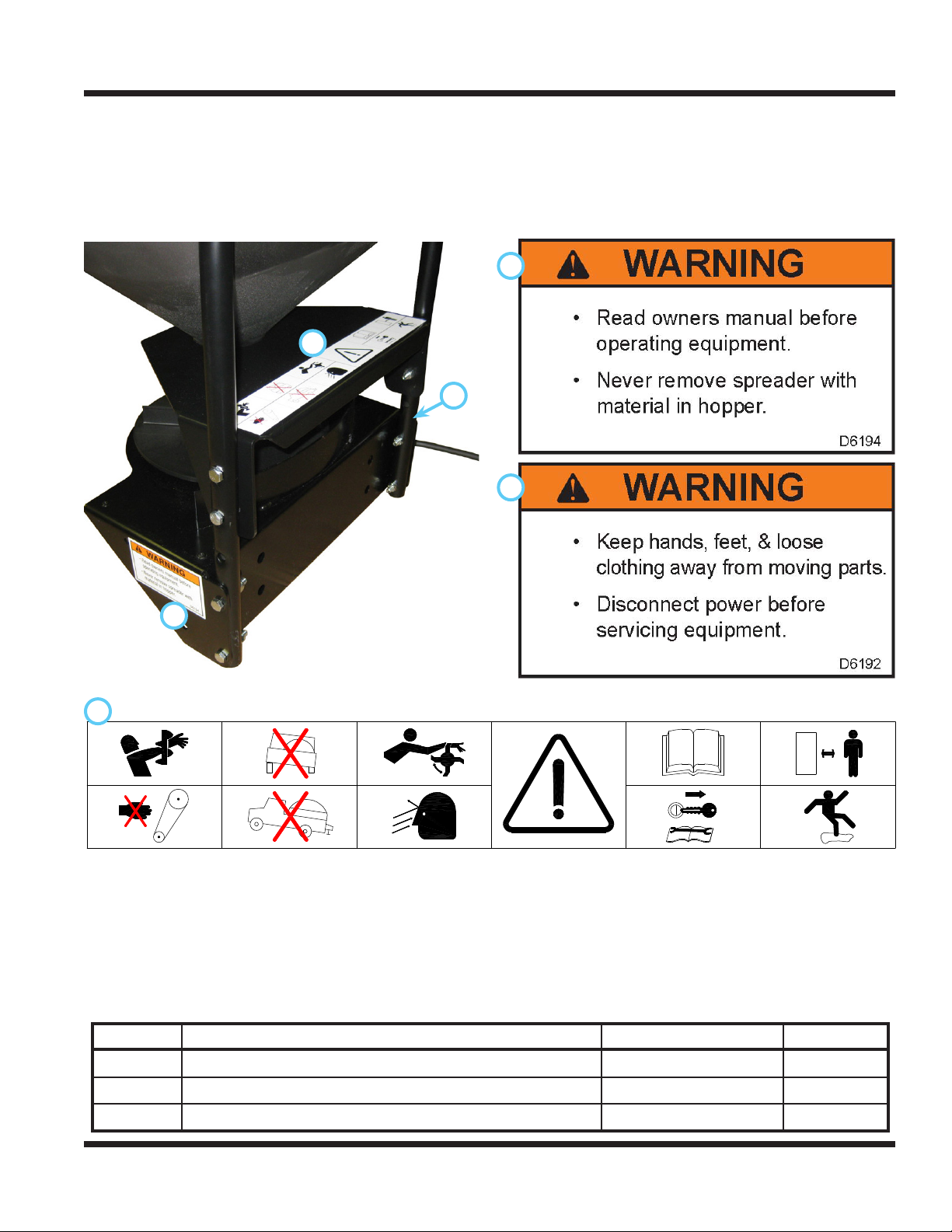
• Observe and follow all safety decals.
• All controls are to be operated from the operator’s seat only.
• Always wear a seat belt if the machine has a roll cage/bar installed.
• Ensure the attachment or accessory is locked or fastened securely to the power unit before operating.
• Ensure that all bystanders are clear of the power unit and attachment before operating. Stop machine if
someone enters your work area.
• Always be alert to what is happening around you, but do not lose focus on the task you are performing.
Always look in the direction the machine is moving.
• Look behind and down before backing up to be sure of a clear path.
• If you hit an object, stop and inspect the machine. Make all necessary repairs before operating machine again.
• Stop operation immediately at any sign of equipment failure. An unusual noise can be a warning of equipment
failure or a sign that maintenance is required. Make all necessary repairs before operating machine again.
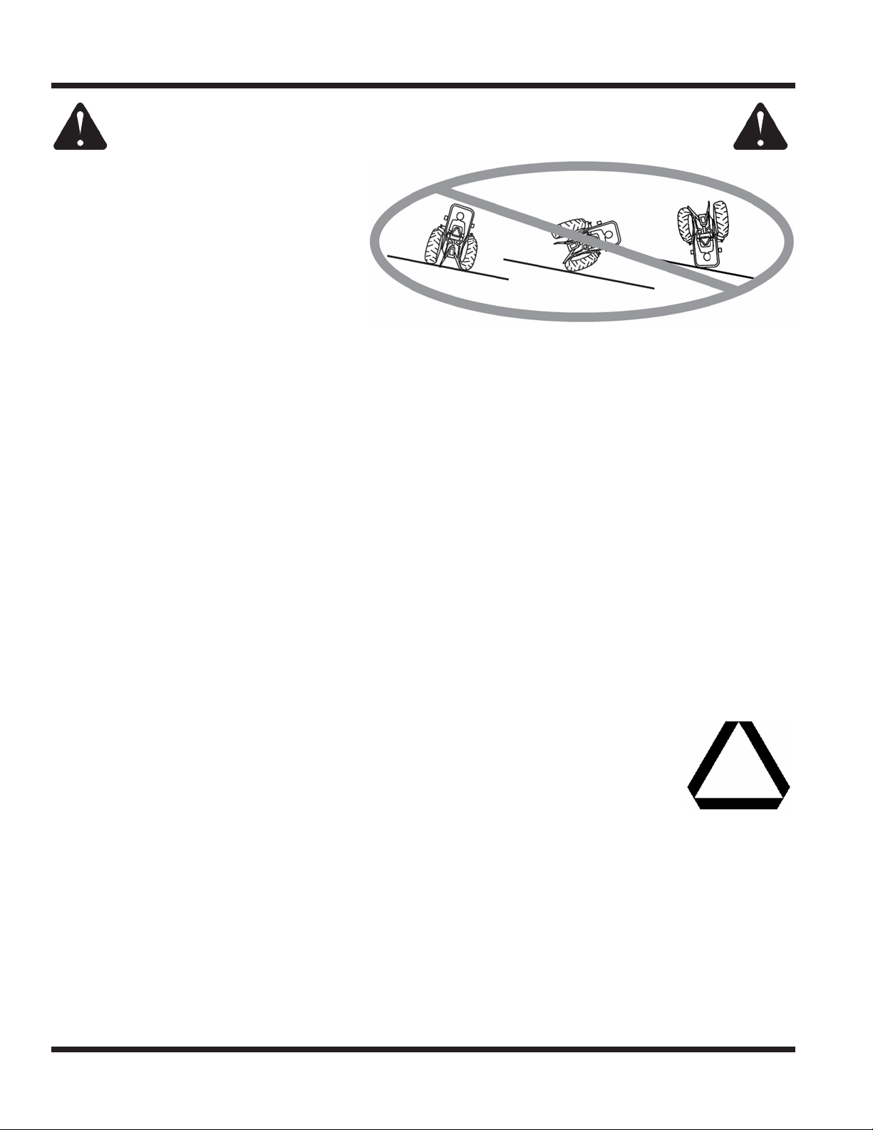
• If equipped with a high/low range feature, never shift between high and low range while on a slope.
Always move the machine to level ground and place the selector lever in park before shifting range.

SAFETY
General Safety Procedures
for Ventrac Power Units, Attachments, & Accessories
• Do not leave machine unattended while it is running.
• Always park the machine on level ground.
• Always shut o engine when connecting attachment drive belt to the power unit.
• Never leave the operator’s seat without lowering the attachment to the ground, setting the parking
brake, shutting o the engine, and removing the ignition key. Make sure all moving parts have come to
a complete stop before dismounting.
• Never leave equipment unattended without lowering the attachment to the ground, setting the parking
brake, shutting o the engine, and removing the ignition key.
• Only operate in well-lit conditions.
• Never direct the discharge of any attachment in the direction of people, buildings, animals, vehicles, or
other objects of value.
• Never discharge material against a wall or obstruction. Material may ricochet back towards the operator.
• Use extra caution when approaching blind corners, shrubs, trees, or other objects that may obscure vision.
• Do not run the engine in a building without adequate ventilation.
• Do not touch the engine or the muer while the engine is running or immediately after stopping the engine.
These areas may be hot enough to cause a burn.
• Do not change the engine governor settings or over-speed the engine. Operating engine at excessive speed
may increase the hazard of personal injury.
• To reduce the hazard of re, keep the battery compartment, engine, and muer areas free of grass, leaves,
and excessive grease.
• Clear working area of objects that might be hit or thrown from
machine.
• Keep people and pets out of mowing area.
• Know the work area well before operation. Do not operate where trac-
tion or stability is questionable.
• Reduce speed when you are operating over rough ground.
• Equipment can cause serious injury and/or death when improperly used.
Before operating, know and understand the operation and safety of the power
unit and the attachment being used.
• Do not operate machine if you are not in good physical and
mental health, if you will be distracted by personal devices, or
are under the inuence of any substance which might impair
decision, dexterity, or judgment.
• Children are attracted to machine activity. Be aware of children
and do not allow them in the working area. Turn o the machine
if a child enters the work area.
• Only allow the operator on the power unit. Keep riders o.
• Never allow riders on any attachment or accessory.

SAFETY
General Safety Procedures
for Ventrac Power Units, Attachments, & Accessories
• Slopes can cause loss-of-control and
tip-over accidents, which can result in
severe injury or death. Be familiar with the
emergency parking brake, along with the
power unit controls and their functions.
• If power unit is equipped with a fold down
roll bar, it must be locked in the upright
position when operating on any slope.
• Use low range when operating on slopes
greater than 15 degrees.
• Do not stop or start suddenly when operating on slopes.
• Never shift between high and low range while on a slope. Always move the power unit to level ground
and place the selector lever in park before shifting range.
• Variables such as wet surface and loose ground will reduce the degree of safety. Do not drive where
machine could lose traction or tip over.
• Keep alert for hidden hazards in the terrain.
• Stay away from drop-os, ditches, and embankments.
• Sharp turns should be avoided when operating on slopes.
• Pulling loads on hills decreases safety. It is the responsibility of the owner/operator to determine loads
that can safely be controlled on slopes.
• Transport machine with attachment lowered or close to the ground to improve stability.
• While operating on slopes, drive in an up and down direction when possible. If turning is necessary
while driving across slopes, reduce speed and turn slowly in the downhill direction.
• Assure a sucient supply of fuel for continuous operation. A minimum of one-half tank of fuel is recommended.
• Operate with safety lights when operating on or near roadways.
• Obey all state and local laws concerning operation on roadways.
• Slow down and be careful of trac when operating near or crossing roadways. Stop before crossing
roads or sidewalks. Use care when approaching areas or objects that may obscure vision.
• If there is doubt of safety conditions, discontinue machine operation until a time when
operation can be performed safely.
• When operating near or on roadways, have a Slow Moving Vehicle Emblem clearly
displayed.
• Use care when loading or unloading machine into a truck or trailer.
• The parking brake is not sucient to lock the machine during transport. Always secure the power unit
and/or attachment to the transporting vehicle.
• Shut o fuel supply to power unit during transport on truck or trailer.

SAFETY
General Safety Procedures
for Ventrac Power Units, Attachments, & Accessories
• Keep all safety decals legible. Remove all grease dirt, and debris from safety decals and instructional labels.
• If any decals are faded, illegible, or missing, contact your dealer promptly for replacements.
• When new components are installed, be sure that current safety decals are axed to the replacement
components.
• If any component requires replacement, use only original Ventrac replacement parts.
• Always disconnect the negative battery cable from the battery when working with electrical components.
• Keep all bolts, nuts, screws, and other fasteners properly tightened.
• Always lower the attachment to the ground, engage parking brake, shut o engine, and remove the
ignition key. Make sure all moving parts have come to a complete stop before cleaning, inspection,
adjusting or repairing.
• If the power unit, attachment, or accessory requires repairs or adjustments not instructed in the opera-
tor’s manual, the power unit, attachment, or accessory must be taken to an authorized Ventrac dealer
for service.
• Never perform maintenance on the power unit and/or attachment if someone is sitting in the operator’s seat.
• Always use protective glasses when handling the battery.
• Check all fuel lines for tightness and wear on a regular basis. Tighten or repair them as needed.
• To reduce the hazard of re, keep the battery compartment, engine, and muer areas free of grass,
leaves, and excessive grease.
• Do not touch the engine or the muer while the engine is running or immediately after stopping the
engine. These areas may be hot enough to cause a burn.
• Do not change the engine governor settings or over-speed the engine. Operating engine at excessive
speed may increase the hazard of personal injury.
• Springs may contain stored energy. Use caution when disengaging or removing springs.
• An obstruction or blockage in a drive system or moving/rotating parts may cause a buildup of stored
energy. When the obstruction or blockage is removed, the drive system or moving/rotating parts may
move suddenly. Do not attempt to remove an obstruction or blockage with your hands. Keep hands,
feet, and clothing away from all power-driven parts.
• Dispose of all uids in accordance with local laws.
• Do not refuel machine while smoking or at a location near ames or sparks.
• Always refuel the machine outdoors.
• Do not store machine or fuel container indoors where fumes or fuel can reach an
open ame, spark, or pilot light.
• Only store fuel in an approved container. Keep out of reach of children.
• Never remove gas cap or add fuel with the engine running. Allow engine to cool before refueling.
• Replace all fuel tank and container caps securely.
• Do not overll fuel tank.
• If fuel is spilled, do not attempt to start the engine. Move the power unit away from the fuel spill and
avoid creating any source of ignition until fuel vapors have dissipated.
• If the fuel tank must be drained, it should be drained outdoors into an approved container.
• Dispose of all uids in accordance with local laws.
• Check all fuel lines for tightness and wear on a regular basis. Tighten or repair them as needed.
• The fuel system is equipped with a shut-o valve. Shut o the fuel when transporting the machine to
and from the job, when parking the machine indoors, or when servicing the fuel system.

SAFETY
General Safety Procedures
for Ventrac Power Units, Attachments, & Accessories
• Make sure all hydraulic connections are tight and all hydraulic hoses and tubes are in good condition.
Repair any leaks and replace any damaged or deteriorated hoses or tubes before starting the machine.
• Hydraulic leaks can occur under high pressure. Hydraulic leaks require special care and attention.
• Use a piece of cardboard and a magnifying glass to locate sus-
pected hydraulic leaks.
•Keep body and hands away from pinhole leaks
or nozzles that eject high pressure hydraulic
uid. Hydraulic uid escaping under high pres-
sure can penetrate the skin causing serious
injury. If hydraulic uid is injected into skin, seek
immediate medical attention.
• Hydraulic system may contain stored energy. Before performing maintenance or repairs on the hydrau-
lic system, remove attachments, engage parking brake, disengage weight transfer system (if equipped),
shut o engine, and remove ignition key. To relieve pressure on the auxiliary hydraulic system, shut o
the power unit engine and move the secondary S.D.L.A. lever left and right before disconnecting the
auxiliary hydraulic quick couplers.
• Dispose of all uids in accordance with local laws.

SAFETY
• Spreader must be pinned and locked into position before operating power unit and spreader.
• Never exceed the recommendations in the weight capacity charts in the operation section, which speci-
es the material weight that can be used with dierent attachments. Exceeding the weight recommen-
dation for your front attachment may result in loss of steering or front wheel traction.
• Do not operate power unit with SS300 spreader on slopes greater than 10 degrees. Operation on
slopes greater than 10 degrees may result in loss of steering or front wheel traction.
• Never attempt to remove a spreader from the power unit while there is material in the spreader hopper.
• Always make sure personnel are clear of areas of danger when using equipment. Maintain 60’ distance
from all bystanders when operating the spreader.
• Never use with foreign debris in the spreader. The spreader is designed to handle only clean, free-ow-
ing material.
• Before working with the spreader, secure all loose tting clothing and unrestrained hair.
• Always wear safety glasses with side shields when servicing spreader.
• Read lead labels before attaching wire harness to power source or ground.
• Do not splice any other device into the wire harness.

1.
To prevent thread galling, hand tools and a thread
lubricant are recommended when tightening stain-
less steel fasteners. Do not use air or electric power
tools as this increases the potential of thread galling.
WARNING
Safety glasses must be worn during installation.
Install the hopper support tube (A) onto the trans-
mission mount weldment (B) using 4) 5/16” x 2”
bolts, 8) 5/16” washers, and 4) 5/16” locknuts. Do
not tighten.
2.
AA
BB
Install the auger onto the drive shaft. Align the
5/16” set screw (C) with the at on the drive
shaft and tighten securely.
CC
Press the plastic plug (D) into the top of the
auger shaft tube.
DD
3. Install the hopper support plate (E) onto the hop-
per support tube using 4) 5/16” x 2” bolts, 8) 5/16”
washers, and 4) 5/16” locknuts. Do not tighten.
4.
EE
Insert the hopper throat into the hopper support
plate and fasten the hopper to the hopper sup-
port tube using 4) 5/16” x 2” bolts, 5/16” x 1-1/2”
fender washers, and 5/16” locknuts. Torque to
135 in-lbs (15 Nm).
5. Adjust the hopper support tube until there is
clearance between the auger and the hopper
throat. Torque the bolts that fasten the hopper
support tube to the transmission mount weld-
ment to 135 in-lbs (15 Nm).
6. Adjust the hopper support plate to support the
hopper and prevent the hopper throat from
moving. Torque the bolts to 135 in-lbs (15 Nm).
7. Install the weather cover onto the hopper.
Spreader setup is nished. Complete the spreader
with the proper install kit for your power unit.

SPREADER SETUP & INSTALL KITS
1. Disconnect the negative battery cable from the
power unit’s battery.
2. Remove the nut and bolt from the positive and
negative battery cable clamps and replace them
with 5/16” x 1-1/2” bolts and nuts. Tighten the
positive clamp onto the positive battery terminal.
3. Install the fused positive wire onto the positive
cable clamp bolt and fasten with a 5/16” nut.
4. Install the negative cable onto the negative terminal
and tighten. Install the negative wire onto the nega-
tive cable clamp bolt and fasten with a 5/16” nut.
5. Using a side cut pliers, cut both battery terminal
covers at the locations shown and install onto
the battery terminals.
Cut HereCut Here
6. Install the spreader hitch onto the spreader using
4) 1/2” x 1-1/4” bolts and 4) 1/2” at washers. Use
Loctite 242 or equivalent thread locker on bolts.
Torque to 45 ft-lbs (61 Nm).
7. Fasten the spreader’s power cord to the hitch
frame at two places using zip ties.
Document Number Kit Number / Part Number Model Serial Number Range
09.700131 70.8112 SS300 All Units
09.700131 70.8113 SS575 All Units
Tools Required: 3/8” wrench 7/16” wrench* 1/2” wrench 9/16” socket* 3/4” socket
impact driver 7/32” drill bit* drill* phillips screwdriver side cut pliers
Before making repairs or adjustments set the parking
brake, turn o engine, and remove ignition key.
Always disconnect the negative battery cable from the
battery when working with electrical components. Always
work in a manner that does not put safety at risk!
Safety glasses must be worn during installation.
Ear (hearing) protection must be worn when
using air or power tools.
Installation Time (estimated) 1 hour
Installation Notes: Right and left hand orienta-
tion referred to in these instructions is determined
as if sitting on the tractor seat, facing forwards.
*Not necessary for all setup congurations.

SPREADER SETUP & INSTALL KITS
8. Insert the spreader hitch into the power unit’s
receiver hitch tube and fasten with a 5/8” x 3”
clevis pin and a 1/8” x 2-1/2” hairpin.
CAUTION
If the power unit is equipped with a 3 point hitch,
adjust the lift arm links to position the lift arms
in the outermost position to prevent damage to
spreader if 3 point lift arms are raised accidentally.
1. Fasten the controller bracket (A) to the control
box mount bracket (B) using 2) #10-32 x 1/2”
machine screws and #10-32 ange nuts.
2.
AA
BB
Place the nylon washers on the inside of the
controller bracket and install onto the controller
using the 1/4” bolts and at washers. Tighten the
bolts until the controller pivots with resistance.
(If power unit is equipped with cab, skip to next section)
1. Insert the tabs of the frame clamp bracket into
the slots of the frame mount bracket and fasten
with 3/8”x 2” carriage bolts and knobs.
2. Place the frame mount bracket against the inside
of the right leg of the roll bar. Position the bot-
tom edge of the frame mount bracket 24 -25
inches from the bottom of the roll bar and install
2) u-bolts and 4) locking ange nuts. Torque the
ange nuts to 31 ft-lbs (42 Nm).
3. Insert the arm of the control box mount into the
frame clamp bracket.

SPREADER SETUP & INSTALL KITS
4. Install the spreader control box bracket onto
the control box mount using 2) #10-32 x 1/2”
machine screws and #10-32 ange nuts.
5. Fully extend the control box mount arm and tighten
the knobs to clamp the control box mount in place.
6. Connect the battery/
controller wire harness
to the positive and
negative wires con-
nected to the power
unit battery. Connect
the harness to the
battery lead on the
spreader controller.
7. Connect the motor/controller wire harness to the
motor lead on the spreader controller. Connect the
harness to the power cord on the spreader. NOTE:
if the power unit is equipped with a 3 point hitch,
route the harness down between the power unit
seat box and the pivot shaft on the 3 point hitch
before connecting to the spreader’s power cord.
8. Use Velcro ties to fasten both wire harnesses
to the arm of the control box mount just behind
the controller and also to fasten the harnesses
together, but not to the control box arm, about
halfway back to the roll bar.
9. Leave a small amount of slack in the wire harnesses
and use Velcro ties to fasten the harnesses to the
roll bar just below the frame mount bracket and right
above the power unit fender as shown above.
10. Coil the extra wire of the motor/controller har-
ness at the corner of the right fender and use a
Velcro tie to fasten both harnesses to the power
unit seat box. Fasten the coils of the motor/con-
troller harness together using a Velcro tie.
11. Coil the extra wire of the battery/controller har-
ness at the corner of the left fender and use a
Velcro tie to fasten to the power unit seat box.
12.
Fuse HolderFuse Holder
Install the circuit breaker into the fuse holder of
the positive wire as shown above.
Installation is complete.
1. Remove the tunnel cover from the lower rear
frame of the power unit.
2. On KW350 cabs with serial numbers 1001-1060,
a mounting hole must be drilled in the dash tray
of the bottom windshield mount. Measure
2-11/16” in from the inside of the rear lip and
5-1/2” in from the inside of the right lip.
5-1/2”5-1/2”
2-11/16”2-11/16”

SPREADER SETUP & INSTALL KITS
Drill the mounting hole using a 7/32” drill bit,
remove any metal shavings, and use touch up
paint on exposed metal.
3. Install the spreader control box bracket onto the
bottom of the tray using 2) #10-32 x 1/2” machine
screws and #10-32 ange nuts.
4. Connect the battery/controller wire harness to
the battery lead on the spreader controller and
connect the motor/controller wire harness to the
motor lead on the spreader controller.
5. Route the wire harnesses
down along the cab post and
fasten to the gate cable mount
bracket using a Velcro tie.
6. Route the wire harnesses
under the foot plate of the
power unit. Fasten underneath
the foot plate and to the side
of the lower rear frame tunnel
using 2) cushioned clamps
and 1/4” x 3/4” ange bolts
and ange nuts.
7. Route the wire harnesses under the hydraulic
lter, up over the axle housing, and out the back
of the power unit.
8. Insert the battery/
controller wire har-
ness between the
power unit seat box
and canvas window
of the cab and con-
nect to the positive
and negative wires
connected to the power unit battery and fasten to
the cab wire harness using a Velcro tie.
9. Connect the harness to the power cord on the
spreader. NOTE: if the power unit is equipped
with a 3 point hitch, route the harness down
between the power unit seat box and the pivot
shaft on the 3 point hitch before connecting to
the spreader’s power cord.
10. Coil the extra wire from the battery/controller and
motor/controller wire harnesses at the back of the
power unit and fasten to the hitch frame upper
anchor bracket using a Velcro tie.

SPREADER SETUP & INSTALL KITS
11.
Fuse HolderFuse Holder
Install the circuit breaker into the fuse holder of
the positive wire as shown above.
12. Reinstall the power unit’s tunnel cover.
Installation is complete.

SPREADER SETUP & INSTALL KITS
1. Open the engine hood and disconnect the nega-
tive battery cable from the battery.
2. Remove the tunnel access cover and the steer-
ing column cover from the power unit.
3. Route the controller ends of the battery/controller
wire harness and the motor/controller wire har-
ness under the power unit’s seat plate, through
the tunnel area, and up through the steering
column.
4. Place the steering column cover back onto the
steering column using care not to pinch the wire
harnesses. Do not fasten.
5. Place a 1/4” at washer onto the
1/4” x 3/4” ange bolt and insert the
ange bolt through the small hole
in the control box mount bracket.
Place another 1/4” at washer onto
the ange bolt and install in the right
upper hole of the steering column
cover with the ange of the control
box mount bracket hooked over the top edge of
the steering column cover. Do not tighten.
6. Place 2) disc springs onto a 3/8” x 1” bolt. Orient
the disc springs so the peak of the coned disc is
against the bolt head. Place a 3/8” at washer
onto the bolt and insert through the hole on the
control box mount bracket as shown below.
Place another 3/8” at washer onto the bolt,
install the control box bracket onto the bolt, and
fasten with a 3/8” locking ange nut.
Tighten until the control box bracket is held in
place, but can still be adjusted, if necessary.
Before making repairs or adjustments set the parking
brake, turn o engine, and remove ignition key.
Always disconnect the negative battery cable from the
battery when working with electrical components. Always
work in a manner that does not put safety at risk!
Safety glasses must be worn during installation.
Ear (hearing) protection must be worn when
using air or power tools.
Installation Time (estimated) 1 hour
Installation Notes: Right and left hand orienta-
tion referred to in these instructions is determined
as if sitting on the tractor seat, facing forwards.
Document Number Kit Number / Part Number Model Serial Number Range
09.700130 70.8125 SS300 All Units
Tools Required: 3/8” socket 1/2” wrench* 1/2” socket* 9/16” wrench 9/16” socket
15/16” wrench 15/16” socket 12mm wrench* impact driver phillips screwdriver
*Not necessary for all setup congurations.
Table of contents
Other Venture Products Spreader manuals
Popular Spreader manuals by other brands

Western
Western LOW-PRO 300 Owner's manual and installation instructions

Cub Cadet
Cub Cadet 19A30028100 installation manual

Butts of Bawtry
Butts of Bawtry SP80WB instruction manual

Simplex
Simplex S2000A Operating instructions manual

Durapac
Durapac DHS-5 instruction manual

PermaGreen Supreme
PermaGreen Supreme CHEMmando Cavalry 60 A1B Operator's manual

Earth Way
Earth Way EV-N-Spred C22HD Assembly and operating instructions

Tube-Line
Tube-Line NITRO 275RS Operator's manual

BE Ag & Industrial
BE Ag & Industrial BE-PFS G Series Operations & parts manual

The Handy
The Handy THS125 Operator's manual and parts list

AGREX
AGREX XT 300 user guide

Buyers
Buyers Salt Dogg SHPE1500 installation instructions